Author Archives: Amelia.Liu

Punch-Down Block and Patch Panel

Share

The cable runs in a structured cabling environment terminate in a punch-down block, which is usually a 66-block or a 110-block, or BIX- or Krone-style blocks, “Cabling System Connections and Termination.” The 110-block is most commonly used for voice and data cabling termination, although you will find many installations that use a 110-block for termination voice systems and patch panel for terminating data systems. Punch-down block termination provides a cross-connect from one cable set to another, allowing for easier moves, adds, and changes (MACs) as the need arises.

What Is A Punch-Down Block?

A punch-down block is mounted to a backboard, which is usually made of plywood and secured to the wall of a TC. If you install cabling on more than the floor, each floor must have a separate punch-down block with terminations for the cable drops from the higher floors. Backbone cables should be installed with 10-foot service coils at the termination points, which are commonly located on the backboard in the closet. Figure 1 illustrates a typical TC.

Install patch cables from the punch-down block to a patch panel. The purpose of the patch panel is to connect the backbone system to networking equipment such as a hub or router. End-user equipment, which includes workstations, network printers and scanners, and other shared electronic equipment, generally connect to a hub (also called a concentrator) or router via RJ-45 cable jacks or outlets.

There are pros and cons to using cross-connect blocks. They offer higher densities and require less space than patch panels, and also are less expensive. On the other hand, they are the least friendly for making moves, adds, and changes to the configuration. Skill is involved in removing and rea-ranging cables. When using patch panels, almost anyone can rearrange the system. In both situations security, ease of attachment, expense, and physical space are all considerations.

What Is Fiber Optic Patch Panel?

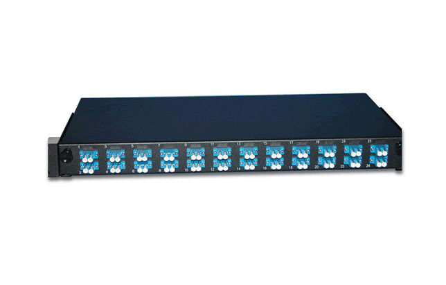
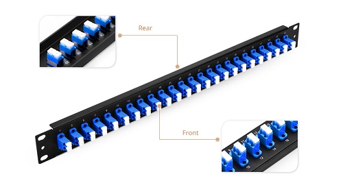
Fiber optic patch panel is commonly used in fiber optic management unit. When you install and manage the fiber optic links, you may encounter hundreds or even thousands of fiber optic cables and cable connections, fiber optic management products are used to offer space and protection for the fiber cables and cable links, and they make it easier for the cable management and troubleshoot work. Our fiber optic patch panels are all sliding type, they are compatible to use with equipment and cable assembly products from other companies. Now you can see the two products from our store. They are SC fiber patch panel, 24 Port Fiber Patch Panel.

12 port  OS1/2 9μm Duplex Plastic SC Fiber Patch Panel

Features of FS001 SERIES MOLDED

● Compatible with Leviton fiber adapter panels
● Adapter panels offered in LC, SC, ST, and blank styles, fit for all Opt-X rack-mount and wall-mount enclosures and VertiGO® panels
● Equipped with plastic dust caps to make connecting panels tool-free and efficient
● Integrated couplers eliminate “rattle” and loose fit
● Captive push-lock pins allow for quick tool-less installationCaptive push-lock pins allow for quick tool-less installation
● Exceeds optical performance standards and meets all other applicable standards

12 pack LC Duplex 24 Port Fiber Patch Panel Blue

24 port Patch Panel

● Compatible with BlackBox Fiber Adapter Panel
● Adapter panels snap easily into all standard fiber enclosures, cabinets, and patch panels, including all Black Box® models.
● High-density panels with ST or LC connectors are available.
● The easy way to patch fiber cables to termination enclosures

We supply many fiber optic patch panels. They are with types to fit from 12 fibers to 72 fiber management demand. These fiber optic patch panels are with optional various kinds of fiber optic adapters and fiber optic pigtails, types including SC, LC, ST, FC, MU, E2000, etc.  We have a number of different customizable options available to fit whatever application you require. With products compatible with trusted brands including Black Box, Wirewerks, Mr-technologies, Corning, Leviton, Panduit Opticom adapter panel and more.

Fiber Optic Enclosures In Cabling Systems

Share

Overview of Fiber Optic Enclosures

Just like copper-based cabling systems, fiber-optic cabling systems have a few specialized components, including fiber optic enclosures and connectors.

Because laser light is dangerous, the ends of every fiber-optic cable must be encased in some kind of fiber optic enclosure. The fiber optic enclosure not only protects humans from laser light but also protects the fiber from damage. Wall plates and patch panels are the two main types of fiber optic enclosures. We’ll discuss patch panels here.

When most people think about a fiber optic enclosure, a fiber patch panel comes to mind. It allows connections between different devices to be made and broken at the will of the network administrator. Basically, a bunch of fiber-optic cables will terminate in a patch panel. Then, short fiber-optic patch or interconnect cables are used to make connections between the various cables. There are dust caps on all the fiber-optic ports, which can prevent dust from getting into the connector and interfering with a proper connection.

Types of Fiber Optic Enclosures

Patch panels come in many shapes and sizes. Some are mounted on a wall and are known as surface-mount patch panels. Others are mounted in a rack and are called rack mount patch panels. Each type has its own benefits. Surface mount panels are cheaper and easier to work with, but they can’t hold as many cables and ports. Surface-mount patch panels make good choices for smaller (fewer than 50 drops) cabling installation. Rack-mount panels are more flexible, but they are more expensive. Rack mount patch panels make better choices for larger installations. Patch panels are the main products used in LAN installations today because they are extremely cost-effective and allow great flexibility when connecting workstations.

In addition to the standard fiber patch panels, a fiber-optic installation may have one or more fiber distribution panels, which are very similar to patch panels in that many cables interconnect them. However, in a distribution panel, the connections are more permanent. Distributions panels usually have a lock and key to prevent end users from making unauthorized changes. Generally speaking, a patch panel is found wherever fiber optic equipment hubs, switches, and routers are found. Distribution panels are found wherever multifiber cables are split out into individual cables. Here is the example of 24 port patch panel.

24 port patch panel

Our wall mounted fiber optic enclosures accommodate up to 8 modular panels and is equipped with routing guides to limit bend radius and enhance strain-relief control. The 16-gauge steel with corrosion-resistant black powder finish coat housing provides excellent protection for the inside fibers. Wall-mount available unloaded, as well as having the capability to become a full-splice enclosure with mechanical terminations. A large variety of connector adapters are offered to meet your specific requirements. Such as SC, FC, ST, LC, etc, we can also pre-install various kinds of fiber optic pigtails inside the patch panel. We offer a series of changeable inside panels to fit for different kinds of the adaptor interface, and fit for both round and ribbon fiber optic cables.

Some Knoweledge About Erbium-droped Fiber Amplifer

Share

The eribum-doped fiber amplifier (EDFA) was first reported in 1987, and, in the short period since then, its applications have transformed the optical communications industry. Before the advent of optical amplifers, optical transmission systems typically consisted of a digital transmitter and a receivere separated by spans of transmission optical fiber intersersed with optoelectronic regenerators. The optoelectronic regenerators corrected attenuation, dispersion, and other transmission degradations of the optical signal by detecting the attenuated and distorted data pulses, electronically reconstituting them, and then optically transmitting the regenerated data into the next transmission span.

The EDFA is an optical amplifer that faithfully amplifies lightwave signals purely in the optical domain. EDFAs have several potential functions in optical fiber transmission systems. They can be used as power amplifiers to boost transmitter power, as repeaters or in-line amplifiers to increase system reach, or as preamplifiers to enhance receiver sensitivity. The most far-reaching impact of EDFAs has resulted from their use as repeaters in place of conventional optoelectronic regenerators to compensate for transmission loss and extend the span between digital terminals. Used as a repeater, the optical amplifier offers the possibility of transforming the optical transmission line into a transparent optical pipeline that will support signals independent of their modulation format or their channel data rate. Additionally, optical amplifiers support the use of wavelenth division multiplexing (WDM), whereby signals of different wavelengths are combined and transmitted together on the same transmission fiber.

In fiber optic systems amplification of the signal is necessary because no fiber material is absolutely transparent. This causes the infrared light (usually around 1530nm) carried by a fiber to be attenuated as it travels through the material. Because of this attenuation, repeaters must be used in spans of optical fiber longer than approximately 100 kilometers.

The operating wavelength range of a standard EDFA spans over the entire so-called “C band” (1530 to 1560 nm) and therefore allows amplification of a variety of wavelength channels that are used in wave-length division multiplexing (WDM)applications. This is a major advantage over methods in which the optical signal is converted into an electrical signal, amplified and converted back to light. Due to the last step, such O/E-E/O regenerators require the demultiplexing and multiplexing of each single WDM channel at each regenerator site and an O/E-E/O pair for each channel.

EDFA Configurations

The configuration of a co-propagating EDFA is shown in Figure 5. The optical pump is combined with the optical signal into the erbium-doped fiber with a wavelength division multiplexer. A second multiplexer removes residual pump light from the fiber. An in-line optical filter provides additional insurance that pump light does not reach the output of the optical amplifiers. An optical isolator is used to prevent reflected light from other portions of the optical system from entering the amplifier.

fiber optic amplifer

Figure 5. An EDFA for which the optical signal and optical pump are co-propagating.

An EDFA with a counter propagating pump is pictured in Figure 6. The co-propagating geometry produces an amplifier with less noise and less output power. The counter propagating geometry produces a noisier amplifier with high output power. A compromise can be made by combining the co- and counter-propagating geometries in a bi-directional configuration.

EDFA Amplifer

The propagation and amplification properties of an erbium-doped fiber at 1550 nm are obtained. A simple EDFA is constructed, and its performance is tested. A small signal with wavelength of 1530 nm can be amplified with amplification up to 14 dB/m and SNR of 18.8, if a pumping laser of wavelength 980 nm and driving current 400 mA is used. A higher amplification is expected if a more intense pumping laser is supplied. The erbium doped fiber amplifier proves efficient and concise in amplifying signals around 1550 nm.

FBG Sensor Multiplexing Techniques On WDM System

Share

Fiber Bragg Grating (FBG) is a simple and low-cost filter built into the core of a wavelength-specific fiber cable. FBGs are used as inline optical filters to block certain wavelengths, or as wavelength-specific reflectors.

In many applications a large number of sensors need to be used to achieve a distributed measurement of the parameters. In particular, using sensors in smart structures is of interest where sensor arrays are bonded or embedded into the materials to monitor the health of the structure. FBG sensors have a distinct advantage over other sensors because they are simple, intrinsic sensing elements that can be written into a fiber, and many sensors can be interrogated through a single fiber.

The most straightforward multiplexing technique for FBG sensors is wavelength division multiplexing (WDM), utilizing the wavelength-encording feature of an FBG-based sensor. The WDM technique is based on spectral splicing of an available source specturm. Each FBG sensor can be encoded with a unique wavelength along a single fiber. Since we are operating in the wavelength domain, the physical spacing between FBG sensors can be as short as desired to give accurate distributed information of measurands.

A parallel topology is used to allow simultaneous interrogation of all the sensors in WDM, as shown in Figure 4.15. A1 x N fiber optic splitter is used to divide the optical reflection into N channels, In each channel a matched fiber grating detects the wavelength shift from a specific FBG sensor.

Fiber splitter

In the parallel scheme each filter receives less than 1/2N of optical power as a result of using 1 x N fiber splitter and fiber coupler. More FBG sensors lead to a larger power penalty. An improved scheme using a serial matched FBG array is reported by Brady et al, as shown in Figure 4.15(b). This scheme is claimed to allow the optical power to be used more efficently than in the parallel topology. As can be seen, however, a large power penalty still exists through the use of the reflection of matched fiber gratings. A revised verison of the serial scheme is proposed, in which the transmisson of the matched FBG is used to monitor the wavelength shift from the corresponding sensing FBG. This reduces the power penalty of 6 dB.

Some Fiber Optic Cable Type Introduction

Share

Fiber optic “cable” refers to the complete assembly of fibers, other internal parts like buffer tubes, ripcords, stiffeners, strength members all included inside an outer protective covering called the jacket. Fiber optic cables come in lots of different types, depending on the number of fibers and how and where it will be installed. It is important to choose cable carefully as the choice will affect how easy the cable is to install, splice or terminate and what it will cost. Next, we will introduce 5 types of fiber optic cable in communication.

Distribution Cable

When it is necessary to run a large number of fibers through a building, distribution cable is often used. Distribution cable consists of multiple tight-buffered fibers bundled in a jacket with a strength member. Typically, these cables may also form subcables within a larger distribution cable.

Distribution Cable

Distribution cables usually end up at patch panels or communication closets, where they ar hooked into devices that communicate with separate offices or locations. These fibers are not meant to run outside of office walls or be handled beyond the intial installation, because they do not have individual jackets.

Distribution cables often carry up to 144 individual fibers, many of which may not be used immediately bu should be considered for future expansion.

Breakout Cable

Breakout cables are used to carry fibers that will have individual connectors attached, rather than being connected to a patch panel.

Breakout cables consist of two or more simplex cables bundled around a central strength member and covered with an outer jackets. Like distribution cable, breakout cables may be run through a bulding’s walls, but the individual simplex cords can then be broken out and handled individually.

As is the case with distribution cable, breakout cables may end up in communication closets, but in the case of breakout cables, users can manmually change connections. Breakout cables may also be used to connect directly to equipment.

Armored cable

Armored cable, addresses the special needs of outdoor cable that will be exposed to potential damage from equipment, rodents, and other especially harsh attacks.

Armored fiber cable consists of a cable surrounded by a steel or aluminum jacket which is then covered with a polyethylene jacket to protect it from moisture and abrasion. It may be run aerially, installed in ducts, or placed in underground enclosures with special protection from dirt and clay intrusion.

Messenger Cable

When a fiber optic cable must be suspended between two poles or other structures, the strenth members alone are not enough to support the weight of the cable. Installers must use a messenger cable, which incorporates a steel or dielectric line known as a messenger to take the weight of the cable. The cable carrying the fiber is attached to the messenger by a thin web an hangs below it.

Also called Figure 8 Fiber Optic cable for the appearance of its cross section, messenger cable greatly speeds up installation of aerial cable by eliminating the need to lash a cable to a pre-run messenger line.

In applications that will run near power lines, the dielectric messenger is ofen used to minimize the risk of energizing the cable through induced current, which is created when the electrical field from a high voltage alternating current line expands and contracts over a nearby conductor. If a conductive cable is close enough to the alternating current, the induced current may be srong enough to injure someone working near the cable.

It’s a good practice, in fact, to use dielectric strength members wherever tension considerations permit, as this will help avoid any potential conductivity problems in the cable.

Hybrid cable

Hybrid cable, as applied to fiber optics, combines multimode and single-mode fibers in one cable. Hybrid cable should not be confused with composite cable, although the terms have been used interchangeably in the past.

FiberStore is one of the industry’s fastest growing fiber optic cable manufacturer, specializing in providing quality, cost-effective retailing, wholesale and OEM fiber optic products. For more information on bulk fiber optic cable and customization service, please email to sales@fs.com or visit fs.com.

Three Common Types Of Fiber Optic Cable

Share

There are three common types of fiber optic cables , as listed below. The suitability of each type for a particular application depends on the fiber optic cable’s characteristics.

The single mode fiber optic cable, sometimes called a single-mode fiber cable, is shown in Figure 1.5(a). The single and multimode step-index fiber cables are the simpplest types of fiber optic cables. Single-mode fiber cables have extremely small core diameters, ranging from 5 to 9.5 um. The core is surrounded by a standard cladding diameter of 125 um. The jacket is applied on the cladding to provide mechanical protection, as shown in Figure 1.3. Jackets are made of one type of polymer in different colours for colour-coding purposes. Single-mode fibers have the potential to carry signals for long distances with low loss, and are mainly used in communication systems. The number of modes that propagate in a single-mode fiber depends on the wavelength of light carried. The number of modes will be given in Equation (1.9). A wavelength of 980nm results in multimode operation. As the wavelength is increased, the fiber carries fewer and fewer modes until only one mode remains. Single-mode operation begins when the wavelength approaches the core diameter. At 1310 nm, for example, the fiber cable permits only one mode. It then operates as a single-mode fiber cable.

singlemode types of fiber optic cables

The multimode types of fiber optic cables, sometimes called a multimode fiber cable. Multimode fiber cables have bigger diameters that their single-mode counerparts, with core diameters ranging from 100 to 970 um. They are available as glass fibers (a glass core and glass cladding), plastic-clas silica (a glass core and plastic cladding), and plastic fibers (a plastic core and cladding). They are also the widest ranging, although not the most efficient in long distances, and they experience higher losses than the single-mode fiber cables. Multimode fiber cables have the potential to carry signals for moderate and long distance with low loss (when optical amplifiers are used to boost the signals to the required power). Plastic fiber optic cable is available in Fiberstore,  it is an optical fiber made out of plastic rather than traditional glass. It offers additional durability for uses in data communications, as well as decoration, illumination and industrial application. FiberStore provides both simplex and duplex plastic optical fibers.

Since light rays bounded through a fiber cable reflect at different angles for different ray pathc, the path lengths of different modes will aslo be different. Thus, different rays take a shorter or longer time to travel the lenth of the fiber cable. The ray that goes straight down the centre of the core without reflecting arrives at the other end faster. Other rays take slightly longer and thus arrive later. Accoringly, light rays entering a fiber at the same time will exit at the other end at different times. In time, the light will spread out because of the different modes. This is called modal dispersion. Dispersion describes the spreading of light rays by various mechanisms. Modal dispersion is that type of dispersion that results from the varying modal patch lengths in the fiber cable.

Multimode graded-index fiber are sometimes called graded-index fiber cables (GRIN). Graded-index and multimode fiber cables have similar diameters. Common graded-index fibers have core diameters of 50,62.5, or 85 um, with a cladding diameter of 125 um. The core consist of numerous concentric layers of glass, somewhat like the annular rings of a tree or a piece of onion. Each successive layer expanding outward from the central axis of the core until the inner diameter of the cladding has a lower index of refrection. Light travels faster in an optical material that has a lower index of refraction. Thus, the further the light is from the centre axis, the greater its speed. These types of fiber optic cable are popular in applications that require a wide range of wavelenths, in particular telecommunication, scanning, imaging, and data processing stystems. In particular telecommunication,  Multimode OM4 fiber optic cable is used in any data center looking for high speeds of 10G or even 40G or 100G. OM4 multimode fiber are ideal for using in many applications such as Local Area Networks (LAN) backbones, Storage Area Networks (SAN), Data Centers and Central Offices.

multimode fiber

You may have got some basics of types of fiber optic cables. Fiberstore provides a wide range of types of fiber optic cable with detailed specifications displayed for your convenient selecting. Per foot price of each fiber cable is flexible depending on the quantities of your order, making your cost of large order unexpected lower. Customers can also have the flexibility to custom the cable plant to best fit their needs.

Related Article: The Advantages and Disadvantages of Optical Fiber

Related Article: What Kind of Fiber Patch Cord Should I Choose?

Two Basic Types Of Fiber Optic Cable Construction

Share

Based on 900um tight buffered fiber and 250um coated fiber there are two basic types of fiber optic cable constructions – Tight Buffered Cable and Loose Tube Cable.

Loose Buffer

A loose buffer’s inner diameter is much larger than a fiber’s outer diameter. Two major advantages from this design are perfect fiber isolation from mechanical forces (within given range) and protection from moisture. The first advantage is due to mechanical dead zone. A force imposed on a buffer does not affect the fiber until this force becomes large enough to straighten the fiber inside the buffer. A loose buffer can be easily filled with a water-blocking gel, which provides its second advantage. In addition, a loose buffer can accommodate several fibers, thus reducing the cost of the cable. On the other hand, this type of cable cannot be installed vertiacally and its end preparation for connectorization (splicing and termination) is labour-intensive. Conseuqently, the loose buffer type of cable is used mostly in outdoor installations because it provides stable and reliable transmission over a wide range of temperatures, mechanical stress, and other environment conditions.

Loose tube structure isolates the fibers from the cable structure. This is a big advantage in handling thermal and other stresses encountered outdoors, which is why most loose tube fiber optic cables are built for outdoor applications. In outside application, ADSS Cable is the special loose tube cable.

Loose-tube cables typically are used for outside-plant installation in aerial, duct and direct-buried applications.

loose tube cable

Structure of a Loose Tube Cable

Elements in a loose tube fiber optic cable:

1. Multiple 250um coated bare fibers (in loose tube)
2. One or more loose tubes holding 250um bare fibers. Loose tubes strand around the central strength member.
3. Moisture blocking gel in each loose tube for water blocking and protection of 250um fibers
4. Central strength member (in the center of the cable and is stranded around by loose tubes)
5. Aramid Yarn as strength member
6. Ripcord (for easy removal of outer jacket)
7. Outer jacket (Polyethylene is most common for outdoor cables because of its moisture resistant, abrasion resistant and stable over wide temperature range characteristics. )

Tight Buffer

A tight buffer’s inner diameter is equal to the fiber’s coating diameter, as illustrated in Figure 2.33. Its primary advantage is ists ability to keep the cable operational despite a break in the fiber. Since a buffer holds a fiber firmly, a small separation of the fiber ends won’t interrupt the service completely, althought it will definitely degrade signal quality. That is why the military was the first customer and still is the largest for this type of fiber cable. A tight buffer is rugeed, allowing a smaller bend radius. Since each buffer contains only one fiber and there is no gel to be removed, it is easy to prepare this cable for connectorization. Cables having a tight buffer can be installed vertically. In general, tight buffer cables are more sensitive to temperature, mechanical and water impacts than the loose buffer cables; hence, they are recommended mostly for indoor applications. On the other hand, tight buffer cables designed for special applications (such as military and undersea are the strongest cable available.

Tight buffered cables are mostly built for indoor applications, although some tight buffered cables have been built for outdoor applications too. Here we recommend you a good site to buy fiber optic cable, fiberstore is a fantastic selection of fiber optic cable, including simplex,duplex,tight buffered,breakout, breakout,  plastic fiber optic  cable etc. More information want to know, search fiberstore on Google.

Structure of a Tight Buffered Cable

outdoor cable

Elements in a tight buffered fiber optic cable

1. Multiple 900um tight buffered fibers (stranded around the central strength member)
2. Central strength member (in the center of the cable)
3. Aramid Yarn (trade name Kevlar, Kevlar was developed by Dupont) (wrapped around the fibers, for physical protection and cable pulling)
4. Ripcord (for easy removal of outer jacket)
5. Outer jacket (also called sheath, PVC is most common for indoor cables because of its flexible, fire-retardant and easy extrusion characteristics. )

Fiberstore specializes in fiber optic cable assemblies and fiber optic network devices manufacturing, we are known as the fiber optic cable manufacturer for the excellent products quality, competitive prices, fast delivery and good service. We not only offer bulk fiber optic cable assemblies to some world leading companies in this industry, but we also cooperate with many other companies from all over the world and support these partners to win in the market. We are professional China fiber optic company.

Loose-tube vs Tight-buffered Cable

Share

Choosing the right fiber-optic cable has become more challenging than ever. The advent of new cable designs, many suppliers, changes in fiber specifications, and the many claims of cable performance can confuse even the most seasoned designers.The selection of the basic cable design is most dependent on the application and installation environment. The main objective in the cable design is to protect the fiber from stress and other environmental forces during installation and over the life of the product. From a technical standpoint, more than one type of cable may fit the bill for many applications. In that case, other factors such as ease of use, size, and cost will be added to the evaluation and selection process.

Let`s begin outside. The outdoor environment subjects a cable to the most extreme range of environmental condi- tions. These conditions include a wide operation-temperature range, thermal shock, wind loading, ice loading, moisture, and lightning. Therefore, protecting and preserving the optical properties of the fiber is a design priority.

The most proven fiber-optic cable technology for long-term reliability outdoors is the loose-tube, gel-filled design. This type of cable protects the fiber from stresses caused by the environment, namely moisture and temperature. Loose-tube cables, whether flooded under the jacket or water-blocked with dry, swellable materials, protect the fibers from moisture and the long-term degradation moisture can cause. As we all know, Fiberstore is the largest bulk fiber optic cable supplier, we provides a wide range of quality optical fiber cables with detailed specifications displayed for your convenient selecting.

The gel within the loose-tube construction stops the penetration of water and keeps it away from the fiber. In cold temperatures, the protection keeps water from freezing near the fiber–eliminating possible stress fractures. Since the fibers are able to move within the tube, the expansion or contraction that temperature fluctuations can produce in other materials does not transmit stress to the fibers.

Overall, loose-tube cables offer the best protection in an outdoor environment, especially in the less-sheltered applications involving aerial or direct-buried installations. The loose-tube design isolates the fibers from outside environmental and mechanical stresses. The optical performance is virtually unchanged as the cable is exposed to the elements. Telcordia Technologies, BICSI, RUS (Rural Utility Service), and the telco and cable-TV markets support this design.

Loose-tube cores are best-suited for armored applications, double-jacketing for more severe environments, and in figure-eight and all-dielectric self-supporting designs. Tight-buffered designs often do not have anti-buckling elements and do not decouple the fiber from extreme stresses, such as the material contractions that are experienced at extremely cold temperatures. This is why loose-tube cables are so widely accepted for use in outdoor environments. Talk too much about loose-tube cable, now we introduce you one of the loose tube cable for you, it is Loose Tube Type ADSS Cable. As shown following picture:

ADSS Cable

This Loose Tube Type ADSS Cable from Fiberstore is ideal for installation in distribution as well as transmission environments, even when live-line installations are required . As its name indicates, there is no support or messenger wire required, so installation is achieved in a single pass, making ADSS an economical and simple means of achieving a fiber optic network .

Moving indoors

At the other extreme is cable suitable only for indoor use. The indoor environment is less hostile and not subject to the extremes seen outdoors. Indoor cables traditionally have been a tight-buffered design with either a riser or plenum rating. These cables must conform to National Electric Code requirements for riser or plenum applications.

Tight-buffered cable designs typically offer a smaller package and more flexible cable. The 900-micron buffered fiber is easier to connectorize, and the cable is generally easier to prepare for termination. These cables do not typically provide protection from water migration and do not isolate fibers well from the expansion and contraction of other materials due to temperature extremes. Tight-buffered cables, often called premise or distribution cables, are ideally suited for indoor-cable runs. OM4 fiber optic cable is tight-buffered cable we often see in many applications such as Local Area Networks (LAN) backbones, Storage Area Networks (SAN), Data Centers and Central Offices.

Now you`re wondering, “What do I do if I need to go in and out? Do I need to buy two types of cables and splice them at building entry?” Actually, until a few years ago, that is exactly what you had to do. Fortunately, design and materials have evolved to meet the needs of indoor/outdoor applications with a variety of cable choices. The most prevalent choice today is a loose-tube, gel-filled, riser-rated cable. This design offers all the proper outdoor protection, and the riser rating allows it to be run within the building (except in the horizontal). There are also loose-tube plenum-rated cables available.

The types of Fiber Optic Cable

Share

Fiber optic cables are the medium of choice in tele communications infrastructure, enabling the transmission of high-speed voice, video, and data traffic in enterprise and service provider networks. Depending on the type of application and the reach to be achieved, various types of fiber may be considered and deployed.

Multimode vs. Single-Mode Cable

Multimode cable has a large-diameter core and multiple pathways of light. The two most commnon are 50 micron and 62.5 micron.

Multimode fiber optic cable can be used for most general data and voice fiber applications, such as bringing fiber to the desktop, adding segments to an existing network, and in smaller applications such as alarm systems. Both 50- and 62.5-micron cable feature the same cladding diameter of 125 microns, but 50-micron fiber cable features a smaller core (the light-carrying portion of the fiber). Also, both also use either LED or laser light sources.

Although both can be used in the same way, 50-micron cable is recommended for premise applications (backbone, horizontal,and intrabuilding connections) and should be considered for any new construction and installations. The big difference between the two is that 50-micron cable provides longer link lengths and/or higher speeds, particularly in the 850-nm wavelength. 50 micron OM4 fiber optic cable now save up to 30% off sale in our store, if have interest, search Fiberstore on google.

Single-mode cable has a small 8–10-micron glass core and only one pathway of light. With only a single wavelength of light passing through its core, single-mode cable realigns the light toward the center of the core instead of simply bouncing it off the edge of the core as multimode does.

Single-mode cable provides 50 times more distance than multimode cable does. Consequently, single-mode cable is typically used in high-bandwidth applications and in long-haul network connections spread out over extended areas, including cable television and campus backbone applications. Telcos use it for connections between switching offices. Single-mode cable also provides higher bandwidth, so you can use a pair of single-mode fiber strands full-duplex for up to twice the throughput of multimode fiber.

Fiber Optic Cable

Simplex vs. duplex Patch cables

Multimode and single-mode patch cables can be simplex or duplex.

Simplex has one fiber, while duplex zipcord has two fibers joined with a thin web. Simplex (also known as single strand) and duplex zipcord cables are tight-buffered and jacketed, with Kevlar strength members. Because simplex fiber optic cable consists of only one fiber link, you should use it for applications that only require one-way data transfer. For instance, an interstate trucking scale that sends the wieght of the truck to a monitoring station or an oil line monitor that sends data about oil flow to a central location.

Use duplex multimode or single-mode fiber optic cable for applications that require simultaneous, bidirectional data transfer. Workstations, fiber switches and servers, Ethernet switches, backbone ports, and similar hardware require duplex cable.

Indoor/Outdoor Cable

Indoor/outdoor cable uses dry-block technology to seal ruptures against moisture seepage and gel-filled buffer tubes to halt moisture migration. Comprised of a ripcord, core binder, a flame-retardant layer, overcoat, aramid yarn, and an outer jacket, it is designed for aerial, duct, tray, and riser applications.

PVC (Riser) vs. Plenum-Rated

PVC cable (also called riser-rated cable even though not all PVC cable is riser-rated) features an outer polyvinyl chloride jacket that gives off toxic fumes when it burns. It can be used for horizontal and vertical runs, but only if the building features a contained ventilation system. Plenum can replace riser, but riser cannot be used in plenum spaces.

“Riser-rated” means that the jacket contains PVC. The cable carries a CMR (communications riser) rating and is not for use in plenums.

Distribution-Style vs. Breakout-Style

Distribution-style cables have several tight-buffered fibers bundled under the same jacket with Kevlar or fiberglass rod reinforcement.These cables are small in size and are used for short, dry conduit runs, in either riser or plenum applications. The fibers can be directly terminated, but because the fibers are not individually reinforced, these cables need to be broken out with a “breakout box” or terminated inside a patch panel or junction box.

Breakout-style cables are made of several simplex cables bundled together, making a strong design that is larger than distribution cables. Breakout cables are suitable for conduit runs and riser and plenum applications.  Fiberstore supply high quality Multi-purpose Breakout Cables which facilitates easy installation of fiber-optic connectors. Buy Bulk Fiber Optic Cable on our worldwide online store with your confidence.

Loose-Tube vs. Tight-Buffered Fiber Optic Cable

There are two styles of fiber optic cable construction: loose tube and tight buffered. Both contain some type of strengthening member, such as aramid yarn, stainless steel wire strands, or even gel-filled sleeves. But each is designed for very different environments.

Loose-tube cable is specifically designed for harsh outdoor environments. It protects the fiber core, cladding, and coating by enclosing everything within semi-rigid protective sleeves or tubes. Many loose-tube cables also have a water-resistant gel that surrounds the fibers. This gel helps protect them from moisture, which makes loose-tube cable great for harsh, high-humidity environments where water or condensation can be a problem. The gel-filled tubes can also expand and contract with temperature changes. There are many fiber cable types of loose tube, for example, ADSS Cable is used by electrical utility companies as a communications medium.

But gel-filled loose-tube cable is not the best choice when cable needs to be routed around multiple bends, which is often true in indoor applications. Excess cable strain can force fibers to emerge from the gel.

Tight-buffered cable, in contrast, is optimized for indoor applications. Because it’s sturdier than loose-tube cable, it’s best suited for moderate-length LAN/WAN connections or long indoor runs. It’s easier to install, as well, because there’s no messy gel to clean up and it doesn’t require a fan-out kit for splicing or termination. You can install connectors directly to each fiber.

MPO Solution For Gigabit Ethernet

Share

Fiberstore has designed and developed ‘quality product with affordable pricing’ for communication infrastructure solutions. This position has been achieved through our core principle of delivering maximum performance through design excellence. We built our business and products based on high product quality, trust and excellent service. We want to deliver first class solutions and a first class service to our customers.

MPO Fiber Optic Solution is a high performance, preterminated, modular system designed for high density Gigabit Ethernet Applications. It is a Plug and Play Solution that offers excellent performance and speedy installation. MPO Solution can support 10 Gb/s for link lengths up to 300 meters using laser optimized OM3 fiber, and up to 550 meters using laser optimized OM4 fiber, with a low insertion loss of 0.5dB. MPO Module employ high performance MTP adapters from US CONEC.

Fiberstore MPO end to end solution includes:

*MPO Cassette, 12 or 24 SC, LC Ports
*MPO Fanout Hydra Cable with LC or SC Connectors
*MPO to MPO Trunk Cable
*MPO Adapters
*MPO Adapter Plates
*MPO Blanking Plates (for expansion ports)
*MPO Chassis, 14 Vertical Slots, 3U, with 336 fiber terminations
*Modular Patch Panel, 3 Slots, 1U, with 72 fiber terminations

MPO Ferrule is the key component of the MPO Solution is a 12 fibre MPO (multi fibre push on) connector with a housing footprint size of a SC Simplex connector in a single floating ferrule. MPO Solution uses US Conec MTP connector, who are the market leaders. These connectors are made of precision moulded thermoplastic with metal guide pins, precise housing with asymmetrical face that allow only one orientation into the adapter, to ensure polarity is maintained along the channel.

The micro-core cables used in the MPO Cable assemblies gives about 65% reduction in the physical size of the cable per fiber when compared to traditional fiber cables.MPO Solution with 12 core LC quad adapters offers 72 LC terminations in 1U rack space using modular patch panels, and 336 LC terminations in 3U rack space using 3U Chassis. MPO Adapter Panel with 12 Core MPO connectors offers very high connectivity of 288 fibers and with 24 core MPO connectors it doubles to 576 fiber terminations in 1U rack space. Now the following is the Assemblies for Gigabit Ethernet.

MPO Cassette

MPO Cassette offers installers the choice to prepare the distribution units off site and allows for faster termination of the fiber backbone. MPO Modules can support 10Gb/s for link lengths up to 300 meters using laser optimized OM3 fiber, and up to 550 meters using laser optimized OM4 fiber, with an insertion loss of 0.5dB. MPO Module employ high performance MPO connectors for US Conec on
the rear of the units routed to the adapters of your choice in the front.

MPO Cassette

MPO Module can be installed in 1U Sliding Patch Panel and 3U Chassis. They are available with LC and SC connectors, with a choice of Singlemode, Multimode OM3 and Multimode OM4 connectivity.

MPO Trunk Cable

MPO Trunk Cable Assemblies are designed for high density application which offers excellent benefits in terms of on-site installations, time and space saving. These plug ‘n’ play solutions uses micro core cables to maximize bend radius and minimize cable weight and size. MPO Trunk Cables are factory preterminated, tested and packed along with the test reports.

Fiber Trunk Cable

Complied with the standard TIA-568C.3-2008 and YD/T1272.5-2009, it was widely used in the pre-terminated system of the IDC and blocks. This system applies to the 10G Ethernet transmissions and it is also available to the updated system for 40G/100G in the future. MPO trunk cable helps to fast installation for Data Center and other Fiber Optic environment. Its efficient plug and play structure which can significantly lower the installation and daily maintenance costs surpasses MDA, HDA and EDA regional module cassette or fan-out fiber connections. The high quality fiber optic cable and MPO accessories makes up the Linkbasic MPO Trunk cable and provides lower insertion loss and higher return loss so that it fully complied to the high speed network system.

MPO Breakout Cable

Fiberstore MPO cables are designed to offer a high degree of flexibility through available features and options, allowing each cable to be manufactured to fit the exact application. With the multitude of applications and requirements most Multi-Fiber MTP-MPO Breakout cables have. Fiberstore has established an extensive list of standard options ensuring each cable is designed and built to fit your need. Now the following is the MPO Breakout product from Fiberstore.

MPO Breakout Cable Assemblies are designed for high density applications which require high performance and speedy installations without onsite terminations. MPO breakout cables are numbered for full traceability. Available in 12 core configurations, these space saving assemblies come with either MPO Male or MPO Female Connectors on one end and LC or SC Connectors on the other end.

Fiberstore MTP MPO cables are available in single mode, multimode, and laser optimized fiber types, multiple jacket/construction types for different applications, fiber count from 2-72 fibers, and breakout style/length.