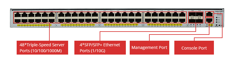
Network switches are always seen in data centers for data transmission. Many technical terms are used with the switches. Have you ever noticed that they are often described as Layer 2, Layer 3 or even Layer 4 switch? What are the differences among these technologies? Which layer is better for deployment? Let’s explore the answers through this post.
What Does “Layer” Mean?
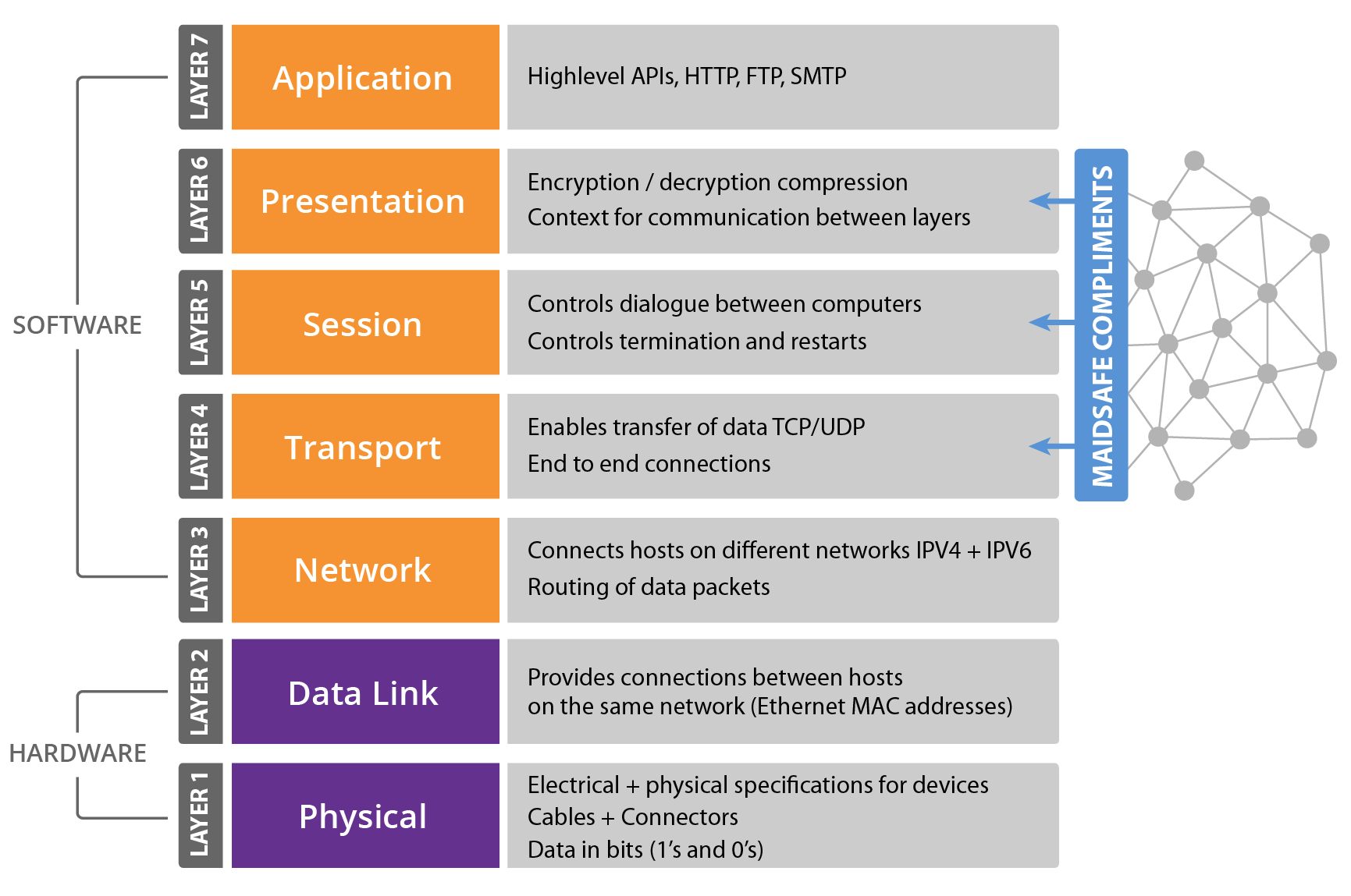
In the context of computer networking and communication protocols, the term “layer” is commonly associated with the OSI (Open Systems Interconnection) model, which is a conceptual framework that standardizes the functions of a telecommunication or computing system into seven abstraction layers. Each layer in the OSI model represents a specific set of tasks and functionalities, and these layers work together to facilitate communication between devices on a network.
The OSI model is divided into seven layers, each responsible for a specific aspect of network communication. These layers, from the lowest to the highest, are the Physical layer, Data Link layer, Network layer, Transport layer, Session layer, Presentation layer, and Application layer. The layering concept helps in designing and understanding complex network architectures by breaking down the communication process into manageable and modular components.
In practical terms, the “layer” concept can be seen in various networking devices and protocols. For instance, when discussing switches or routers, the terms Layer 2, Layer 3, or Layer 4 refer to the specific layer of the OSI model at which these devices operate. Layer 2 devices operate at the Data Link layer, dealing with MAC addresses, while Layer 3 devices operate at the Network layer, handling IP addresses and routing. Therefore, switches working on different layers of OSI model are described as Lay 2, Layer 3 or Layer 4 switches.
Switch Layers
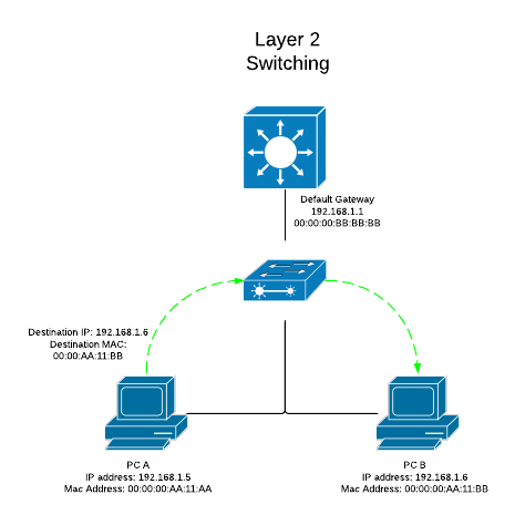
Layer 2 Switching
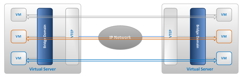
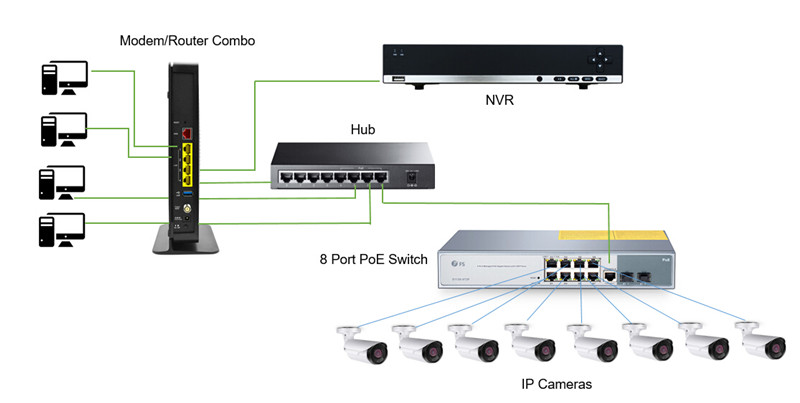
Layer 2 is also known as the data link layer. It is the second layer of OSI model. This layer transfers data between adjacent network nodes in a WAN or between nodes on the same LAN segment. It is a way to transfer data between network entities and detect or correct errors happened in the physical layer. Layer 2 switching uses the local and permanent MAC (Media Access Control) address to send data around a local area on a switch.
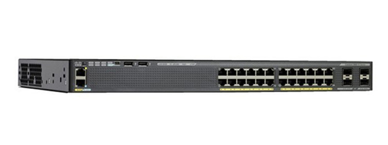
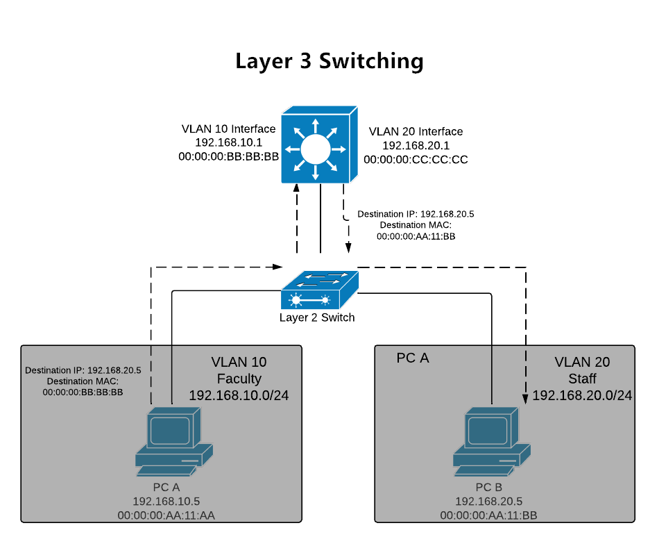
Layer 3 Switching
Layer 3 is the network layer in the OSI model for computer networking. Layer 3 switches are the fast routers for Layer 3 forwarding in hardware. It provides the approach to transfer variable-length data sequences from a source to a destination host through one or more networks. Layer 3 switching uses the IP (Internet Protocol) address to send information between extensive networks. IP address shows the virtual address in the physical world which resembles the means that your mailing address tells a mail carrier how to find you.
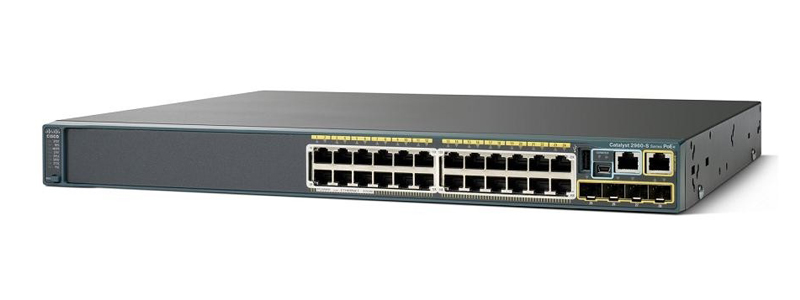
Layer 4 Switching
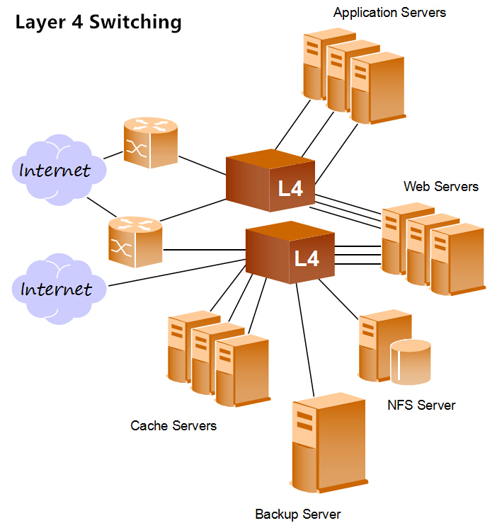
As the middle layer of OSI model, Layer 4 is the transport layer. This layer provides several services including connection-oriented data stream support, reliability, flow control, and multiplexing. Layer 4 uses the protocol of TCP (Transmission Control Protocol) and UDP (User Datagram Protocol) which include the port number information in the header to identify the application of the packet. It is especially useful for dealing with network traffic since many applications adopt designated ports.
” Also Check –What Is Layer 4 Switch and How Does It Work?
Which Layer to Use?
The decision to use Layer 2, Layer 3, or Layer 4 switches depends on the specific requirements and characteristics of your network. Each type of switch operates at a different layer of the OSI model, offering distinct functionalities:
Layer 2 Switches:
Use Case: Layer 2 switches are appropriate for smaller networks or local segments where the primary concern is local connectivity within the same broadcast domain.
Example Scenario: In a small office or department with a single subnet, where devices need to communicate within the same local network, a Layer 2 switch is suitable.
Layer 3 Switches:
Use Case: Layer 3 switches are suitable for larger networks that require routing between different subnets or VLANs.
Example Scenario: In an enterprise environment with multiple departments or segments that need to communicate with each other, a Layer 3 switch facilitates routing between subnets.
Layer 4 Switches:
Use Case: Layer 4 switches are used when more advanced traffic management and control based on application-level information, such as port numbers, are necessary.
Example Scenario: In a data center where optimizing the flow of data, load balancing, and directing traffic based on specific applications (e.g., HTTP or HTTPS) are crucial, Layer 4 switches can be beneficial.
Considerations for Choosing:
- Network Size: For smaller networks with limited routing needs, Layer 2 switches may suffice. Larger networks with multiple subnets benefit from the routing capabilities of Layer 3 switches.
- Routing Requirements: If your network requires inter-VLAN communication or routing between different IP subnets, a Layer 3 switch is necessary.
- Traffic Management: If your network demands granular control over traffic based on specific applications, Layer 4 switches provide additional capabilities.
In many scenarios, a combination of these switches may be used in a network, depending on the specific requirements of different segments. It’s common to have Layer 2 switches in access layers, Layer 3 switches in distribution or core layers for routing, and Layer 4 switches for specific applications or services that require advanced traffic management. Ultimately, the choice depends on the complexity, size, and specific needs of your network environment.
Conclusion
With the development of technologies, the intelligence of switches is continuously progressing on different layers of the network. The mix application of different layer switches (Layer 2, Layer 3 and Layer 4 switch) is a more cost-effective solution for big data centers. Understanding these switching layers can help you make better decisions.
Related Article:
Layer 2 vs Layer 3 Switch: Which One Do You Need? | FS Community