Tag Archives: fiber optic cable

What Are the Fiber Optic Cable Advantages and Disadvantages?

Share

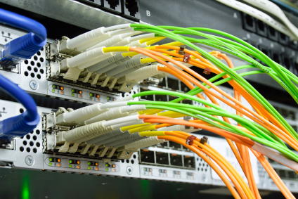
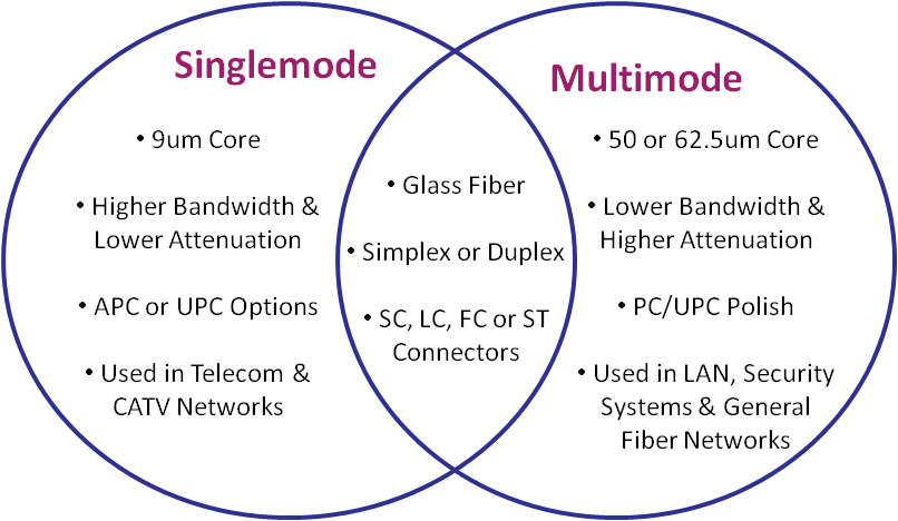
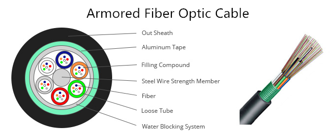
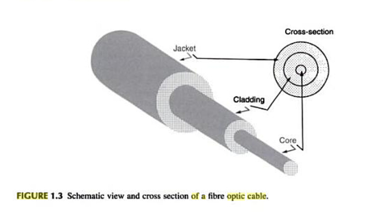
What are the fiber optic cable advantages and disadvantages? An optical fiber or fiber optic cable is a flexible, transparent fiber made by drawing glass, which are used most often as a means to transmit light between the two ends of the fiber and find wide usage in fiber-optic communications, where they permit transmission over longer distances and at higher bandwidths (data rates) than wire cables. Whether should I use optical fiber cables in my network? Single mode fiber or multimode fiber? Don’t worry, read through this post to learn both fiber optic cable advantages and disadvantages and then make a right choice.

optical fiber

Fiber Optic Cable Advantages and Disadvantages

Advantages of Optical Fiber Cable
  • Bandwidth

Fiber optic cables have a much greater bandwidth than metal cables. The amount of information that can be transmitted per unit time of fiber over other transmission media is its most significant advantage.

  • Low Power Loss

An optical fiber offers low power loss, which allows for longer transmission distances. In comparison to copper, in a network, the longest recommended copper distance is 100m while with fiber, it is 2km.

  • Interference

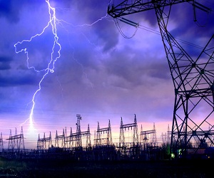
Fiber optic cables are immune to electromagnetic interference. It can also be run in electrically noisy environments without concern as electrical noise will not affect fiber.
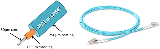
  • Size

In comparison to copper, a fiber optic cable has nearly 4.5 times as much capacity as the wire cable has and a cross sectional area that is 30 times less.

  • Weight

Fiber optic cables are much thinner and lighter than metal wires. They also occupy less space with cables of the same information capacity.  Lighter weight makes fiber easier to install.

  • Security

Optical fibers are difficult to tap. As they do not radiate electromagnetic energy, emissions cannot be intercepted. As physically tapping the fiber takes great skill to do undetected, fiber is the most secure medium available for carrying sensitive data.

  • Flexibility

An optical fiber has greater tensile strength than copper or steel fibers of the same diameter. It is flexible, bends easily and resists most corrosive elements that attack copper cable.

  • Cost

The raw materials for glass are plentiful, unlike copper. This means glass can be made more cheaply than copper.

Disadvantages of Optical Fiber Cable
  • Difficult to Splice

The optical fibers are difficult to splice, and there are loss of the light in the fiber due to scattering. They have limited physical arc of cables. If you bend them too much, they will break.

  • Expensive to Install

The optical fibers are more expensive to install, and they have to be installed by the specialists. They are not as robust as the wires. Special test equipment is often required to the optical fiber.

  • Highly Susceptible

The fiber optic cable is a small and compact cable, and it is highly susceptible to becoming cut or damaged during installation or construction activities. The fiber optic cables can provide tremendous data transmission capabilities. So, when the fiber optic cabling is chosen as the transmission medium, it is necessary to address restoration, backup and survivability.

  • Can’t Be Curved

The transmission on the optical fiber requires repeating at distance intervals. The fibers can be broken or have transmission losses when wrapped around curves of only a few centimeters radius.

Conclusion

Fiber optic cable has both advantages and disadvantages. However, in the long run, optical fiber will replace copper. In today’s network, fiber optic cable becomes more popular than before and is widely used. FS.COM, as a leading optics supplier, provides all kinds of optical fiber cables with high quality and low price for your option.

Related Article: What Are the Most Popular Fiber Optic Cable Types?

Related Article: What Kind of Fiber Patch Cord Should I Choose?

What’s the Difference: OM3 vs OM4

Share

OM3 and OM4 are two common types multimode fiber used in local area networks, typically in backbone cabling between telecommunications rooms and in the data center between main networking and storage area network (SAN) switches. Both of these fiber types are considered laser-optimized 50/125 multimode fiber, meaning they both have a 50μm micron diameter core and a 125μm diameter cladding, which is a special coating that prevents light from escaping the core. Both fiber types use the same connectors, the same termination and the same transceivers—vertical-cavity surface emitting lasers (VCSELs) that emit infrared light a 850 nanometers(nm). OM3 is fully compatible with OM4. With so many similarities, and often manufactured with the same color aqua cable jacket and connectors, it can be difficult to tell these two fiber types apart. So, what’s the difference between OM3 vs OM4? Do these two types fiber refer to the same thing?

OM3 vs OM4

What’s the Difference: OM3 vs OM4

In fact, the difference between OM3 vs OM4 fiber is just in the construction of the fiber optic cable. The difference in the construction means that OM4 cable has better attenuation and can operate at higher bandwidth than OM3. What is the reason of this? For a fiber link to work, the light from the VCSEL transceiver much have enough power to reach the receiver at the other end. There are two performance values that can prevent this—optical attenuation and modal dispersion.

Attenuation is the reduction in power of the light signal as it is transmitted (dB). Attenuation is caused by losses in light through the passive components, such as cables, cable splices, and connectors. As mentioned above the connectors are the same so the performance difference in OM3 vs OM4  is in the loss (dB) in the cable. OM4 fiber causes lower losses due its construction. The maximum attenuation allowed by the standards is shown below. You can see that using OM4 will give you lower losses per meter of cable. The lower losses mean that you can have longer links or have more mated connectors in the link.

Maximum attenuation allowed at 850nm: OM3 <3.5 dB/Km; OM4 <3.0 dB/Km

Light is transmitted at different modes along the fiber. Due to the imperfections in the fiber, these modes arrive as slightly different times. As this difference increases you eventually get to a point where the information being transmitted cannot be decoded. This difference between the highest and lowest modes is known as the modal dispersion. The modal dispersion determines the modal bandwidth that the fiber can operate at and this is the difference between OM3 and OM4. The lower the modal dispersion, the higher the modal bandwidth and the greater the amount of information that can be transmitted. The modal bandwidth of OM3 and OM4 is shown below. The higher bandwidth available in OM4 means a smaller modal dispersion and thus allows the cable links to be longer or allows for higher losses through more mated connectors. This gives more options when looking at network design.

Minimum Fiber Cable Bandwidth at 850nm: OM3 2000 MHz·km; OM4 4700 MHz·km

Choose OM3 or OM4?

Since the attenuation of OM4 is lower than OM3 fiber and the modal bandwidth of OM4 is higher than OM3, the transmission distance of OM4 is longer than OM3. Details are shown in the table below. According to your network scale, to choose a more suitable cable type.

Fiber Type 100BASE-FX 1000BASE-SX 10GBASE-SR 40GBASE-SR4 100GBASE-SR4
OM3 2000 Meters 550 Meters 300 Meters 100 Meters 100 Meters
OM4 2000 Meters 550 Meters 400 Meters 150 Meters 150 Meters

Since OM4 performs better than OM3 cables, usually, OM4 cable is about twice as expensive as OM3 cable. This may be a big limited factor of OM4 cables’ application. However, if you choose to shop in Fiberstore, you may get much cheaper OM4 fiber nearly the same as the OM3 fiber. Price of different types OM3 and OM4 cables in Fiberstore is listed in the table below:

Fiber Type 3m Standard LC duplex 3m Armored LC duplex 3m HD LC duplex 3m Standard MTP
OM3 US$ 3.30 US$ 7.20 US$ 22.00 US$ 49.00
OM4 US$ 4.00 US$ 8.00 US$ 24.00 US$ 54.00

Either OM3 or OM4 cable can satisfy your unique cabling needs. Just choose the most suitable one for your network to cost less and achieve more.

Related Article: OM3 OR OM4 Cable Which One Do You Need?

Related Article: Multimode Fiber Types: OM1 vs OM2 vs OM3 vs OM4 vs OM5

What’s the Difference Between Twisted Pair vs Coaxial Cable vs Fiber Optic

Share

As we know, communication system usually uses a wire or cable to connect sending and receiving devices. Currently, the most common network cable types deployed in communication system are twisted pair vs coaxial cable vs fiber optic cable. Since each of them can be equally applied into network communication, what’s the difference between twisted pair vs coaxial cable vs fiber optic? This article may give some answers.

Twisted Pair Cables
Twisted PairTwisted pair cable consists of a pair of insulated wires twisted together, which is adapted in the field of telecommunication for a long time. With the cable twisting together, it helps to reduce noise from outside sources and crosstalk on multi-pair cables. Basically, twisted pair cable can be divided into two types: unshielded twisted-pair (UTP) and shielded twisted-pair (STP). The former serves as the most commonly used one with merely two insulated wires twisted together. Any data communication cables and normal telephone cables belong to this category. However, shielded twisted pair distinguishes itself from UTP in that it consists of a foil jacket which helps to prevent crosstalk and noise from outside source. It is typically used to eliminate inductive and capacitive coupling, so it can be applied between equipment, racks and buildings. There exist following several different types of twisted pair cables:

Twisted Pair Cables

Coaxial Cables
Coaxial-Cable
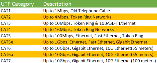
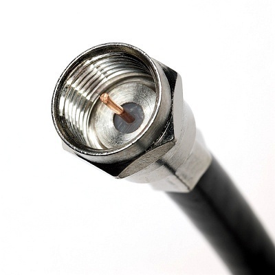
Coaxial cable acts as a high-frequency transmission cable which contains a single solid-copper core. A coaxial cable has over 80 times the transmission capability of the twisted-pair. It is commonly used to deliver television signals and to connect computers in a network as well, so people may get more familiar with this kind of network cable. There are two coaxial cables: 75 Ohm and 50 Ohm. What’s the application of them respectively?

  • 75 Ohm coaxial cable

The primary use of a 75 Ohm cable is to transmit a video signal. One of the typical applications is television signals over network cable, sometimes called signal feed cables. The most common connector used in this application is a Type F. Another application is video signals between components such as DVD players, VCRs or Receivers commonly known as audio/video (A/V) cables. In this case BNC and RCA connectors are most often found. In both of these applications RG59 with both solid center conductor (RG59B/U) and stranded center conductor (RG59A/U) as well as RG6 are often found.

75 Ohm coaxial cable

  • 50 Ohm coaxial cable

The primary use of a 50 Ohm coaxial cable is transmission of a data signal in a two-way communication system. Some common applications for 50 Ohm coaxial cable are computer ethernet backbones, wireless antenna feed cables, GPS (Global Positioning Satellite) antenna feed cables and cell phone systems.

50 Ohm coaxial cable (1)

Fiber Optic Cable

Picture of optical cables pluged in network server

Computing and data communications are fast-moving technologies. There comes a new generation of transmission media—fiber optic cable. It refers to the complete assembly of fibers, which contain one or more optical fibers that are used to transmit data. Each of the optical fiber elements is individually coated by plastic layers and contained in a protective tube. Fiber optic cable transmits data as pulses of light go through tiny tubes of glass, the transmission capacity of which is 26,000 times higher than that of twisted-pair cable. When comparing with coaxial cables, fiber optic cables are lighter and reliable for transmitting data. They transmit information using beams of light at light speed rather than pulses of electricity.

Nowadays, there are two fiber optic cable types widely adopted in the field of data transfer—single mode fiber optic cable and multimode fiber optic cable. A single-mode optical fiber is a fiber that has a small core, and only allows one mode of light to propagate at a time. So it is generally adapted to high speed, long-distance applications. While a multimode optical fiber is a type of optical fiber with a core diameter larger than the wavelength of light transmitted and it is designed to carry multiple light rays, or modes at the same time. It is mostly used for communication over short distances because of its high capacity and reliability, serving as a backbone application in buildings.

Singlemode-vs-Multimode Fiber Optic Cable

Conclusion of Twisted Pair vs Coaxial Cable vs Fiber Optic
As the technology in the field of the network is developing rapidly, network cable seems to become the trend for the increasing demand of the market. After learning the difference between twisted pair vs coaxial cable vs fiber optic, we know how to choose network cable. However, whether to choose twisted pair cables, coaxial cables or fiber optic cables still depends heavily on applications, which is subject to the cost, transmission distance and performance.

Related Article: Which Patch Cable Should I Choose for My Optical Transceiver?

Fiber Optic Cable vs Twisted Pair Cable vs Coaxial Cable

What Are the Most Popular Fiber Optic Cable Types?

Share

Recently, as the fiber optic cable is used more and more widely than earlier years, people also know more about the fiber optic cables than before. Usually, we learn that the fiber optic cables are divided into two basic types: single mode fiber and multimode fiber. However, according to the fiber optic cable is used for indoor or outdoor, there are many other fiber types too. These fiber optic cable types are all the popular ones which are available in the current market. Then I will introduce these various fiber types to you in this article.

Fiber Optic Cable Types: Indoor Fiber Optic Cables

In terms of indoor fiber optic cables, distribution cable, breakout cable, ribbon cable and LSZH cable are some popular types. Distribution cable and breakout cable all contain several jacketed simplex optical fibers packaged together inside an outer jacket, but in distribution fiber optic cable, tight buffered fibers are bundled together, with only the outer cable jacket of the cable protecting them. Besides, buffered fiber in distribution cable is 900 µm, which is smaller in size and costs less than breakout cable. Distribution cable is usually installed in intra-building backbone and inter-building campus locations. And breakout fiber optic cable is suitable for short riser and plenum applications. Ribbon cable includes up to 12 fibers contained side by side within a single jacket and is often used for network applications and data centers. LSZH cables are offered as an alternative for halogen-free applications. They are less toxic and slower to ignite which makes them a good choice for many internal installations.

breakout fiber optic cable types

Fiber Optic Cable Types: Outdoor Fiber Optic Cables

In terms of indoor fiber optic cables, however, tight buffered cables, loose tube cables, armored cables and submarine cables are some common popular fiber cable types. Among them, submarine fiber optic cables become more and more popular in recent years. These cables are used in fresh or salt water. To protect them from damage by fishing trawlers and boat anchors they have elaborately designed structures and armors. Other cable has armors is armored cable. Armored fiber optic cable includes an outer armor layer for mechanical protection and to prevent damage. They can be installed in ducts or aerially, or directly buried underground. Armor is surrounded by a polyethylene jacket. Tight buffered cable and loose tube cable are two early common outdoor fiber cables. Tight buffered cables have riser and plenum rated versions. These cables are flexible, easy to handle and simple to install. In loose tube cables, tube encloses multiple coated fibers that are surrounded by a gel compound that protects the cable from moisture in outside environments. This cable is restricted from indoor use, typically allowing entry not to exceed 50 feet.

Armored Fiber Optic Cable Types

All these indoor and outdoor fiber optic cables play an important role in optical network. As they have different characteristics, they have different applications too. For this reason, when you choose fiber optic cables, you must take their usability into consideration. For more information, you can visit Fiberstore, which designs and manufactures all these popular fiber optic cables.

Related Article: Fiber Optic Cable vs Twisted Pair Cable vs Coaxial Cable

Armored Fiber Optic Cable

Share

Definition of armored fiber optic cable
Armored Fiber Optic Cable, just as the name implies, is that there is a layer of additional protective metal armoring of the fiber optic cable.
Armored Fiber CableFunction
Armored fiber cable plays a very important role in long-distance line of fiber optic cable. A layer of metal armoring in the scarf-skin of fiber optic cable protects the fiber core from rodent, moist and erosion.

Classification
According to the place of use, there are indoor armored fiber optic cables and outdoor armored fiber optic cables.

Indoor armored fiber optic cable
Indoor armored fiber optic cable is mainly used in interior, so it must be flexible and can be installed in the corner and some narrow places. Besides, indoor armored fiber optic cable experiences less temperature and mechanical stress, but they have to be fire retardant, emit a low level of smoke in case of burning. And indoor armored fiber cables must allow a small bend radius to make them be amendable to vertical installation and handle easily.

Indoor armored fiber optic cable can be divided into simplex armored fiber optic cable and duplex armored fiber optic cable. The main difference is that simplex armored fiber optic cable is the cable that not contains stainless steel wire woven layer, and duplex armored fiber optic cable is the cable that contains stainless steel hose and stainless steel wire woven which are of compressive property, resistance to deflection, rodent resistance, anti-torque and so on.

Outdoor armored fiber optic cable
Outdoor armored fiber optic cables are made to protect the optical fiber to operate safely in complicated outdoor environment. Most armored outdoor fiber cables are loose buffer design, with the strengthen member in the middle of the whole cable, the loose tubes surround the central strength member.

Outdoor armored fiber optic cable can be divided into light armored fiber optic cable and heavy armored fiber optic cable. Light armored fiber optic cable is with steel tape and aluminium tape which can strengthen rodent protection. Heavy armored fiber optic cable is equipped with a circle of steel wire, and usually used in riverbed and seabed.

Installation
There are two installation methods of armored fiber optic cable. One is buried directly in the ground, and the other is aerial optical cable.

For direct burial fiber cable, armored fiber optic cable is in the position to resist external mechanical damage, prevent erosion and resist rodent. In addition, because of different soil and environment, the depth of burying under the ground is about between 0.8m-1.2m.

On the other hand, aerial optical cable is the optical cable that hanging on the pole. This kind of installation way of armored fiber optic cable can prevent fiber core from any kind of severe environment, such as typhoon, ice, and people or animals. Aerial armored optical cable mostly uses central loose tube armored fiber optic cable (GYXTW) and stranded loose tube armored fiber optic cable (GYTA). The features of GYXTW are that can contain up to 12 fiber cores, the loose tube is centrally situated with good excess length and minimizes the influence of lateral crush, and double wire as strength member provides excellent strain performance. GYTA is suitable for installation for long haul communication and LANs, especially suitable for the situation of high requirements of moisture resistance. GYTA is with compact structure; the cable jacket is made of strong Polyethylene. This armored fiber optic cable features the good mechanical and temperature performance. GYTA is also with high strength loose tube that is hydrolysis resistant and the optical cable filling materials ensure high reliability, its APL makes the cable crush resistant and moisture proof. The GYTA fiber optic cable is available from 2 cores to 144 cores.

Some Common Types of Indoor Cables

Share

Optical fiber cables for indoor cabling are used for the construction of horizontal subsystem and SCS building backbone cabling subsytems. They differ form cables used for outdoor cabling by two key parameters.

Indoor fiber optic cable is tight buffer design, usually they consist of the following components inside the cable, the FRP which is non-metallic strengthen member, the tight buffer optical fiber, the Kevlar which is used to further strength the cable structure, making it resist high tension, and the cable outer jacket. The trend is to use LSZH or other RoHS compliant PVC materials to make the cable jacket; this will help protect the environment and the health of the end users.

Indoor Cables

Cables for indoor applications include the following:

* Simplex cables
* Duplex cables
* Multifiber cables
* Heavy-, light-, and plenum-duty cables
* Breakout cables
* Ribbon cables

Although thes categories overlap, they represent the common ways of referring to fibers. Figure 7-5 shows cross sections of several typcial cables types.

Simplex Cables

A simplex fiber cable consists of a single strand of glass of plastic fiber. Simplex fiber is most often used where only a single transmit and/or receive line is required between devices or when a multiplex data signal is used (bi-directional communication over a single fiber).

Duplex Cables

A duplex fiber cable consists of two strands of glass or plastic fiber. Typically found in a “zipcord” construction format, this cable is most often used for duplex communication between devices where a separate transmit and receive are required.

Duplex cable is used instead of two simplex cables for aesthetics and convenience. It is easier to handle a single duplex cable, there is less chance of the two channels becoming confused, and the appearance is more pleasing. Remember, the power cord for your lamp is a duplex cable that could eaily be two separate wires. Does a single duplex cord in the lamp not make better sense? The same reasoning prevails with fiber optic cables.

Loose Tube Cables

loose tube cable

The loose tube variety contains one or more hard buffer tubes, which house between 1 and 12 coated fibers. The hard buffer tubes are also filled with a gel to provide vibration and moisture protection for the fibers. The fibers lie loosely in the tubes, which are wound into the cable in a reversing helical fashion and are actually longer than the outer sheath of the cable. This arrangement allows for a small amount of stretch in the outer sheath when installing the cable. Loose tube cable is used most often in OSP construction because it is designed for a tough outdorr environment use. See Figure-1 for the physical make-up of a typical loose tube cable.

Breakout Cables

Breakout cabke

Breakout cables have several individual simplex cables inside an outer jacket. The breakout cables shown in Figure 2 use two dielectric fillers to keep the cables positioned, while a Mylar wrap surrounds the cables/fillers. The outer jacket includes a ripcord to make its removal fast and easy. The point of the breakout cable is to allow the cable subunits inside to be exposed easily to whatever length is needed. Breakout cables are typically available with two or four fibers, although larger cables also find use.

Ribbon Cables

ribbon cable

Ribbon cable uses a number of fibers side by side in a single jacket. Originally, Ribbon fiber cable was used for outdoor cables (see Figure 3). Today they also find use in premises cabling and computer applications. The cables, typically with up to 12 fibers, offer a very small cross section. They are used to connect equipment within cabinets, in network applications, and for computer data centers. In addtion, they are comatible with multifiber array connectors. Ribbon cables are available in both multimode and single-mode versions.

Related Article:  Which Patch Cable Should I Choose for My Optical Transceiver?

Fiber Optic Cable Circuit Also Need Lightning Protection

Share

Some time ago a customer bought the fiber optic cable from fs.com, but he asked me if it can be used in frequent areas of lightning and if he needs to lightning protection. Well, As for this problem, I give the customer this explanation.

Suitable cable barrier property makes its lightning protection is not so obvious as coax and open cable circuit. And in the process of rapid development of fiber optic cables, safety grounding is often misunderstood and even forgotten. With a large number of adoptions of optical fiber cable, the situation of the fiber optical cable circuit from lightning often occurs these years. Fiber optic cable circuit has a great deal of capacity and the easiest links that be lightning struck is buried links, and it is also difficult to repair, so once it is in trouble, will cause huge losses. This page mainly introduces the fiber optic cable circuit lightning protection.

Fiber Optic Cable Lightning Protection

Fiber optic cable has no electrical conductivity, can protect from impact current, but in order to male high capacity optical cables from environmental events, fiber optic cables must have armored cable components and when electric line close to short and a lighting strike, people will feel current ac or surge current, harm the safety or damage the link road equipment. Related product: adss fiber.

Lightning has the trend to find the minimum impedance path to bleed thundercloud charge opposite charges neutralize underground. When lightning the land or buildings, lightning point potential while the cable extends to the very far, far end can be regarded as a potential 0, so the potential of lightning strikes near the cable is also regarded as 0. Such colony formation and fiber optic cable between the lightning point of great potential difference, the potential difference exceeds the compressive strength of Jiang Lei point between the outer sheath of the cable will breakdown the outer sheath formed from lightning point to the metal components arc channel, so a lot of lightning current flock to the cable, causing serious damage to the cable. ? It is the time to use optical fiber cable st termination kit. Cable lines in the construction inevitably damage PE (polyethylene) jacket, another rat-bite, external staff may cause the cable exposed metal components. These points will be easy to expose a strong electrical charge is introduced or lightning cable, causing damage.

According to relevant data show that in the following cases, cable lines susceptible to lightning strikes:

  • Metal sheaths, strengthen the core or the insulation lower copper cable.
  • Mutation terrain, soil resistivity changes in the larger area.
  • Cable trees or tall buildings with a single gauge are not enough time.

According to the above analysis, the same cable line to be concerned about its main work. Fiber optic cable lines for lightning protection, can target local weather and terrain and other natural conditions, a targeted manner. After analysis of a few lightning cable, I found that the cable line construction and maintenance should pay attention to the following questions.

aerial cable

First, as for aerial cables, one of the outdoor fiber optic cable, the connector box usually has to the structure of the core can be broken even, whether using electrical connected or disconnected, metal pressure plate structure is superior to the self-contained bolt connection, and the self-contained horizontal hole is better than vertical slot structure, it is a problem that should be paid attention to when choosing connector box.

Second, for underground cable lines protection, first of all, station grounding method, in the joint of the metal part of the cable shall be connected, the relay length of cable, moisture proof layer, strengthens core armored layer connected state.In both ends (station), the wrong layer, reinforcement, they can moisture proof layer should be through the arrester grounding.

Related Article:  Which Patch Cable Should I Choose for My Optical Transceiver?

Core And Cladding In Fiber Optic Cable

Share

Fiber optic cables transmit data through very small cores at the speed of light. Significantly different from copper cables, fiber optic cables offer high bandwidths and low losses with the help of the core and cladding. And it allows high data-transmission rates over long distances. Light propagates throughout the fiber cables according to the principle of total internal reflection.

There are three common types of fiber optic cables: single-mode, multimode, and graded-index. Each has its advantages and disadvantages. There also are several different designs of fiber optic cables, each made for different applications. In addition, new fiber optic cables with different core and cladding designs have been emerging; these are faster and can carry more modes. While fiber optic cable are used mostly in communication systems, they also have established medical, military, scanning, imaging, and sensing applications. They are also used in optical fiber devices and fiber optic lighting.

Fiber optic cable is a filament of transparent material used to transmit light, as shown in Figure 1.2. Virtually all fiber optic cables share the same fundamental structure. The centre of the cable is referred to as the core. It has a highter refractive index than the cladding, which surrounds the core. The contact surface between the core and the cladding creates an interface surface that guides the light; the difference between the refractive index of the core and cladding is what causes the mirror like interface surface, which guides light along the core. Light bounces through the core from one end to the other according to the principle of total internal reflection, as explained by the laws of light. The cladding is then covered with a protective plastic or PVC jacket. The diameters of the core,cladding, and jacket can vary widely; for a single fiber optic cable can have core, cladding, and jacket diameters of 9, 125, and 250 um, respectively.

Figure 1.3 shows the structure of a typical fiber optic cable. The cores of most fiber optic cables are made from pure glass, while the cladding are made from less pure glass. Glass fiber optic cable has the lowest attenuation over long distances but comes at the highest cost. A pure glass fiber optic cable has a glass cladding. Fiber optic cable core and cladding may be made from plastic, which is not as clear as glass but is more flexible and easier to handle. Compared with other fiber cables, Plastic Optical Fiber Cable is limited in power loss and bandwidth. However, they are more affordable, easy to use, and attractive in applications where high bandwidth or low loss is not a concern. A few glass fiber cable cores are clad with plastic. Their performance, though not as good as all-glass fiber cables, is quite respectable.

core and cladding in fiber optic cable

The jacket is made from polymmer (PVC, plastic, etc.) to protect the core and the cladding from mechanical damage. The jackets has several major attributes, including bending ability, abrasion resistance, static fatigue protection, toughness, moisture resistance, and the ability to be stripped. Fiber optic cable jackets are made in different colours for colour-coding identification. Some optical fibers are coated with a copper-based alloy that allows operation at up to 700 and 500℃ for short and long periods, respectively.

Fiberstore is a leading supplier of Fiber Optic Cable and components into the umbilical and towed array products for the oil & gas sector. The key technology for these products is Fiberstore’s patented stainless steel fiber optic tube technology which packages the optical fiber in the best possible way resulting in a robust, compact product that is suitable for the high pressure of the subsea environment. Fiberstore will customize the design to meet your needs to include different fiber counts, fiber types, metal types, tube sizes, belting materials, armor type, armor size, armor count, encapsulation types, color, print, packaging and length.

Related Article:  Which Patch Cable Should I Choose for My Optical Transceiver?

Related Article:  The Advantages and Disadvantages of Optical Fiber

More Characteristics of Fiber Optic Cable

Share

When light from a source is sent through a fiber-optic cable, the ligth wave both bounces around inside the cable and passes through the cable to the outlet protective jacket. When a light signal inside the cable bounces off the cable wall and back into the cable, this is called reflection. When a light signal passes from the core of the cable into the surrounding material, this is called refraction. Figure 3-9 demonstrates the differece between reflection and refraction.

Light can be transmitted through a fiber-optic cable using two basic techniques. The first technique, called single-mode transmission, requires the use of a very thin fiber-optic cable and a very focused light source, such as a laser. When a laser is fired down a narrow fiber, the light follows a tight beam, and so there is less tendency for the light wave to reflect or refract. Thus, this technique allows for a very fast signal with little signal degradation (and thus less noise) over long distances. Because lasers are used as the light source, single-mode transmission is a more expensive techique than the second fiber-optic cable signaling techique. Any application that involves a large amount of data transmitted at high speeds is a candidate for single-mode transmission.

The second signaling technique, called multimode transmission, uses a slightly thicker fiber cable and an unfocused light source, such as an LED. Because the light source is unfocused, the light wave experiences more refraction and reflection (i.e, noise) as it propagates through the wire. This noise results in signals that cannot travel as far or as fast as the signals generated with the single-mode technique. Correspondingly, multimode transmission is less expensive than single-mode transmission. Local area networks that employ fiber-optic cables often use multimode transmissions.

Single-mode and multimode transmission techniuqes use fiber-optic cable with different characteristics. The core of single-mode fiber-optic cable is 8.3 microns wide, and the material surrounding the fiber – the cladding – is 125 microns wide. Hence, single-mode fiber optic cable is labeled 8.3/15 cable. The core of multimode fiber optic cable is most commonly 62.5 microns wide, and the cladding is 125 microns. Multimode fiber optic cable is labeled 62.5/125 cable. Othe sizes of multimode fiber optic cable include 50/125 and 100/140 microns.

Bulk fiber optic cable comes in lots of types, depending on where it will be installed. Where to buy fiber optic cable? As the best OEM fiber optic cable manufacturer, Fiberstore provides a wide range of quality optical fiber cables with detailed specifications displayed for your convenient selecting. Per foot price of each fiber cable is flexible depending on the quantities of your order, making your cost of large order unexpected lower. Customers can also have the flexibility to custom the cable plant to best fit their needs. Only fiber cable that meets or exceeds industry standards is used to ensure quality products with best-in-class performance. Fiberstore offers an extensive line of off the shelf bulk fiber optic cable to address your fiber installation needs. We stock 62.5/125, 50/125, and 9/125 bulk fiber optic cable in simplex, duplex (zip cord), breakout, and distribution styles.

Related Article:  Which Patch Cable Should I Choose for My Optical Transceiver?

Patch Cord Optical Power Loss Measurement

Share

Measurement of fiber optic cable loss is an established practice that has been performed for many years. However, over time, the performance of fiber optic equipment has been improved, so occasionally it is useful to perform a practical re-assessment of the accuracy of these measurements.

Multi-mode patch cord optical loss power measurement is performed using the steps described in ANSI/TIA-526-14, method A. The fiber optic patch cord is substituted for the cable plant. Because patch cords are typically no longer than 5 m, the loss for the optical fiber is negligible and testing can be performed at 850 nm or 1300 nm. The loss measured in this test is the loss for the patch cords connector pair. ANSI/TIA-568-C.3 states that the maximum loss for a connector pair is 0.75 dB.

After setting up the test equipment as described in ANSI/TIA-526-14, method A, clean and inspect the connectors at the ends of the patch cords to be tested. Verity that your test jumpers have the same optical fiber type and connectors as the patch cords you are going to test. The transmit jumper should have a mandrel wrap or modal conditioner depending on the revision ANSI/TIA-526-14 being used for testing. Ensure that there are no sharp bends in the test jumpers or patch cord during testing.

Because both patch cord connectors are easily accessible, optical power loss should be measured in both directions. The loss for the patch cord is the average of the two measurements. If the loww for the patch cord exceeds 0.75dB in either direction, the patch cord needs to be repaired or replaced.

For testing the loss of a patchcord, you only need an 850 nm LED light source for multimode cable or 1310 laser for singlemode, a fiber optic power meter and some reference patchcords. Just remember that the patchcords used for references in testing must be good for tests to be valid, so you test them as you would other patchcords, just more often.

Testing patch cords is similar to testing any fiber optic cable. Use one reference patch cord to set a 0 dB reference. Connect a patch cord to test to the reference patch cord with a mating adapter. Connect the power meter to the other end of the patch cord and measure the loss. Since the length of the fiber is short, the loss contribution of the fiber is ignoble. And since one end of the cable is attached to the power meter, not another cable, you only measure the loss of the one connection between the reference cable and the cable under test, so you can test each connector individually.

To complete the testing of the patch cord, reverse the cable you are testing to check the connector on the other end. Sometimes you will find one bad connector and can replace it to make the patch cord useful again. But often the cost of replacing the connector may be higher than replacing the patch cord itself.

If your test equipment has different connectors than the patchcords you are testing, you will need hybrid reference cables with connectors compatible with the equipment on one end and the patchcord connectors on the other end. You will also need the correct connector adapters for your power meter.

Obviously, all reference cables used for testing must have high quality connectors to get reliable test results. Use this same method to test your reference cables against each other and discard any with high losses, usually those with losses over 0.5 dB.