Tag Archives: EDFA

From O to L: the Evolution of Optical Wavelength Bands

Share

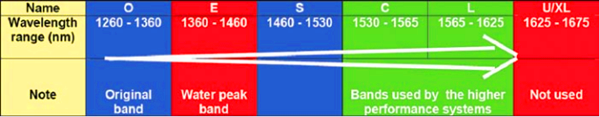
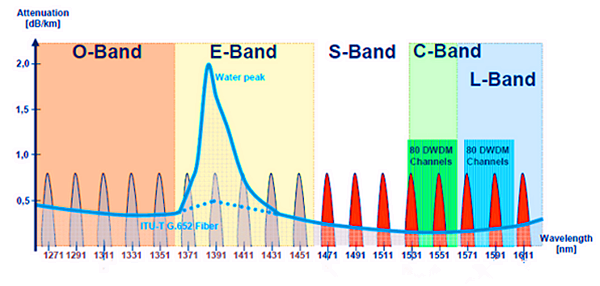
In optical fiber communications system, several transmission bands have been defined and standardized, from the original O-band to the U/XL-band. The E- and U/XL-bands have typically been avoided because they have high transmission loss regions. The E-band represents the water peak region, while the U/XL-band resides at the very end of the transmission window for silica glass.

Optical Wavelength Bands

Intercity and metro ring fiber already carry signals on multiple wavelengths to increase bandwidth. Fibers entering the home will soon do the same. Now there are several types of optical telecom systems have been developed, some based on time division multiplexing (TDM) and others on wavelength division multiplexing (WDM), either dense wavelength division multiplexing (DWDM) or coarse wavelength division multiplexing (CWDM). This article may represent the evolution of optical wavelength bands mainly by describing these three high-performance systems.

Dense Wavelength Division Multiplexing
DWDM systems were developed to deal with the rising bandwidth needs of backbone optical networks. The narrow spacing (usually 0.2 nm) between wavelength bands increases the number of wavelengths and enables data rates of several Terabits per second (Tbps) in a single fiber.

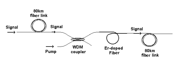
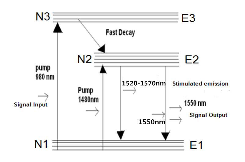
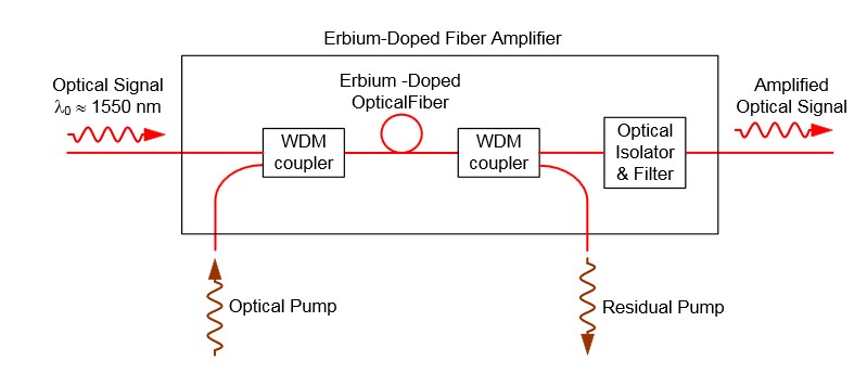
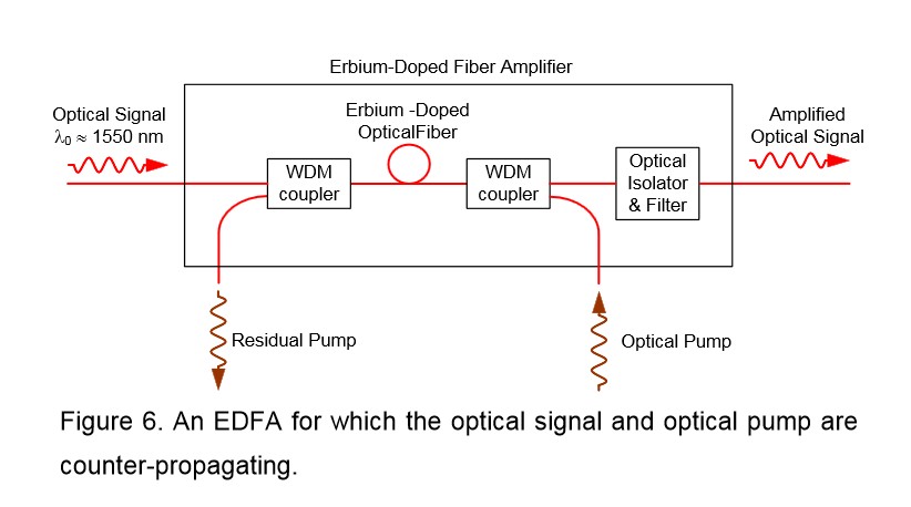
These systems were first developed for laser-light wavelengths in the C-band, and later in the L-band, leveraging the wavelengths with the lowest attenuation rates in glass fiber as well as the possibility of optical amplification. Erbium-doped fiber amplifiers (EDFAs, which work at these wavelengths) are a key enabling technology for these systems. Because WDM systems use many wavelengths at the same time, which may lead to much attenuation. Therefore optical amplification technology is introduced. Raman amplification and erbium-doped fiber amplifiers are two common types used in WDM system.

DWDM

In order to meet the demand for “unlimited bandwidth,” it was believed that DWDM would have to be extended to more bands. In the future, however, the L-band will also prove to be useful. Because EDFAs are less efficient in the L-band, the use of Raman amplification technology will be re-addressed, with related pumping wavelengths close to 1485 nm.

Coarse Wave Division Multiplexing
CWDM is the low-cost version of WDM. Generally these systems are not amplified and therefore have limited range. They typically use less expensive light sources that are not temperaturestabilized. Larger gaps between wavelengths are necessary, usually 20 nm. Of course, this reduces the number of wavelengths that can be used and thus also reduces the total available bandwidth.

CWDM

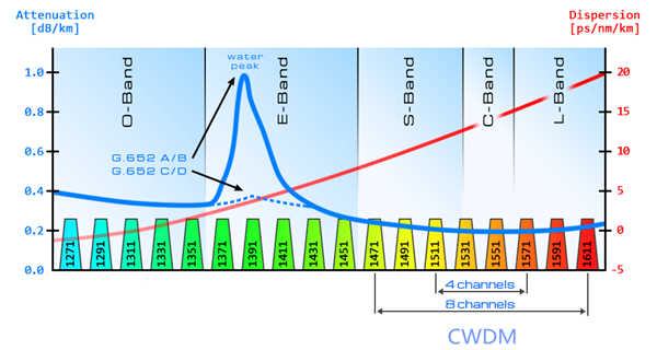
Current systems use the S-, C- and L-bands because these bands inhabit the natural region for low optical losses in glass fiber. Although extension into the O and E-band (1310 nm to 1450 nm) is possible, system reach (the distance the light can travel in fiber and still provide good signal without amplification) will suffer as a result of losses incurred by use of the 1310 nm region in modern fibers.

Time Division Multiplexing
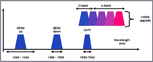
TDM systems use either one wavelength band or two (with one wavelength band allocated to each direction). TDM solutions are currently in the spotlight with the deployment of fiber-to-the-home (FTTH) technologies. Both EPON and GPON are TDM systems. The standard bandwidth allocation for GPON requires between 1260 and 1360 nm upstream, 1440 to 1500 nm downstream, and 1550 to 1560 nm for cable-TV video.

To meet the rise in bandwidth demand, these systems will require upgrading. Some predict that TDM and CWDM (or even DWDM) will have to coexist in the same installed network fibers. To achieve this, work is underway within the standardization bodies to define filters that block non-GPON wavelengths to currently installed customers. This will require the CWDM portion to use wavelength bands far away from those reserved for GPON. Consequently, they will have to use the L-band or the C- and L-bands and provided video is not used.

tdm

Conclusion
In each case, sufficient performance has been demonstrated to ensure high performance for today’s and tomorrow’s systems. From this article, we know that the original O-band hasn’t satisfied the rapid development of high bandwidth anymore. And the evolution of optical wavelength bands just means more and more bands will be called for. In the future, with the growth of FTTH applications, there is no doubt that C- and L-bands will play more and more important roles in optical transmission system. Fiberstore offer all kinds of products for WDM optical network, such as CWDM/DWDM MUX DEMUX and EDFA. For more information, please visit www.fs.com.

Erbium Doped Fiber Amplifier (EDFA) Used in WDM System

Share

The capacity of fiber optical communication systems has undergone enormous growth during the last few years in response to huge capacity demand for data transmission. With the available wavelength division multiplexing (WDM) equipment, commercial system can transport more than 100 channels over a single fiber. However, increasing the number of channels in such systems will eventually result in the usage of optical signal demultiplexing components with greater values of optical attenuation. Besides, when transmitted over long distances, the optical signal is highly attenuated. Therefore, to restore the optical power budget, it is necessary to implement optical signal amplification. This article may mainly tell you  why EDFA is used in WDM system and how does it work.

Why Use EDFA in WDM System?

EDFA stands for erbium-doped fiber amplifiers, which is an optical amplifier that uses a doped optical fiber as a gain medium to amplify an optical signal. EDFA has large gain bandwidth, which is typically tens of nanometers and thus actually it is enough to amplify data channels with the highest data rates. A single EDFA may be used for simultaneously amplifying many data channels at different wavelengths within the gain region. Before such fiber amplifiers were available, there was no practical method for amplifying all channels between long fiber spans of a fiber-optic link. There are practically two wavelength widows C-Band (1530nm-1560nm) and L-Band (1560nm-1600nm). EDFA can amplify a wide wavelength range (1500nm-1600nm) simultaneously, which just satisfies the DWDM application, hence it is very useful in WDM for amplification.

How Does EDFA Work ?

The basic configuration for incorporating the EDFA in an optical fiber link is shown in the picture below. The signals and pump are combined through a WDM coupler and launched into an erbium-doped fiber (EDF). The amplified output signals can be transmitted through 60-100km before further amplification is required.

EDFA
Erbium-doped fiber is the core technology of EDFA, which is a conventional silica fiber doped with erbium ions as the gain medium. Erbium ions (Er3+) are having the optical fluorescent properties that are suitable for the optical amplification. When an optical signal such as 1550nm wavelength signal enters the EDFA from input, the signal is combined with a 980nm or 1480nm pump laser through a wavelength division multiplexer device. The input signal and pump laser signal pass through erbium-doped fiber. Here the 1550nm signal is amplified through interaction with doped erbium ions. This can be well understood by the energy level diagram of Er3+ ions given in the following figure.

EDFA

Where to Buy EDFA for Your WDM System ?

To ensure the required level of amplification over the frequency band used for transmission, it is highly important to choose the optimal configuration of the EDFAs. Before you buy a EDFA, keep in mind that the flatness and the level of the obtained amplification, and the amount of EDFA produced noise are highly dependent on each of the many parameters of the amplifier. Fiberstore provide many kinds of EDFAs, especially the DWDM EDFAs (shown in the picture below), which have many output options (12dBm-35dBm). Besides, they are very professional in optical amplifiers. Whatever doubts you have, they can give a clear reply.

EDFA

Ultra-High-Power Optical Amplifier for FTTH – EYDFA

Share

Background

While the Cable Modem, xDSL, and other forms of broadband access are booming in recent years, Fiber To The Home (FTTH) access is also gradually becoming a project that people are very interested in. The FTTH will eventually realize the “three networks in one” of Telephone, CATV and Internet, when the speed of data transmission can be more than 100 Mbps (200 times faster than the commonly used dial-up Internet access) and bring homes high-definition TV movies and fast online office, etc. FTTH can also solve the problem such as the quality of phone calls, the definition of television and so on.

From the perspective of the world’s situation, the FTTH’s promotion of South Korea and Japan has entered a rapid growth period; North America and Europe has begun to start which brings an optimistic outlook; China, Russia, India and South America is following and speeding up the development. From the perspective of FTTH, the optical communications industry market’s growth potential is still very large.

Applications of High-Power Optical Amplifiers

High-power optical amplifier as one of the basic devices of modern optical communications, is not only the premise of the existence of large-capacity and long-distance all-optical communication networks, but also plays a more and more important role in the process of fiber optic networks’ constantly extending and expanding. At present, in the central office, it usually needs to install more than one optical amplifiers in order to cover larger scope and more users. To take CATV for example, if a medium-sized county needs to send high-quality first-level TV signals to the villages and towns, it generally needs 4 to 8 sets of optical amplifiers. However, if high-power optical amplifiers are used, then only one is enough, which can greatly reduce the cost.

Solutions of High-Power Optical Amplifiers

Traditional Solution using EDFA Technology

One of the solutions for high-power optical amplifiers is to use the traditional general EDFA technology. As shown in the figure below, the signal is amplified at the first stage and then divided into several parts into several EDFAs at the second stage to realize the further ascension of power. The power enlarged in the end can be allocated.

Traditional High-Power Solution using EDFAs

Theare are mainly four problems of this solution:

  • The adoption of multilevel structure will make the optical structure very complex, and due to the adoption of multiple lasers in the internal part, the corresponding control scheme is very complicated.
  • As the multilevel structure has a WDM between the two stages of optical amplifiers, equivalent to bring more insertion loss to the optical path, the noise figure of EDFA amplifiers will deteriorate.
  • In addition, the traditional EDFAs use single mode fiber core pump technology, but high-power single-mode pumped lasers have been greatly restricted on technical and cost.
  • The whole sets of EDFA’s cost is very high and is very expensive.

Better Solution using EYDFA Technology

This ultra-high-power amplifier technology is a multimode cladding pump technology—EYDFA technology, a recently developed new technology that uses the Yb3+ and Er3+ ions doped double-clad fiber. The technology results to the combination of a series of new technologies, new processes and new materials. It is the core technology of ultra-high-power amplifiers and represents the development direction of optical amplifier technologies. While traditional EDFA use single-mode fiber core pump technology to achieve higher output power (which has been greatly limited on the technical and cost), the Er/Yb-Doped Fiber Amplifier (EYDFA) multimode cladding pump technology is the best choice for large output power optical amplifiers. Here is a typical optical structure of EYDFA.

EYDFA Structure

The main advantages of EYDFA are as following:

  • Compared with the single mode fiber core pump technology, multimode cladding pump technology has obvious advantages. The multimode cladding pump technology is to input the pump light to the multimode double-cladding fiber whose cross section are hundreds to thousands of times the single-mode fiber. As a result, at the same input optical density, multimode cladding pump can allow hundreds to thousands of times the single-mode pumped input, easily realizing the optical amplifiers’ high output power or ultra-high output power.
  • Can be realized using a simple optical structure, so the application form is very simple (as shown in the figure below).EYDFA Application Structure
  • The overall cost of the pumps can be greatly reduced.

Fiberstore’s high-power optical amplifier module type products—FTTH-EYDFA series are featured with high output power (17–26 dBm), low noise figure (less than 6 dB @ 1550 nm, 5 dBm input power), wide range of working wavelength (1540–1565 nm), flexible control, high reliability, etc. The output power of high-power optical amplifier is nearing 32 dBm in the laboratory.

Conclusion

Predictably, the widely applications of the ultra-high-power optical amplifiers (EYDFA) will have a profound impact on the development of optical communication, and its market prospect and effectiveness to economic and social present a good trend.

Wavelength Selective Couplers and Splitters

Share

Wavelength Selective Couplers (or Splitters) are used to either combine or split light of different wavelengths with minimal loss. Light of two different wavelengths on different input fibers can be merged (combined) onto the same output fiber. In the reverse direction light of two different wavelengths on the same fiber can be split so that one wavelength goes to one output fiber and the other wavelength is output onto the other output fiber. The process can be performed with very little loss.

As the coupling length is wavelength dependent, the shifting of power between the two parallel waveguides will take place at different places along the coupler for different wavelengths. All we need to do is choose the coupling length carefully and we can arrange for loss free wavelength combining or splitting. These functions are shown in the figure below. The graph of power transfer shows how power input on one of the fibers shifts back and forth between the two waveguides. The period of the shift is different for the two different wavelengths. Thus in the left-hand section of the diagram (combining wavelengths) there will be a place down the coupler where all of the light is in only one waveguide. If we make the coupler exactly this length then the signals have been combined. On the right-hand side of the diagram the reverse process is shown where two different wavelengths arrive on the same input fiber. At a particular point down the coupler the wavelengths will be in different waveguides so if we make this the coupling length then we have separated the wavelengths exactly. In fact both the processes described above are performed in the same coupler—the process is Bi-Directional (BiDi). Thus the coupler on the left can operate in the opposite direction and become a splitter and the splitter on the right can operate in the opposite direction and become a coupler (combiner). Note that each coupler or splitter must be designed for the particular wavelengths to be used.

Wavelength Selective Coupling and Splitting

Commercial devices of this kind are commonly available and are very efficient. The quoted insertion loss is usually between 1.2 and 1.5 dB and the channel separation is quoted as better than 40 dB. “Wavelength flattened” couplers or splitters of this kind operate over quite a wide band of wavelengths. That is a given device may allow input over a range of wavelengths in the 1310 nm band up to 50 nm wide and a range of wavelengths in the 1550 nm band also up to 50 nm wide.

Power Input to an EDFA

On the left-hand side of the figure we see an example of coupling two different wavelengths into the same output fiber. At the input of an EDFA you want to mix the (low level) incoming signal light with (high level) light from the pump. Typically the signal light will be around 1550 nm and the pump will be 980 nm. In this case it is possible to choose a coupling length such that 100% of the signal light and 100% of the pump light leaves on the same fiber. A major advantage of this is that there is very little loss of signal power in this process.

Splitting Wavelengths for CWDM Systems

On the right-hand side of the figure we show an example of CWDM demultiplexing. A mixed wavelength stream with one signal in each of the 1300 and 1550 nm bands is separated into its two component wavelengths. A CWDM system like this might be used in a system for distributing CATV and advanced VOD services to people in their homes. One signal stream might be carried at 1310 nm and the other at 1550 nm. A resonant coupler is shown here operating as a splitter separating the two wavelengths. Note that an identical splitter could also be used to combine the two wavelengths with very little loss.

Adding the Management Channel in DWDM Systems

In DWDM systems where many channels are carried in the 1550 nm band there is often a requirement to carry an additional relatively slow rate channel for management purposes. A convenient way to do this is to send the management information in the 1310 nm band and the mixed DWDM stream in the 1550 band. Wavelength selective couplers are commonly used for this purpose. A management signal (a single wavelength) in the 1310 band is coupled onto a fiber carrying many wavelengths between 1540 nm and 1560 nm. Another similar device (wavelength selective splitter) is used to separate the signals at the other end of the link.

Article Source: http://www.fiberopticshare.com/wavelength-selective-couplers-and-splitters.html

Some Developments that May Occur in the Fiber Amplifier

Share

This page will focus on fiber optic amplifiers?application, and obviously, the introduction of EDFA in a long distance network has been the first, application identified by several telecom’s operators. I just think EDFA’s advantage is that using the existing cable from 565 Mbit/s systems. Into a 2400 Mbit/s without any additional electronic requirement, maybe this is one of the cost/performance ratio advantage of the optical amplifier versus the conventional technologies. Other applications arise from those countries where the telecommunication network infrastructures are poor, or even non existing. In such a situation the possibility to reach a distance in the order of 200km at 140 or 565 Mbit/s makes the use of EDFA more competitive.

Optical amplification has been already successfully tested in various laboratories and field trials in Europe, North America and Japan. Worldwide standards authority is still working on the standardization of EDFA optical amplifier. Major telecom manufactures already supply line terminals with integrated optical amplifier functions. As far as the future submarine links are concerned, it is expected that in a few years, because of optical amplification, the electronical of today submerged repeaters, will be amended by replacing all optical amplifiers.

Well, an example of the power budget calculations at 2400 Mbit/s is given in the annex, where an EDFA system composed by a power amplifier and a pre-amplifier has been considered. In combination with a dispersion shifted submarine fiber optic cable, it belongs to outdoor fiber optic cable. Junction Networks. The massive introduction of SDH systems, and the forecast use of it on the existing cables, has made the use of EDFA technologies achievable also in the junction networks area. In Europe, North America and Japan, this possibility will be limited to the intercity applications.

In connection with the subscriber loop network design, a similar range of products is drawn up by the worldwide industry for the next generation of CATV systems. It is CATV amplifier. In a near future optical transmitters with Booster Amplifier? integrated in the same equipment, will need to be able to transmit up to 60/80 television channels simultaneously, in a cluster of 200/300 subscribers each. The figure showed a?Booster EDFA Optical Amplifier.

edfa

Although CATV amplifier housing employed in current CATV networks is designed to accommodate a return path amplifier, most of today’s CATV system have unactivated return channels. Roughly 20 percent of today’s CATV systems use some fiber optic links to bypass slow amplifier chains in the trunk portion of the network. Service is typically provided to residences and apartments, with relatively limited business locations connected to CATV networks. Similar applications product has WDM amplifier. In-line amplifier, just differ in the range of applications. There is usually only a single CATV operator in a given service area, with nascent competition from microwave and direct broadcast satellite service providers. Television receives only background antennas that are 1 to 2 meters in diameter are used by a small fraction of residential customers. With the fast developments of fiber optical amplifiers, I am very bullish on the trend of it, hope it can be dragged out more widely features and bring more benefits to people.

Related Article:  Which Patch Cable Should I Choose for My Optical Transceiver?

Some Knoweledge About Erbium-droped Fiber Amplifer

Share

The eribum-doped fiber amplifier (EDFA) was first reported in 1987, and, in the short period since then, its applications have transformed the optical communications industry. Before the advent of optical amplifers, optical transmission systems typically consisted of a digital transmitter and a receivere separated by spans of transmission optical fiber intersersed with optoelectronic regenerators. The optoelectronic regenerators corrected attenuation, dispersion, and other transmission degradations of the optical signal by detecting the attenuated and distorted data pulses, electronically reconstituting them, and then optically transmitting the regenerated data into the next transmission span.

The EDFA is an optical amplifer that faithfully amplifies lightwave signals purely in the optical domain. EDFAs have several potential functions in optical fiber transmission systems. They can be used as power amplifiers to boost transmitter power, as repeaters or in-line amplifiers to increase system reach, or as preamplifiers to enhance receiver sensitivity. The most far-reaching impact of EDFAs has resulted from their use as repeaters in place of conventional optoelectronic regenerators to compensate for transmission loss and extend the span between digital terminals. Used as a repeater, the optical amplifier offers the possibility of transforming the optical transmission line into a transparent optical pipeline that will support signals independent of their modulation format or their channel data rate. Additionally, optical amplifiers support the use of wavelenth division multiplexing (WDM), whereby signals of different wavelengths are combined and transmitted together on the same transmission fiber.

In fiber optic systems amplification of the signal is necessary because no fiber material is absolutely transparent. This causes the infrared light (usually around 1530nm) carried by a fiber to be attenuated as it travels through the material. Because of this attenuation, repeaters must be used in spans of optical fiber longer than approximately 100 kilometers.

The operating wavelength range of a standard EDFA spans over the entire so-called “C band” (1530 to 1560 nm) and therefore allows amplification of a variety of wavelength channels that are used in wave-length division multiplexing (WDM)applications. This is a major advantage over methods in which the optical signal is converted into an electrical signal, amplified and converted back to light. Due to the last step, such O/E-E/O regenerators require the demultiplexing and multiplexing of each single WDM channel at each regenerator site and an O/E-E/O pair for each channel.

EDFA Configurations

The configuration of a co-propagating EDFA is shown in Figure 5. The optical pump is combined with the optical signal into the erbium-doped fiber with a wavelength division multiplexer. A second multiplexer removes residual pump light from the fiber. An in-line optical filter provides additional insurance that pump light does not reach the output of the optical amplifiers. An optical isolator is used to prevent reflected light from other portions of the optical system from entering the amplifier.

fiber optic amplifer

Figure 5. An EDFA for which the optical signal and optical pump are co-propagating.

An EDFA with a counter propagating pump is pictured in Figure 6. The co-propagating geometry produces an amplifier with less noise and less output power. The counter propagating geometry produces a noisier amplifier with high output power. A compromise can be made by combining the co- and counter-propagating geometries in a bi-directional configuration.

EDFA Amplifer

The propagation and amplification properties of an erbium-doped fiber at 1550 nm are obtained. A simple EDFA is constructed, and its performance is tested. A small signal with wavelength of 1530 nm can be amplified with amplification up to 14 dB/m and SNR of 18.8, if a pumping laser of wavelength 980 nm and driving current 400 mA is used. A higher amplification is expected if a more intense pumping laser is supplied. The erbium doped fiber amplifier proves efficient and concise in amplifying signals around 1550 nm.