Category Archives: WDM System

How to Handle Challenges of CWDM Network Testing?

Share

CWDM technology has proven itself to be a cost-effective and simplified method for network managers to optimize the existing infrastructure. The adoption of CWDM system into metro and regional network is constantly on the rise and it also extends the reach to the access networks. CWDM is becoming more widely accepted as an important transport architecture owing to its lower power dissipation, smaller size, and less cost. This article will focus on the challenges concerning CWDM network testing, and provide several methods to help overcome them.

Basic Configurations of CWDM Network

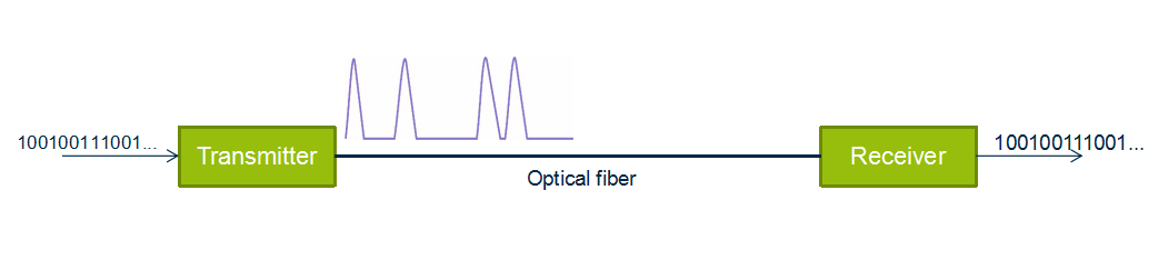
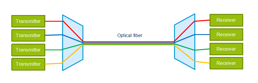
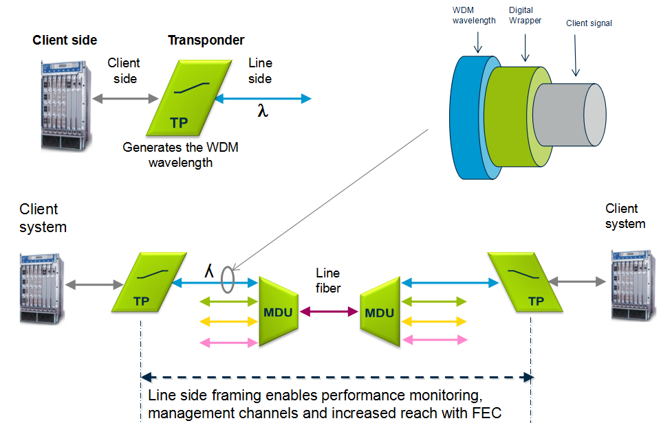
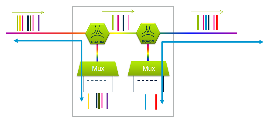
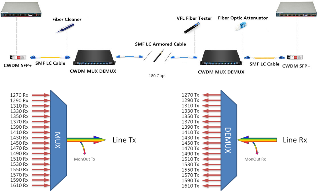
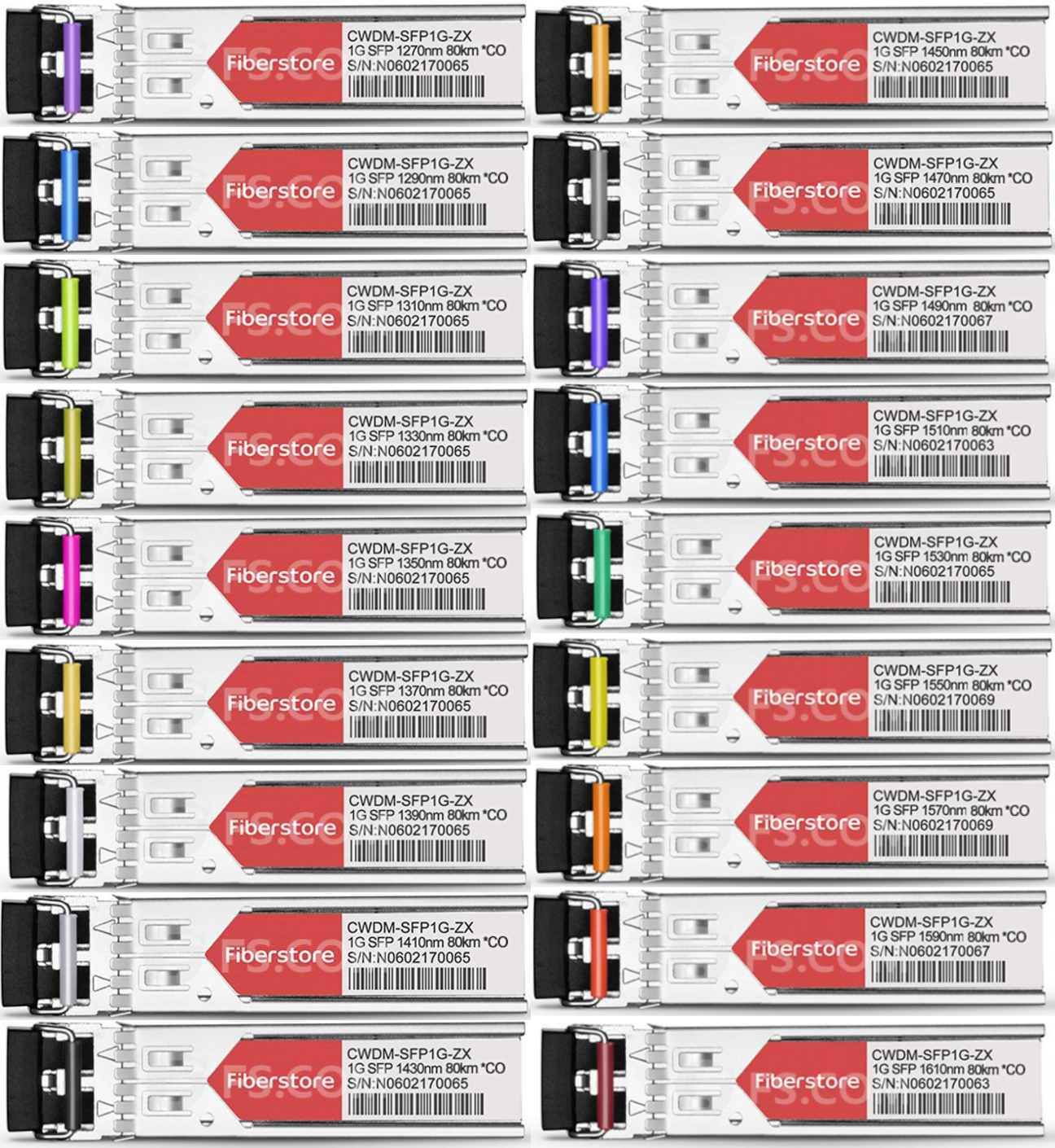
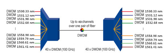
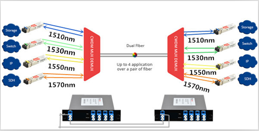
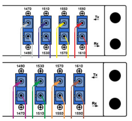
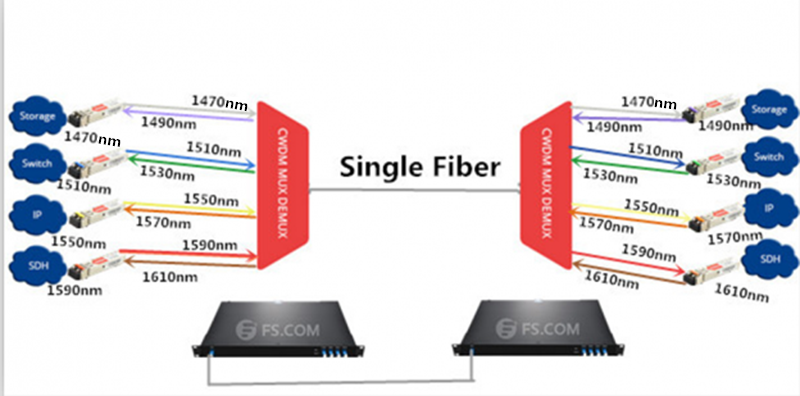
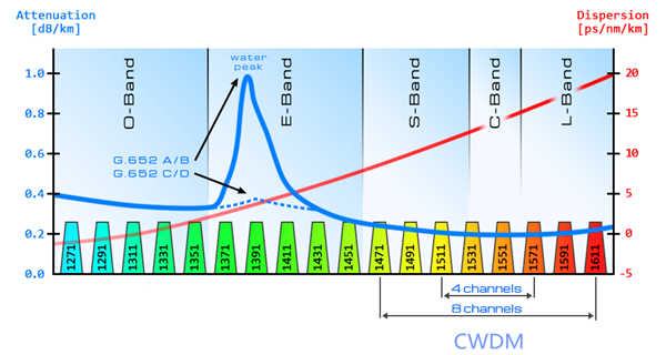
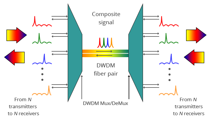
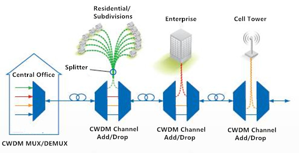
CWDM configuration is usually based on a single-fiber pair: one fiber is for transmitting and the other for receiving. The following figure shows the most basic configuration of optical network with 4 channel CWDM MUX/DEMUX: it often delivers eight wavelengths, from 1471 nm to 1611 nm, with 20 nm apart. A CWDM architecture is quite simple. It only has passive components like multiplexers and demultiplexers, without any active elements such as amplifiers. However, using CWDM as a means of increasing bandwidth also brings network characterization and deployment challenges, which will be discussed in the following section.

cwdm basic configuration

Challenges and Solutions for CWDM Testing

The challenges of CWDM network testing mainly lie in three phases: construction and installation, system activation and upgrade or troubleshoot. Here we provide solutions for each.

Challenge One: Construction and Installation

During construction and installation process, it is essential to conduct physical-layer tests on the fiber from the head-end to the destination. Single-ended testing with an OTDR is definitively an advantage as it optimizes labor resources. In this case, the objectives are to characterize the entire link (not only the fiber) to include the add-drop multiplexers (OADM) and to guarantee continuity up to the final destination. However, testing at standard OTDR wavelengths, such as 1310 nm and 1550 nm, cannot be done in such conditions as these wavelengths are filtered out at either OADM, never reaching the end destination. Then how to test such a link?

cwdm otdr testing

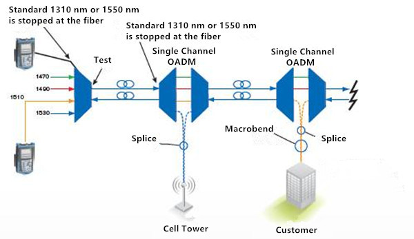
Solution: Adopting a specialized CWDM OTDR. With CWDM-tuned wavelength, the CWDM OTDR is capable of performing an end-to-end test by dropping each test wavelength at the correspondent point on the network, allowing the characterization of each part of the network directly from the head-end. Which is considered time and labor saving since one don’t have to access. It also helps to speed up the deployment process as the technician will test all drop fibers from a single location.

Challenge Two: System Activation

Since CWDM network architecture is rather basic which contains no active components like amplifiers, the only things that can prevent proper transmission in a CWDM network system are transmitter failure, sudden change in the loss created in an OADM or manual errors, bad connections for example. To deal with these problems, one has to look at the signal being transmitted.

Solution: A CWDM channel analyzer is ideal to handle this challenge. It works to quickly determine the presence or absence of each of the 16 wavelengths and their power levels. Many CWDM OADM have tap ports, which means that there is a port where a small portion of the signal is dropped. Taps are typically 20 dB weaker than the main signal. If these taps are not present, a CWDM analysis should be performed. It consists of unplugging the end user to use the main feed for the analysis. To be ready for all possibilities, a CWDM channel analyzer should cover a power range going as low as –40 dBm, while being able to test the entire wavelength range in the shortest time as possible.

Challenge Three: Upgrade or Troubleshoot

In the maintenance and troubleshoot phrase, when the network is live and a new wavelength is added, one should figure out two questions: is the link properly set up? And is my wavelength presents and well?

out-of-band testing of cwdm

Solution: Two approaches are available to check if a link is set up properly: a CWDM OTDR approach or an out-of-band approach. The CWDM OTDR approach is relatively simple when a new customer is added. With CWDM OTDR, one can perform CWDM network testing without having to wait for the customer or to go to the cell tower sites. The wavelength can be turned on at the head-end. Which speed testing process greatly.

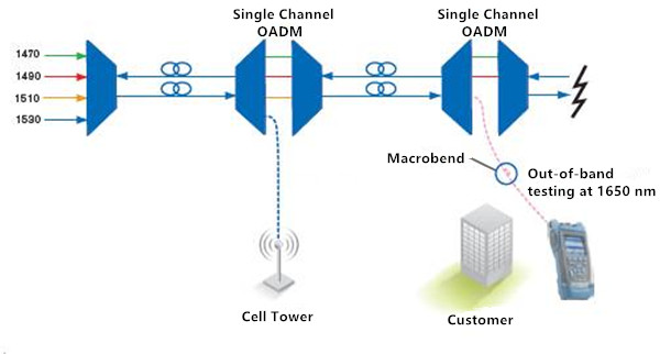
The OTDR and channel analyzer combo are also useful when a single customer has issues. The channel analyzer will reveal if the channel is indeed present and within power budget. If not, the CWDM OTDR can be used to test at that specific wavelength or an out-of-band 1650 nm OTDR test can be performed from the customer’s site to detect any anomalies on the link, all without disconnecting the head-end since the OADM will filter out the 1650 nm, therefore not affecting the remainder of the network.

Conclusion

CWDM testing challenges may be inevitable during each phase of the deployment, but with specialized equipment, these challenges can be overcomed completely. Tools including a CWDM OTDR, a CWDM channel analyzer and an out-of band OTDR are proved effective and valuable to reduce downtime and increase bandwidth at a minimum cost.

5 Concepts Help Easily Get WDM System

Share

The Wavelength Division Multiplexing (WDM) system is a passive, optical solution for increasing the flexibility and capacity of existing fiber lines in high-speed networks. By adding more channels onto available fibers, the WDM System enables greater versatility for data communications in ring, point-to-point, and multi-point topologies for both enterprise and metro applications. Do you know about WDM system? 5 concepts provided in this blog may help you easily get it.

Optical Transmission
Optical transmission is the conversion of a digital stream of information to light pulses. The light pulses are generated by a laser source (LED or vessel) and transmitted over an optical fiber. The receiver converts the light pulses back to digital information.

Optical Transmission

Wavelength Division Multiplexing
WDM is based on the fact that optical fibers can carry more than one wavelength at the same time. The lasers are transmitting the light pulses at different wavelengths that are combined via filters to one single output fiber. The device used to combine wavelengths is called multiplexer and the device used to separate wavelengths is called demultiplexer, which are the two most basic component in WDM system.

Wavelength Division Multiplexing

Optical Amplifiers
An optical amplifier is a device that amplifies an optical signal directly, without the need to first convert it to an electrical signal. Optical amplifiers boosts the attenuated wavelengths and are more cost efficient than electrical repeaters. Without amplifiers the reach is limited to 80-100km before electrical regeneration. Amplifier stations typically each 80-100km.

optical-amplifiers
Depending on signal types and fiber characteristics, amplifiers are used in DWDM networks and increases the reach of the optical signals up to 3000 km. Amplifiers are an basic building block for a powerful DWDM network.

Optical Amplifiers

Transponder
Transponders provides wavelength conversion from client to WDM signal. A transponder maps a single client to a single WDM wavelength. The digital framing of a line signal from a transponder provides service monitoring, management connectivity and increased reach. The broad range of available transponders enables cost efficient solutions for both CWDM & DWDM.

transponder

Optical Add Drop Multiplexer
The main function of an optical multiplexer is to couple two or more wavelengths into the same fiber. If a demultiplexer is placed and properly aligned back-to-back with a multiplexer, it is clear that in the area between them, two individual wavelengths exist. This presents an opportunity for an enhanced function, one in which individual wavelengths could be removed and also inserted. Such a function would be called an Optical Add Drop Multiplexer (OADM). OADM is used for increased flexibility in the optical paths. Services can be redirected upon failure or capacity constraints and capacity can be increased dynamically per node.

optical-add-drop-multiplexer

Conclusion
Multiplexer and demultiplexer are the most basic component in WDM system. If your transmission distance is more than 100 km, an optical amplifier is necessary. If your client wavelength isn’t available for WDM applications, you may need a transponder to convert it to WDM available wavelength. Want to achieve a more flexible, just choose to use a OADM. Besides these, sometimes, a dispersion compensation module is also needed to fix the form of optical signals that are deformed by chromatic dispersion and compensates for chromatic dispersion in fiber that causes the light pulses to spread and generate signal impairment. Do you get WDM system? Just start to build your own WDM system now!

Full CWDM Mux Demux and CWDM SFP Transceivers Solutions

Share

CWDM systems have channels at wavelengths spaced 20 nanometers (nm) apart, compared with 0.4 nm spacing for DWDM. This allows the use of low-cost, uncooled lasers for CWDM. In a typical CWDM system, laser emissions occur on full eighteen channels at eighteen defined wavelengths: 1610 nm, 1590 nm, 1570 nm, 1550 nm, 1530 nm, 1510 nm, 1490 nm, 1470 nm, 1450 nm, 1430 nm, 1410 nm, 1390 nm, 1370 nm, 1350 nm, 1330 nm, 1310 nm, 1290 nm, 1270 nm. Besides, for CWDM systems an industry standard color coding scheme is used. The latches of the CWDM SFP transceivers match the colored port indicators on the passive units therefore guaranteeing simple setup. Following color codes and wavelength are valid for CWDM.

cwdm-channels

Full CWDM Channels (18 Channels) Mux Demux Solution

The WDM system uses a multiplexer at the transmitter to combine several wavelengths together, each one carry different signal with bite-rate up to 10G and a demultiplexer at the receiver to split them apart. Both mux and demux are passive, requiring no power supply. The 18 Channels CWDM mux demux covers all channels of 1270nm to 1610nm in 20nm increments. Without replacing any infrastructure, it totally support data rates up to 180 Gbps by being completely protocol transparent. The main fields of applications are the use in SDH (STM-1, STM-4, STM-16, STM- 64), IP (Fast Ethernet, Gigabit Ethernet, 10 Gigabit) ATM and storage (1G, 2G, 4G, 8G, 10G Fibre Channel) networks. Connectors, located on the front of the CWDM mux demux modules, are labeled and use the same color-coding that is used to indicate the wavelength of the individual CWDM SFP transceivers (shown in the figure below).

cwdm-mux-demux

When fiber availability is limited, CWDM mux demux could increase the bandwidth on the existing fiber infrastructure. By using 18ch CWDM mux demux mentioned above and the CWDM SFP transceivers, up to 180 Gbps could be supported on a fiber pair.

18-channels-cwdm-mux-demux

Full CWDM SFP Transceivers Solution

CWDM SFP transceiver is based on the SFP form factor which is a MSA standard build. The max speed of this product is 1.25G and they are also available as 2.5G and of course the popular CWDM 10G SFP transceivers. The CWDM SFP transceiver has a specific laser which emits a “color” defined in the CWDM ITU grid. The CWDM ITU grid is defined from 1270 to 1610nm and has steps of 20nm. So the available wavelength is 1270nm, 1290nm, 1310nm, 1330nm, 1350nm, 1370nm, 1390nm, 1410nm, 1430nm, 1450nm, 1470nm, 1490nm, 1510nm, 1530nm, 1550nm, 1570nm, 1590nm and C. Besides, our CWDM SFP transceivers are similarly color-coded as the CWDM mux demux to help you match the right link connection (shown in the figure below).

CWDM SFP

We can make the CWDM SFP transceivers compatible with every brand (Cisco, HP, H3C, Juniper, Huawei, Brocade, Arista). A lot of brands have vendor locking and only with the proper coding. Fiberstore is specialized in this rebranding or recoding. We have many different switches and routers in our test lab to test the coding. We also use different Optical Spectrum Analyzers to ensure the CWDM SFP transceiver is emitting the right color and has the correct power budget. The CWDM SFP transceiver is used in combination with passive CWDM mux demux, and we can provide you a complete solution and advice on which equipment fits best in your project. Please give us your project details and we will provide the most efficient and economical solution.

1270nm SFP 1290nm SFP 1310nm SFP 1330nm SFP 1350nm SFP 1370nm SFP
1390nm SFP 1410nm SFP 1430nm SFP 1450nm SFP 1470nm SFP 1490nm SFP
1510nm SFP 1530nm SFP 1550nm SFP 1570nm SFP 1590nm SFP 1610nm SFP

Use Cisco DWDM SFP+ to Connect DWDM Transport to Your Cisco 10G Switches

Share

Dense Wavelength Division Multiplexing (DWDM) enables carrier’s networks to accommodate many hundreds of aggregated services of any sub-rate protocol without installing additional dark fiber. DWDM SFP+ transceiver is mainly manufactured for carriers and large enterprises that need a scalable, flexible, cost-effective system for multiplexing, transporting and protecting high-speed data, storage, voice and video applications. The Cisco DWDM SFP+ transceiver modules are fiber line cards for a wide variety of Cisco switches, routers, and other equipment. They allow enterprises and service providers to provide scalable and easy-to-deploy 10-Gbps LAN, WAN, and optical transport network (OTN) services in their networks.

Cisco DWDM SFP+ Transceiver Channels

According to DWDM ITU (ITU-T G.694.1) channels, Cisco DWDM SFP+ transceivers are provided with 40 channels, from C20 1561.41nm to C59 1530.33nm (shown in the table below).

PN. ITU Channel PN. ITU Channel PN. ITU Channel
DWDM-SFP10G-61.41 C20 1561.41 nm DWDM-SFP10G-50.12 C34 1550.12 nm DWDM-SFP10G-38.98 C48 1538.98 nm
DWDM-SFP10G-60.61 C21 1560.61 nm DWDM-SFP10G-49.32 C35 1549.32 nm DWDM-SFP10G-38.19 C49 1538.19 nm
DWDM-SFP10G-59.79 C22 1559.79 nm DWDM-SFP10G-48.51 C36 1548.51 nm DWDM-SFP10G-37.40 C50 1537.40 nm
DWDM-SFP10G-58.98 C23 1558.98 nm DWDM-SFP10G-47.72 C37 1547.72 nm DWDM-SFP10G-36.61 C51 1536.61 nm
DWDM-SFP10G-58.17 C24 1558.17 nm DWDM-SFP10G-46.92 C38 1546.92 nm DWDM-SFP10G-35.82 C52 1535.82 nm
DWDM-SFP10G-57.36 C25 1557.36 nm DWDM-SFP10G-46.12 C391546.12 nm DWDM-SFP10G-35.04 C53 1535.04 nm
DWDM-SFP10G-56.55 C26 1556.55 nm DWDM-SFP10G-45.32 C40 1545.32 nm DWDM-SFP10G-34.25 C54 1534.25 nm
DWDM-SFP10G-55.75 C27 1555.75 nm DWDM-SFP10G-44.53 C41 1544.53 nm DWDM-SFP10G-33.47 C55 1533.47 nm
DWDM-SFP10G-54.94 C28 1554.94 nm DWDM-SFP10G-43.73 C42 1543.73 nm DWDM-SFP10G-32.68 C56 1532.68 nm
DWDM-SFP10G-54.13 C29 1554.13 nm DWDM-SFP10G-42.94 C43 1542.94 nm DWDM-SFP10G-31.90 C57 1531.90 nm
DWDM-SFP10G-53.33 C30 1553.33 nm DWDM-SFP10G-42.14 C44 1542.14 nm DWDM-SFP10G-31.12 C58 1531.12 nm
DWDM-SFP10G-52.52 C31 1552.52 nm DWDM-SFP10G-41.35 C45 1541.35 nm DWDM-SFP10G-30.33 C59 1530.33 nm
DWDM-SFP10G-51.72 C32 1551.72 nm DWDM-SFP10G-40.56 C46 1540.56 nm
DWDM-SFP10G-50.92 C33 1550.92 nm DWDM-SFP10G-39.77 C47 1539.77nm

Cisco Switches Support for Cisco DWDM SFP+

In fact, not all Cisco switches can be supported for DWDM SFP+ transceivers. According to Cisco 10-Gigabit Ethernet Transceiver Modules Compatibility Matrix, there are 72 types of Cisco switches are available to support DWDM SFP+ transceivers. But only 19 of them can support be supported all 40 channels DWDM SFP+ transceivers (shown in the table below).

Switches Series Models
Cisco Nexus 3000 Series N3K-C3016Q-40GE, N3K-C3064PQ-10GE, N3K-C3064TQ-10GT, N3K-C3064PQ-10GX
Cisco Nexus 3100 Series N3K-C3132Q-40GE, N3K-C3132Q-40GX, N3K-C3132Q-XL, N3K-C3132Q-V, N3K-C3172PQ-10GE, N3K-C3172TQ-10GT, N3K-C3172PQ-XL, N3K-C3172PQ-XL, N3K-C3172TQ-XL, N3K-C31108PC-V, N3K-C31108PC-V
N3K-C31108TC-V, N3K-C31128PQ-10GE
Cisco Nexus 3200 Series N3K-C3264Q, N3K-C3232C
Cisco Nexus 3500 Series N3K-C3548P-10G , N3K-C3524P-10G, N3K-C3548P-10GX, N3K-C3524P-10GX

To build a complete DWDM network in your system, except for switches and DWDM SFP+ transceivers, you also usually need a DWDM mux/demux module. At present, DWDM mux/demux modules are available in 2 channels to 96 channels. Since Cisco DWDM SFP+ transceivers are available in 40 channels (from C20 1561.41nm to C59 1530.33nm ), now I will take 40 channels C20-C59 DWDM mux/demux module (show in the figure below) for example to explain how it works.

40 channels DWDM mux demux

Front panel of above 40 channels C20-C59 DWDM mux/demux module are shown in the figure below. Connectors, located on the front of the DWDM mux/demux modules, are labeled and use the same channel that is used to indicate the wavelength of the individual DWDM transceivers.

DWDM muxdemux
Use a pair of 40 channels C20-C59 DWDM mux/demux modules, 40 signals can be transmitted over one fiber pair, which greatly reduces the cabling cost.

40 DWDM muxdemux
Now, let’s use Cisco compatible DWDM SFP+ to connect DWDM transport to your Cisco 10G SFP+ switches!

Cisco Compatible DWDM SFP+

CWDM Mux/Demux User Guide

Share

When we demand for higher bandwidth, we often choose to install new fiber. However, that is an expensive solution. Then what should we do? Now this article will give you a less expensive solution—using CWDM Mux/Demux with CWDM transceivers, which may allow you to maximize capacity and increase bandwidth on existing fiber route by multiplexing several distinct signals or protocols over a single or duplex-fiber connection. The passive optical CWDM Mux/Demux usually utilizes a thin-film filter and circulator technology. They are available in various wavelength combinations based on the entire wavelength spectrum (1270nm–1610nm in 20nm increments) defined by the ITU G.694.2 CWDM standard. Accordingly, CWDM transceivers are also available in 1270nm–1610nm (20nm spacing).

Since CWDM Mux/Demux can support 18 wavelengths include 1270, 1290, 1310, 1330, 1350, 1370, 1390, 1410, 1430, 1450, 1470, 1490, 1510, 1530, 1550, 1570, 1590 and 1610 nano-meters. Therefore, in the market, the channels of CWDM Mux/Demux varies from 2 channels to 18 channels. In this article, we may introduce these 4 channels CWDM Mux/Demux in detail. Using methods of other channel CWDM Mux/Demux can all reference 4 channels CWDM Mux/Demux.4 channels CWDM Mux/Demux is available in any four wavelengths from 1270nm–1610nm (20nm spacing). At present, CWDM Mux/Demux is available in dual fiber and single fiber two types. In the following passages, I will take 4 channels 1510-1570nm dual fiber CWDM Mux/Demux and 4 channels 1470-1590nm single fiber CWDM Mux/Demux for example to tell you how to use them in your WDM network.

4 Channels 1510-1570nm Dual Fiber CWDM Mux/Demux User Guide
To install a  4 channels 1510-1570nm dual fiber CWDM Mux/Demux in your network, you need a pairs of  4 channels 1510-1570nm dual fiber CWDM Mux/Demux. For dual fiber link  CWDM Mux/Demux, the Mux/Demux are always the same (shown in the following picture).

CWDM Mux/Demux User Guide

Just shown as the following picture. To install a  4 channels 1510-1570nm dual fiber CWDM Mux/Demux in your network, you just need a pair of 4 channels 1510-1570nm dual fiber CWDM Mux/Demux, a 1510nm SFP, 1530nm SFP1550nm SFP and a 1570nm SFP.

4 Channels 1510-1570nm Dual Fiber CWDM MuxDemux

4 Channels 1470-1590nm Single Fiber CWDM Mux/Demux User Guide
To install a  4 channels 1470-1590nm single fiber CWDM Mux/Demux in your network, you also need a pairs of  4 channels single fiber CWDM Mux/Demux. But for single fiber Mux/Demux, they are not the same. If you install a  4 channels 1470-1590nm single fiber CWDM Mux/Demux on one end, you may need to install a 4 channels 1490-1610nm single fiber CWDM Mux/Demux on the other end (shown in the following picture).

CWDM Mux/Demux User Guide

Just shown as the following picture. To install a  4 channels 1470-1590nm single fiber CWDM Mux/Demux in your network, you need a 4 channels 1470-1590nm single fiber CWDM Mux/Demux and 4 channels 1490-1610nm single fiber CWDM Mux/Demux pair. And a 1470nm SFP, 1510nm SFP, 1550nm SFP and 1590nm SFP for 4 channels 1470-1590nm single fiber CWDM Mux/Demux. A 1490nm SFP, 1530nm SFP, 1570nm SFP, 1610nm SFP for  4 channels 1490-1610nm single fiber CWDM Mux/Demux.

Single-Fiber CWDM Mux Demux Application

From O to L: the Evolution of Optical Wavelength Bands

Share

In optical fiber communications system, several transmission bands have been defined and standardized, from the original O-band to the U/XL-band. The E- and U/XL-bands have typically been avoided because they have high transmission loss regions. The E-band represents the water peak region, while the U/XL-band resides at the very end of the transmission window for silica glass.

Optical Wavelength Bands

Intercity and metro ring fiber already carry signals on multiple wavelengths to increase bandwidth. Fibers entering the home will soon do the same. Now there are several types of optical telecom systems have been developed, some based on time division multiplexing (TDM) and others on wavelength division multiplexing (WDM), either dense wavelength division multiplexing (DWDM) or coarse wavelength division multiplexing (CWDM). This article may represent the evolution of optical wavelength bands mainly by describing these three high-performance systems.

Dense Wavelength Division Multiplexing
DWDM systems were developed to deal with the rising bandwidth needs of backbone optical networks. The narrow spacing (usually 0.2 nm) between wavelength bands increases the number of wavelengths and enables data rates of several Terabits per second (Tbps) in a single fiber.

These systems were first developed for laser-light wavelengths in the C-band, and later in the L-band, leveraging the wavelengths with the lowest attenuation rates in glass fiber as well as the possibility of optical amplification. Erbium-doped fiber amplifiers (EDFAs, which work at these wavelengths) are a key enabling technology for these systems. Because WDM systems use many wavelengths at the same time, which may lead to much attenuation. Therefore optical amplification technology is introduced. Raman amplification and erbium-doped fiber amplifiers are two common types used in WDM system.

DWDM

In order to meet the demand for “unlimited bandwidth,” it was believed that DWDM would have to be extended to more bands. In the future, however, the L-band will also prove to be useful. Because EDFAs are less efficient in the L-band, the use of Raman amplification technology will be re-addressed, with related pumping wavelengths close to 1485 nm.

Coarse Wave Division Multiplexing
CWDM is the low-cost version of WDM. Generally these systems are not amplified and therefore have limited range. They typically use less expensive light sources that are not temperaturestabilized. Larger gaps between wavelengths are necessary, usually 20 nm. Of course, this reduces the number of wavelengths that can be used and thus also reduces the total available bandwidth.

CWDM

Current systems use the S-, C- and L-bands because these bands inhabit the natural region for low optical losses in glass fiber. Although extension into the O and E-band (1310 nm to 1450 nm) is possible, system reach (the distance the light can travel in fiber and still provide good signal without amplification) will suffer as a result of losses incurred by use of the 1310 nm region in modern fibers.

Time Division Multiplexing
TDM systems use either one wavelength band or two (with one wavelength band allocated to each direction). TDM solutions are currently in the spotlight with the deployment of fiber-to-the-home (FTTH) technologies. Both EPON and GPON are TDM systems. The standard bandwidth allocation for GPON requires between 1260 and 1360 nm upstream, 1440 to 1500 nm downstream, and 1550 to 1560 nm for cable-TV video.

To meet the rise in bandwidth demand, these systems will require upgrading. Some predict that TDM and CWDM (or even DWDM) will have to coexist in the same installed network fibers. To achieve this, work is underway within the standardization bodies to define filters that block non-GPON wavelengths to currently installed customers. This will require the CWDM portion to use wavelength bands far away from those reserved for GPON. Consequently, they will have to use the L-band or the C- and L-bands and provided video is not used.

tdm

Conclusion
In each case, sufficient performance has been demonstrated to ensure high performance for today’s and tomorrow’s systems. From this article, we know that the original O-band hasn’t satisfied the rapid development of high bandwidth anymore. And the evolution of optical wavelength bands just means more and more bands will be called for. In the future, with the growth of FTTH applications, there is no doubt that C- and L-bands will play more and more important roles in optical transmission system. Fiberstore offer all kinds of products for WDM optical network, such as CWDM/DWDM MUX DEMUX and EDFA. For more information, please visit www.fs.com.

Erbium Doped Fiber Amplifier (EDFA) Used in WDM System

Share

The capacity of fiber optical communication systems has undergone enormous growth during the last few years in response to huge capacity demand for data transmission. With the available wavelength division multiplexing (WDM) equipment, commercial system can transport more than 100 channels over a single fiber. However, increasing the number of channels in such systems will eventually result in the usage of optical signal demultiplexing components with greater values of optical attenuation. Besides, when transmitted over long distances, the optical signal is highly attenuated. Therefore, to restore the optical power budget, it is necessary to implement optical signal amplification. This article may mainly tell you  why EDFA is used in WDM system and how does it work.

Why Use EDFA in WDM System?

EDFA stands for erbium-doped fiber amplifiers, which is an optical amplifier that uses a doped optical fiber as a gain medium to amplify an optical signal. EDFA has large gain bandwidth, which is typically tens of nanometers and thus actually it is enough to amplify data channels with the highest data rates. A single EDFA may be used for simultaneously amplifying many data channels at different wavelengths within the gain region. Before such fiber amplifiers were available, there was no practical method for amplifying all channels between long fiber spans of a fiber-optic link. There are practically two wavelength widows C-Band (1530nm-1560nm) and L-Band (1560nm-1600nm). EDFA can amplify a wide wavelength range (1500nm-1600nm) simultaneously, which just satisfies the DWDM application, hence it is very useful in WDM for amplification.

How Does EDFA Work ?

The basic configuration for incorporating the EDFA in an optical fiber link is shown in the picture below. The signals and pump are combined through a WDM coupler and launched into an erbium-doped fiber (EDF). The amplified output signals can be transmitted through 60-100km before further amplification is required.

EDFA
Erbium-doped fiber is the core technology of EDFA, which is a conventional silica fiber doped with erbium ions as the gain medium. Erbium ions (Er3+) are having the optical fluorescent properties that are suitable for the optical amplification. When an optical signal such as 1550nm wavelength signal enters the EDFA from input, the signal is combined with a 980nm or 1480nm pump laser through a wavelength division multiplexer device. The input signal and pump laser signal pass through erbium-doped fiber. Here the 1550nm signal is amplified through interaction with doped erbium ions. This can be well understood by the energy level diagram of Er3+ ions given in the following figure.

EDFA

Where to Buy EDFA for Your WDM System ?

To ensure the required level of amplification over the frequency band used for transmission, it is highly important to choose the optimal configuration of the EDFAs. Before you buy a EDFA, keep in mind that the flatness and the level of the obtained amplification, and the amount of EDFA produced noise are highly dependent on each of the many parameters of the amplifier. Fiberstore provide many kinds of EDFAs, especially the DWDM EDFAs (shown in the picture below), which have many output options (12dBm-35dBm). Besides, they are very professional in optical amplifiers. Whatever doubts you have, they can give a clear reply.

EDFA

Capacity Expansion and Flexibility—DWDM Network

Share

DWDM increases the bandwidth of an optical fiber by multiplexing several wavelengths onto it. Even though it costs more than CWDM, it is currently the most popular WDM technology because it offers the most capacity. This article provides an overview of DWDM networks and its current applications.

Introduction of DWDM Technology
Dense wavelength-division multiplexing (DWDM) revolutionized data transmission technology by increasing the capacity signal of embedded fiber. This increase means that the incoming optical signals are assigned to specific wavelengths within a designated frequency band, then multiplexed onto one fiber. By providing channel spacings of 50 GHz (0.4 nm), 100 GHz (0.8 nm) or 200 GHz (1.6 nm), several hundreds of wavelengths can be placed on a single fiber. DWDM takes advantage of the operating window of the Erbium Doped Fibre Amplifier (EDFA) to amplify the optical channels and extend the operating range of the system to over 1500 kilometers. The following picture shows the operation of a DWDM system.

Bi-Directional-DWDM-Operation

Components of DWDM System
Important components for DWDM systems are transmitters, receivers, optical amplifiers, transponders, DWDM multiplexers, and DWDM demultiplexer. These components, along with conforming to ITU channel standards, allow a DWDM system to interface with other equipment and to implement optical solutions throughout the network.

  • Optical transmitters/receivers

Transmitters are described as DWDM components since they provide the source signals which are then multiplexed. The characteristics of optical transmitters used in DWDM systems are highly important to system design. Multiple optical transmitters are used as the light sources in a DWDM system. Here we can ues a transceiver to replace transmitters and receivers, since it is the combiantion of them. Transceivers applied in DWDM network are often called the DWDM transceiver, of which the transmission distances can reach up to 120 km. The following picture shows the receivers and transmitters in DWDM systems.

Optical transmitters/receivers

  • Optical amplifiers

Optical amplifiers (OAs) boost the amplitude or add gain to optical signals passing on a fiber by directly stimulating the photons of the signal with extra energy. They are “in-fiber” devices. OAs amplify optical signals across a broad range of wavelengths. This is very important for DWDM system application. Erbium-doped fiber amplifiers (EDFAs) are the most commonly used type of in-fiber optical fibre. Following picture shows the operation of OA.

Optical amplifiers

  • Transponders

Transponders convert optical signals from one incoming wavelength to another outgoing wavelength suitable for DWDM applications. Transponders are optical-electricaloptical (O-E-O) wavelength converters. A transponder performs an O-E-O operation to convert wavelengths of light. Within the DWDM system a transponder converts the client optical signal back to an electrical signal (O-E) and then performs either 2R (reamplify, reshape) or 3R (reamplify, reshape, and retime) functions. The following picture shows the operation of bidirectional transponder.

Transponders

A transponder is located between a client device and a DWDM system. From left to right, the transponder receives an optical bit stream operating at one particular wavelength (1310 nm). The transponder converts the operating wavelength of the incoming bitstream to an ITU-compliant wavelength. It transmits its output into a DWDM system. On the receive side (right to left), the process is reversed. The transponder receives an ITU-compliant bit stream and converts the signals back to the wavelength used by the client device.

  • DWDM Multiplexers and Demultiplexers

Multiple wavelengths (all within the 1550 nm band) created by multiple transmitters and operating on different fibers are combined onto one fiber by way of an optical multiplexer. The output signal of an optical multiplexer is referred to as a composite signal. At the receiving end, a demultiplexer separates all of the individual wavelengths of the composite signal out to individual fibers. The individual fibers pass the demultiplexed wavelengths to as many optical receivers. Typically, mux and demux (transmit and receive) components are contained in a single enclosure. Optical mux/demux devices can be passive. Component signals are multiplexed and demultiplexed optically, not electronically, therefore no external power source is required. Following picture shows the operation of DWDM multiplexers and demultiplexers.

DWDM Multiplex and Demultiplex

Applications for DWDM
As occurs with many new technologies, the potential ways in which DWDM can be used are only beginning to be explored. Already, however, the technology has proven to be particularly well suited for several vital applications.

  • DWDM is ready made for long-distance telecommunications operators that use either point–to–point or ring topologies. The sudden availability of 16 new transmission channels where there used to be one dramatically improves an operator’s ability to expand capacity and simultaneously set aside backup bandwidth without installing new fiber.
  • This large amount of capacity is critical to the development of self-healing rings, which characterize today’s most sophisticated telecom networks. By deploying DWDM terminals, an operator can construct a 100% protected, 40 Gb/s ring, with 16 separate communication signals using only two fibers.
  • Operators that are building or expanding their networks will also find DWDM to be an economical way to incrementally increase capacity, rapidly provision new equipment for needed expansion, and future–proof their infrastructure against unforeseen bandwidth demands.

Ultra-High-Power Optical Amplifier for FTTH – EYDFA

Share

Background

While the Cable Modem, xDSL, and other forms of broadband access are booming in recent years, Fiber To The Home (FTTH) access is also gradually becoming a project that people are very interested in. The FTTH will eventually realize the “three networks in one” of Telephone, CATV and Internet, when the speed of data transmission can be more than 100 Mbps (200 times faster than the commonly used dial-up Internet access) and bring homes high-definition TV movies and fast online office, etc. FTTH can also solve the problem such as the quality of phone calls, the definition of television and so on.

From the perspective of the world’s situation, the FTTH’s promotion of South Korea and Japan has entered a rapid growth period; North America and Europe has begun to start which brings an optimistic outlook; China, Russia, India and South America is following and speeding up the development. From the perspective of FTTH, the optical communications industry market’s growth potential is still very large.

Applications of High-Power Optical Amplifiers

High-power optical amplifier as one of the basic devices of modern optical communications, is not only the premise of the existence of large-capacity and long-distance all-optical communication networks, but also plays a more and more important role in the process of fiber optic networks’ constantly extending and expanding. At present, in the central office, it usually needs to install more than one optical amplifiers in order to cover larger scope and more users. To take CATV for example, if a medium-sized county needs to send high-quality first-level TV signals to the villages and towns, it generally needs 4 to 8 sets of optical amplifiers. However, if high-power optical amplifiers are used, then only one is enough, which can greatly reduce the cost.

Solutions of High-Power Optical Amplifiers

Traditional Solution using EDFA Technology

One of the solutions for high-power optical amplifiers is to use the traditional general EDFA technology. As shown in the figure below, the signal is amplified at the first stage and then divided into several parts into several EDFAs at the second stage to realize the further ascension of power. The power enlarged in the end can be allocated.

Traditional High-Power Solution using EDFAs

Theare are mainly four problems of this solution:

  • The adoption of multilevel structure will make the optical structure very complex, and due to the adoption of multiple lasers in the internal part, the corresponding control scheme is very complicated.
  • As the multilevel structure has a WDM between the two stages of optical amplifiers, equivalent to bring more insertion loss to the optical path, the noise figure of EDFA amplifiers will deteriorate.
  • In addition, the traditional EDFAs use single mode fiber core pump technology, but high-power single-mode pumped lasers have been greatly restricted on technical and cost.
  • The whole sets of EDFA’s cost is very high and is very expensive.

Better Solution using EYDFA Technology

This ultra-high-power amplifier technology is a multimode cladding pump technology—EYDFA technology, a recently developed new technology that uses the Yb3+ and Er3+ ions doped double-clad fiber. The technology results to the combination of a series of new technologies, new processes and new materials. It is the core technology of ultra-high-power amplifiers and represents the development direction of optical amplifier technologies. While traditional EDFA use single-mode fiber core pump technology to achieve higher output power (which has been greatly limited on the technical and cost), the Er/Yb-Doped Fiber Amplifier (EYDFA) multimode cladding pump technology is the best choice for large output power optical amplifiers. Here is a typical optical structure of EYDFA.

EYDFA Structure

The main advantages of EYDFA are as following:

  • Compared with the single mode fiber core pump technology, multimode cladding pump technology has obvious advantages. The multimode cladding pump technology is to input the pump light to the multimode double-cladding fiber whose cross section are hundreds to thousands of times the single-mode fiber. As a result, at the same input optical density, multimode cladding pump can allow hundreds to thousands of times the single-mode pumped input, easily realizing the optical amplifiers’ high output power or ultra-high output power.
  • Can be realized using a simple optical structure, so the application form is very simple (as shown in the figure below).EYDFA Application Structure
  • The overall cost of the pumps can be greatly reduced.

Fiberstore’s high-power optical amplifier module type products—FTTH-EYDFA series are featured with high output power (17–26 dBm), low noise figure (less than 6 dB @ 1550 nm, 5 dBm input power), wide range of working wavelength (1540–1565 nm), flexible control, high reliability, etc. The output power of high-power optical amplifier is nearing 32 dBm in the laboratory.

Conclusion

Predictably, the widely applications of the ultra-high-power optical amplifiers (EYDFA) will have a profound impact on the development of optical communication, and its market prospect and effectiveness to economic and social present a good trend.

Advanced Optical Components – Optical Isolator

Share

Connectors and other types of optical devices on the output of the transmitter may cause reflection, absorption, or scattering of the optical signal. These effects on the light beam may cause light energy to be reflected back at the source and interfere with source operation. To reduce the effects of the interference, an Optical Isolator is used. Many laser-based transmitters and Optical Amplifiers use an optical isolator because the components that make up the optical circuit are not perfect.

The optical isolator comprises elements that will permit only forward transmission of the light; it does not allow for any return beams in the fiber transmission routes or in the optical amplifiers. There are a variety of optical isolator types, such as Polarized (dependent and independent), Composite, and Magnetic.

Polarized Optical Isolator

As mentioned, the Polarized Optical Isolator transmits light in one direction only. This is accomplished by using the polarization axis of the linearly polarized light. The incident light is transformed to linearly polarized light by traveling through the first polarizer. The light then goes through a Faraday rotator; this takes the linearly polarized light and rotates the polarization 45 degrees, then the light passes through the exit polarizer. The exit polarizer is oriented at the same 45 degrees relative to the first polarizer as the Faraday rotator is. With this technique, the light is passed through the second polarizer without any attenuation. This technique allows the light to propagate forward with no changes, but any light traveling backward is extinguished entirely.

The loss of backward-traveling light occurs because when the backward light passes through the second polarizer, it is shifted again by 45 degrees. The light then passes through the rotator and again is rotated by 45 degrees in the same direction as the initial tilt. So when the light reaches the first polarizer, it is polarized at 90 degrees. And when light is polarized by 90 degrees, it will be “shut out.” The figures below show the forward- and reverse-transmitted light in a dependent polarized optical isolator.

Forward-Transmitted Light through a Polarized Optical Isolator

Reverse-Transmitted Light through a Polarized Optical Isolator

It should be noted that these figures depict the dependent type of polarized optical isolator. There is also an independent polarized optical isolator. The independent device allows all polarized light to pass through, not just the light polarized in a specific direction. The principle of operation is roughly the same as the dependent type, just slightly more complicated. Tips: The Independent Optical Isolators are frequently used in EDFA Optical Amplifiers.

Composite Optical Isolator

In fact, Composite Optical Isolator is a type of polarization independent isolator used in the EDFA optical amplifier. The EDFA optical amplifier is comprised of Erbium-Doped Fiber, Wavelength-Division Multiplexer, Pumping Diode Laser, Polarization Independent Isolator, and other passive components. Because the polarization independent isolator is composited with the others components into a single EDFA module, it is called a Composite Optical Isolator.

Magnetic Optical Isolator

Magnetic Optical Isolator is another name for polarized optical isolator. The magnetic portion of any isolator is of great importance. As mentioned, there is a Faraday rotator in the optical isolators. The Faraday rotator is a rod composed of a magnetic crystal having a Faraday effect and operated in a very strong magnetic field. The Faraday rotator ensures that the polarized light is in the correctly polarized plane, thus ensuring that there will be no power loss. Here is a figure that shows a basic magnetic optical isolator.

Magnetic Optical Isolator

Optical isolators are used to ensure stabilization of laser transmitters and optical amplifiers as well as to maintain good transmission performance. Ultra speed and large capacity optical fiber trunk systems are expanding as a result of the development of optical amplifiers. In parallel, the demand for optical isolators is increasing. Demand is also expected to increase as LAN and other subscriber fiber optic networks expand. It is therefore imperative that optical isolators be further improved to achieve higher performance, smaller size, and lower price. Luckily, you can now find the best optical isolators solution in Fiberstore, a Manufacturer & Supplier of Fiber Optic Network Solutions focus on Professional Customization.

Optical Isolator in Standard Size Jacket Tube

Related Article:  Which Patch Cable Should I Choose for My Optical Transceiver?