Category Archives: Passive Optical Network

Copper 10GBASE-T Switch Recommendation

Share

In the past few years, network speeds have increased dramatically as applications like video and technologies like virtualization need higher speed and performance. Therefore, 10 Gigabit Ethernet (10GbE) is widely deployed for inter-switch and server-to-switch links. Generally, there are two 10G switch solutions for the aforesaid 10GbE link: 10GBASE-T switch for copper and 10G SFP+ switch. And since the 10GbE copper switch is more favored by the market, this post will focus on copper10GBASE-T  network switch recommendation.

10GBASE-T Switch vs SFP+ Switch: Why Choose 10GBASE-T Copper Link?

Many people may wonder why 10GBASE-T copper link is more favored by the market. This part will discuss this topic in a brief way.

As we all know, copper 10GBASE-T switch uses copper cables to transmit 10Gbps data. This may help to save much money because copper cable infrastructure is far less expensive than the fiber optics of 10G SFP+ switch. In addition, 10GBASE-T network is easier to be employed and allows users to make the best of their existing Cat6a UTP structured cabling ecosystem. Despite all this, 10G SFP+ link also has such advantages as lower latency and lower power budget. For detailed information, you may read 10GBASE-T VS SFP+: Which to Choose for 10GbE Data Center Cabling.

10GBASE-T Switch Recommendation for Copper

Since 10GBASE-T network is favored by many IT managers, lots of cheap 10GB switch for copper has been supplied in the market. These switches are either 2/4/8/16 port copper switch for home networks or 20+ port 10GBASE-T switch for enterprise and data center networks. This part will introduce a high performance 48 port 10GBASE-T copper switch with 40Gbe QSFP+ UpLink – S5850-48T4Q – for your reference.
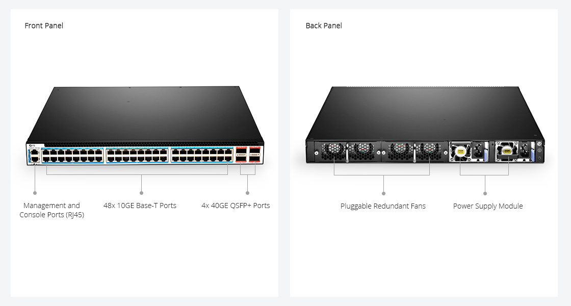
Copper 10GBASE-T Switch

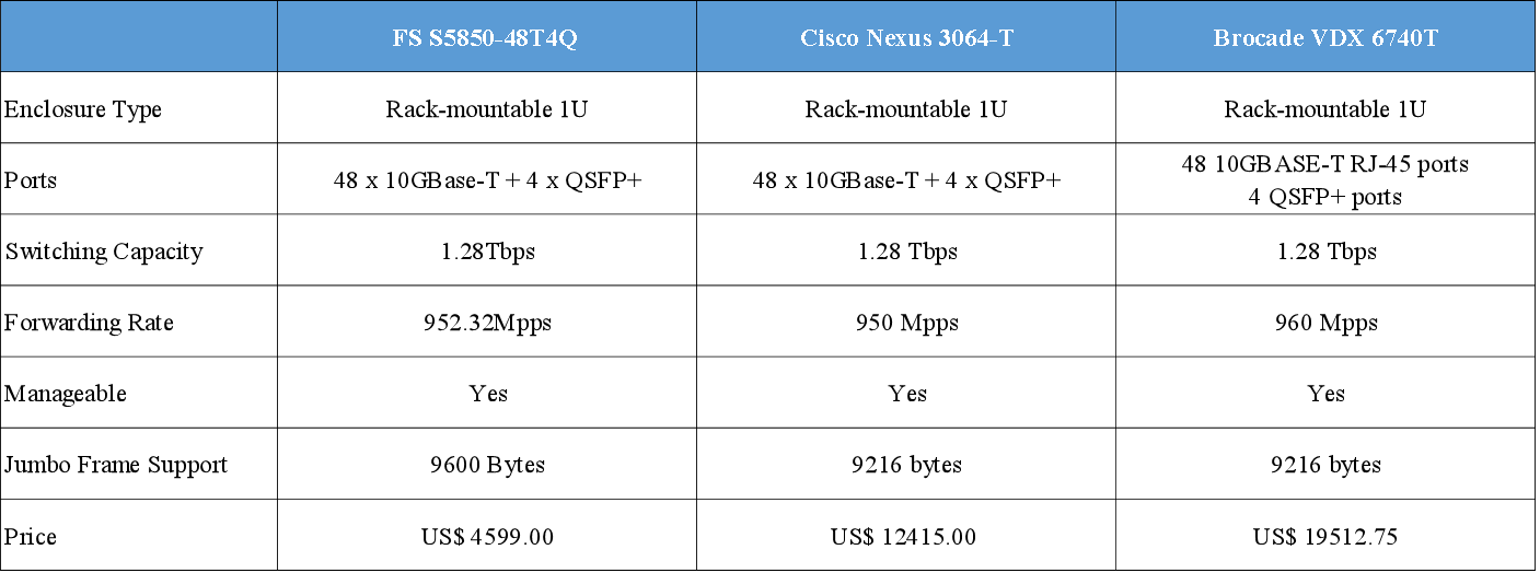
S5850-48T4Q is a 1U managed L2/L3 Ethernet switch. It is designed to meet next generation Metro, Data Center and Enterprise network requirements. Featuring 48 10GBASE-T RJ-45 ports and 4 40G QSFP+ ports, it can provide 1.28Tbps switching capacity. And it has a forwarding rate of 952.32Mpps. The following table compares the key parameters and prices of S5850-48T4Q and other similar switches:

48 port 10GBASE-T Copper Switches

Seen from the above table, you may find that the ports and performance of the three copper 10GBASE-T switches are nearly the same, but Cisco Nexus 3064-T and Brocade VDX 6740T switches are much more expensive than the S5850-48T4Q. This is because their prices include both the actual value of the switch and their specific brands which are always costly. And their after-sale services may be better than most small companies. However, this FS S5850-48T4Q switch is also guaranteed with free tech support and back up support.

S5850-48T4Q 10GBASE-T Switch for Spine-Leaf Application

Unlike most copper 10GBASE-T switches, S5850-48T4Q can be used for Spine-Leaf network which is a popular architecture design for data center. To be specific, S5850-48T4Q is often used as the leaf switch in a 40G Spine-Leaf design. As shown below, the 4OG QSFP+ ports of S5850-48T4Q often used to connect to the spine switch (S8050-20Q4C). And the 10GBASE-T copper ports are connect to servers and routers. Read more about Building Spine-Leaf Network with 10GBASE-T Switch

ToR

Conclusion

For lower cost and ease of use, copper 10GBASE-T switch is popular among 10Gb switches. If you plan to migrate to 10GbE network, 10GBASE-T copper network is a good choice. It will help to reduce the cost complexity and cabling issues around the migration to 10GbE in the data center.

Related Article:

Unique Advantages of 10GBASE-T in Migrating Data Center to 10Gb

FS 10GBASE-T Switch: Breaks the Price Barrier for 10G Network 


The Latest Generation of PON – NG-PON2

Share

To meet the large demand for high capacity transmission in optical access systems, 10G-PON (10G Passive Optical Network) has already been standardized by IEEE (Institute of Electrical and Electronics Engineers) and ITU (International Telecommunication Union). To enable the development of future optical access systems, the most recent version of PON known as NG-PON2 (Next-Generation Passive Optical Network 2) was approved recently, which provides a total throughput of 40 Gbps downstream and 10 Gbps upstream over a single fiber distributed to connected premises. The migration from GPON to 10G-PON and NG-PON2 is the maturity of technology and the need for higher bandwidth. This article will introduce the NG-PON2 technology to you.

GPON 10G-PON NG-PON2

What Is NG-PON2?
NG-PON2 is a 2015 telecommunications network standard for PON which was developed by ITU. NG-PON2 offers a fiber capacity of 40 Gbps by exploiting multiple wavelengths at dense wavelength division multiplexing (DWDM) channel spacing and tunable transceiver technology in the subscriber terminals (ONUs). Wavelength allocations include 1524 nm to 1544 nm in the upstream direction and 1596 nm to 1602 nm in the downstream direction. NG-PON2 was designed to coexist with previous architectures to ease deployment into existing optical distribution networks. Wavelengths were specifically chosen to avoid interference with GPON, 10G-PON, RF Video, and OTDR measurements, and thus NG-PON2 provides spectral flexibility to occupy reserved wavelengths in deployments devoid of legacy architectures.

How Does NG-PON2 Work?
If 24 premises are connected to a PON and the available throughput is equally shared then for GPON each connection receives 100 Mbps downstream and 40 Mbps upstream over a maximum of 20 km of fiber. For 10G-PON, which was the second PON revision, each of the 24 connections would receive about 400 Mbps downstream and 100 Mbps upstream. The recently approved NG-PON2 will provide a total throughput of 40 Gbps downstream and 10 Gbps upstream over a maximum of 40 km of fiber so each of the 24 connections would receive about 1.6 Gbps downstream and 410 Mbps upstream. NG-PON2 provides a greater range of connection speed options including 10/2.5 Gbps, 10/10 Gbps and 2.5/2.5 Gbps. NG-PON2 also includes backwards compatibility with GPON and 10G-PON to ensure that customers can upgrade when they’re ready.

NG-PON2 Work Principle

NG-PON2 Advantages
The NG-PON2 technology is expected to be about 60 to 80 percent cheaper to operate than a copper based access network and provides a clear undeniable performance, capacity and price advantage over any of the copper based access networks such as Fiber to the Node (FTTN) or Hybrid Fiber Coax (HFC). At present, three clear benefits of NG-PON2 have been proved. They are a 30 to 40 percent reduction in equipment and operating costs, improved connection speeds and symmetrical upstream and downstream capacity.

Reduced Costs
NG-PON2 can coexist with existing GPON and 10G-PON systems and is able to use existing PON-capable outside plant. Since the cost of PON FTTH (Fiber to the Home) roll out is 70 percent accounted for by the optical distribution network (ODN), this is significant. Operators have a clear upgrade path from where they are now, until well into the future.

Improved Connection Speeds
Initially NG-PON2 will provide a minimum of 40 Gbps downstream capacity, produced by four 10 Gbps signals on different wavelengths in the O-band multiplexed together in the central office with a 10 Gbps total upstream capacity. This capability can be doubled to provide 80 Gbps downstream and 20 Gbps upstream in the “extended” NG-PON2.

Symmetrical Upstream and Downstream Capacity
Both the basic and extended implementations are designed to appeal to domestic consumers where gigabit downstream speeds may be needed but more modest upstream needs prevail. For business users with data mirroring and similar requirements, a symmetric implementation will be provided giving 40/40 and 80/80 Gbps capacity respectively.

With the introduction of NG-PON2, there is now an obvious difference between optical access network and copper access network capabilities. Investment in NG-PON2 provides a far cheaper network to operate, significantly faster downstream and upstream speeds and a future-proof upgrade path all of which copper access networks do not provide, thus making them obsolete technologies. Telephone companies around the world have been carrying out trials of NG-PON2 and key telecommunication vendors have rushed NG-PON2 products to market.

Source: http://www.fs.com/blog/the-latest-generation-of-pon-ng-pon2.html

Wavelength Selective Couplers and Splitters

Share

Wavelength Selective Couplers (or Splitters) are used to either combine or split light of different wavelengths with minimal loss. Light of two different wavelengths on different input fibers can be merged (combined) onto the same output fiber. In the reverse direction light of two different wavelengths on the same fiber can be split so that one wavelength goes to one output fiber and the other wavelength is output onto the other output fiber. The process can be performed with very little loss.

As the coupling length is wavelength dependent, the shifting of power between the two parallel waveguides will take place at different places along the coupler for different wavelengths. All we need to do is choose the coupling length carefully and we can arrange for loss free wavelength combining or splitting. These functions are shown in the figure below. The graph of power transfer shows how power input on one of the fibers shifts back and forth between the two waveguides. The period of the shift is different for the two different wavelengths. Thus in the left-hand section of the diagram (combining wavelengths) there will be a place down the coupler where all of the light is in only one waveguide. If we make the coupler exactly this length then the signals have been combined. On the right-hand side of the diagram the reverse process is shown where two different wavelengths arrive on the same input fiber. At a particular point down the coupler the wavelengths will be in different waveguides so if we make this the coupling length then we have separated the wavelengths exactly. In fact both the processes described above are performed in the same coupler—the process is Bi-Directional (BiDi). Thus the coupler on the left can operate in the opposite direction and become a splitter and the splitter on the right can operate in the opposite direction and become a coupler (combiner). Note that each coupler or splitter must be designed for the particular wavelengths to be used.

Wavelength Selective Coupling and Splitting

Commercial devices of this kind are commonly available and are very efficient. The quoted insertion loss is usually between 1.2 and 1.5 dB and the channel separation is quoted as better than 40 dB. “Wavelength flattened” couplers or splitters of this kind operate over quite a wide band of wavelengths. That is a given device may allow input over a range of wavelengths in the 1310 nm band up to 50 nm wide and a range of wavelengths in the 1550 nm band also up to 50 nm wide.

Power Input to an EDFA

On the left-hand side of the figure we see an example of coupling two different wavelengths into the same output fiber. At the input of an EDFA you want to mix the (low level) incoming signal light with (high level) light from the pump. Typically the signal light will be around 1550 nm and the pump will be 980 nm. In this case it is possible to choose a coupling length such that 100% of the signal light and 100% of the pump light leaves on the same fiber. A major advantage of this is that there is very little loss of signal power in this process.

Splitting Wavelengths for CWDM Systems

On the right-hand side of the figure we show an example of CWDM demultiplexing. A mixed wavelength stream with one signal in each of the 1300 and 1550 nm bands is separated into its two component wavelengths. A CWDM system like this might be used in a system for distributing CATV and advanced VOD services to people in their homes. One signal stream might be carried at 1310 nm and the other at 1550 nm. A resonant coupler is shown here operating as a splitter separating the two wavelengths. Note that an identical splitter could also be used to combine the two wavelengths with very little loss.

Adding the Management Channel in DWDM Systems

In DWDM systems where many channels are carried in the 1550 nm band there is often a requirement to carry an additional relatively slow rate channel for management purposes. A convenient way to do this is to send the management information in the 1310 nm band and the mixed DWDM stream in the 1550 band. Wavelength selective couplers are commonly used for this purpose. A management signal (a single wavelength) in the 1310 band is coupled onto a fiber carrying many wavelengths between 1540 nm and 1560 nm. Another similar device (wavelength selective splitter) is used to separate the signals at the other end of the link.

Article Source: http://www.fiberopticshare.com/wavelength-selective-couplers-and-splitters.html

The Basic Parameters of Passive Optical Network Devices

Share

There are many devices elementary but necessary for the Passive Optical Network (PON) applications that require the transmission, combining, or distribution of optical signals. These passive devices include the Optical Splitter/Coupler, Optical Switch, Optical Attenuator, Optical Isolator, Optical Amplifier, and WDM Filters (CWDM/DWDM Multiplexer) etc. Tips: The passive devices are components that do not require an external energy source.

When working with these passive devices it is important to have a basic understanding of common parameters. Some of the basic parameters that apply to each device are Optical Fiber Type, Connector Type, Center Wavelength, Bandwidth, Insertion Loss (IL), Excess Loss (EL), Polarization-Dependent Loss (PDL), Return Loss (RL), CrossTalk (XT), Uniformity, Power Handling, and Operating Temperature.

Connector Type and Optical Fiber Type

Many passive devices are available with receptacles or fiber optic pigtails. The pigtails may or may not be terminated with a fiber optic connector. If the device is available with a receptacle or connector, the type of receptacle or connector needs to be specified when ordered. You should also note the type of optical fiber used by the manufacturer of the device to ensure it is compatible with the optical fiber used for your application.

Center Wavelength and Bandwidth

Center Wavelength is the nominal operating wavelength of the passive device.

Bandwidth (or bandpass) is the range of wavelengths over which the manufacturer guarantees the performance of the device. Some manufacturers will list an operating wavelength range instead.

Types of Loss

  • IL is the optical power loss caused by the insertion of a component into the fiber optic system. When working with passive devices, you need to be aware of the IL for the device and the IL for an interconnection. IL as stated by the manufacturer typically takes into account all other losses, including EL and PDL. IL is the most useful parameter when designing a system.
  • EL may or may not be defined by the manufacturer. EL associated with fiber optic couplers, is the amount of light lost in the coupler in excess of the light lost from splitting the signal. In other words, when a coupler splits a signal, the sum of the power at the output ports does not equal the power at the input port; some optical energy is lost in the coupler. EL is the amount of optical energy lost in the coupler. This loss is typically measured at the specified center wavelength for the device.
  • PDL is only a concern for Single-Mode passive devices. It is often the smallest value loss, and it varies as the polarization state of the propagating light wave changes. Manufacturers typically provide a range for PDL or define a not-to-exceed number.
  • RL, short for Return Loss or Reflection Loss, is typically described as this: when a passive device is inserted, some of the optical energy from the source is going to be reflected back toward the source. RL is the negative quotient of the power received divided by the power transmitted.

Tips: IL, EL, PDL, RL are all measured in decibels(dB).

CrossTalk (XT)

XT in an optical device describes the amount of light energy that leaks from one optical conductor to another. XT is not a concern in a device where there is a single input and multiple outputs. However, it is a concern with a device that has multiple inputs and a single output, such as an optical switch. XT is also expressed in dB, where the value defines the difference between the optical power of one conductor and the amount of leakage into another conductor. In an optical switch with a minimum XT of 60 dB, there is a 60 dB difference between the optical power of one conductor and the amount of light that leaked from that conductor into another conductor.

Uniformity

Uniformity is a measure of how evenly optical power is distributed within the device, expressed in dB as well as XT. For example, if a device is splitting an optical signal evenly into four outputs, how much those outputs could vary from one another is defined by uniformity. Uniformity is typically defined over the operating wavelength range for the device.

Power Handing

Power Handling describes the maximum optical power at which the device can operate while meeting all the performance specifications defined by the manufacturer. Power handling may be defined in mW(milliwatt) or dB, where 0 dBm is equal to 1 mW.

Operating Temperature

Operating Temperature describes the range of temperatures that the device is designed to operate in. This can vary significantly between devices, because some devices are only intended for indoor applications while others may be used outdoors or in other harsh environments.

Article Source: http://www.fiberopticshare.com/the-basic-parameters-of-passive-optical-network-devices.html

FBG Sensor Multiplexing Techniques On WDM System

Share

Fiber Bragg Grating (FBG) is a simple and low-cost filter built into the core of a wavelength-specific fiber cable. FBGs are used as inline optical filters to block certain wavelengths, or as wavelength-specific reflectors.

In many applications a large number of sensors need to be used to achieve a distributed measurement of the parameters. In particular, using sensors in smart structures is of interest where sensor arrays are bonded or embedded into the materials to monitor the health of the structure. FBG sensors have a distinct advantage over other sensors because they are simple, intrinsic sensing elements that can be written into a fiber, and many sensors can be interrogated through a single fiber.

The most straightforward multiplexing technique for FBG sensors is wavelength division multiplexing (WDM), utilizing the wavelength-encording feature of an FBG-based sensor. The WDM technique is based on spectral splicing of an available source specturm. Each FBG sensor can be encoded with a unique wavelength along a single fiber. Since we are operating in the wavelength domain, the physical spacing between FBG sensors can be as short as desired to give accurate distributed information of measurands.

A parallel topology is used to allow simultaneous interrogation of all the sensors in WDM, as shown in Figure 4.15. A1 x N fiber optic splitter is used to divide the optical reflection into N channels, In each channel a matched fiber grating detects the wavelength shift from a specific FBG sensor.

Fiber splitter

In the parallel scheme each filter receives less than 1/2N of optical power as a result of using 1 x N fiber splitter and fiber coupler. More FBG sensors lead to a larger power penalty. An improved scheme using a serial matched FBG array is reported by Brady et al, as shown in Figure 4.15(b). This scheme is claimed to allow the optical power to be used more efficently than in the parallel topology. As can be seen, however, a large power penalty still exists through the use of the reflection of matched fiber gratings. A revised verison of the serial scheme is proposed, in which the transmisson of the matched FBG is used to monitor the wavelength shift from the corresponding sensing FBG. This reduces the power penalty of 6 dB.

Variable Optical Attenuator Description

Share

High intensity, coherent light beams are used as an increasingly common means of transmitting data. Optical fibers provide higher data rates with lower cost, weight and volume per units of length than cables relying on metallic conductors.

A variety of devices are known for controlling the light beam. Once of these is the fibre attenuator.

An exemplary optical attenuator is described and shown in U.S. NO. 4,192,573 to Brown, Jr.ct al. A flat mirror reflects an input beam of light. A focusing mirror receives the beam of light reflected from the flat mirror, so that the axis of the beam of light reflected by the focusing mirror is offset from and, parallel to, the axis of the input beam of light. A pinhole assembly receives the beam of light reflected from the focusing mirror. The pinhole assembly has a pinhole positioned on the axis of the beam of light reflected by the focusing mirror. A servo-motor actuates the flat mirror and the focusing mirror, in unison, relative to the pinhole assembly in a direction parallel to the axis of the input beam of light. The parallel movement of the mirror acts to vary the proportion of the input beam of light that passes through the pinhole. The servo mechanism is bulky and requires a relatively long period of time to move the mirrors relative to the pinhole assembly.

The present invention is a variable optical attenuator (VOA) which has a semiconductor micro-electro-mechanical device for positioning a reflecting surface in any of a plurality of positions, each providing a respectively different amount of attenuation.

The variable optical attenuator includes a Icns, a first optical waveguide, and a second optical waveguide. A semiconductor micro-electro-mechanical device is positioned on a side of the lens opposite the first and second optical waveguides. The device has a reflecting surface. The reflecting surface has a normal position in which light from the first waveguide reflects off of the reflecting surface and passes through the lens into the second waveguide. The reflecting surface has a plurality of respectively different attenuation positions in which light from the first waveguide reflects off of the reflecting surface and passes through the lens, but an amount of light entering the second optical waveguide is attenuated by respectively different amounts corresponding to the respectively different positions.

According to a further aspect of the invention, a method for controlling a beam of light includes providing a lens, first and second optical waveguides, and a semiconductor micro-electro-mechanical device positioned on a side of the lens opposite the first and second optical waveguides. The devices having a reflecting surface. The reflecting surface is pivoted to a normal position in which light from the first waveguide reflects off of the reflecting surface and passes through the lens into the second waveguide. The reflecting surface is pivoted to a plurality of respectively different attenuating positions in which light from the first waveguide reflects off of the reflecting surface and passes through the lens, but an amount of light entering the second optical waveguide is attenuated by respectively different amounts corresponding to the respectively different positions.

Using Fiber Optic Attenuators to Increase Bit Error Rate

Share

Fiber optic systems transmission ability is based on the optical power at the receiver, which is reflect as the bit error rate, BER is the inverse of signal-to-noise ratio, high BER means poor signals to noise ratio. Too much power or too litter power will cause high bit error rates.

When the power is too high as it often is in short single-mode systems with laser transmitters, you can reduce receiver power with an fibre attenuator. Attenuators can be made by introducing an end gap between two fiber, angular or lateral misalignment, poor fusion splicing, inserting a neutral density filter or even stressing the fiber. Both variable and fixed attenuators are available.

Variable attenuators are usually used for margin testing, it is used to increase loss until the system has high bit error rate. Fixed attenuators may be inserted in the system cables where distances in the fiber optic link are too short and excess power at the receiver causes transmission problems.

Generally, multimode systems do not need attenuators. Multimode source, even VCSELs, rarely have enough power output to saturate receivers. Single mode system, especially short links, often have too much power and need attenuators. For a single mode application like analog CATV systems, the return loss or reflectance is very important. Many types of attenuators suffer from high reflectance, so they can adversely affect transmitters just like highly reflective connectors.

Attenuators can be made by gap loss, or a physical separation of the ends of the fibers, including bending losses or inserting calibrated optical filters. Choose one type of attenuator with good reflectance specifications and always install the attenuator at the receiver end of the link. It is very convenient to test the receiver power before and after attenuation or while adjusting it with your fiber optic meters at the receiver, plus any reflectance will be attenuated on its path back to the source.

When testing the system power, turn on the transmitter, install the attenuator a the receiver, use a fiber optic power meter set to the system operating wavelength. Check to see whether the power is within the specified range for the receiver. For accurate measurements, the fiber attenuators connector types much match the lanch and receive cables to be tested, e.g. LC fibre optic attenuators is needed to work with the LC fiber patch cable, it work in 1250-1625nm range with optional attenuation value from 1dB to 30dB.

If the appropriate attenuators is not available, simply coil some patch cord around a pencil while measuring power with your fiber optic power meter, adding turns until the power is in the right range.

GEPON Splitter Of Passive Optical Components

Share

With the growing demand of broadband, Passive Optical Network (PON) is the most promising NGN (Next Generation Networking) technology to meet the demand currently. GEPON(Gigabit Ethernet Passive Optical Network) use WDM technology and it is with 1Gbps bandwidth and up to 20km working distance, which is a perfect combination of Ethernet technology and passive optical network technology.

GEPON Technology:

The GEPON (Gigabit Ethernet Passive Optical Network) system is composed of the Optical Line Terminal (OLT), Optical Distribution Network (ODN) and Optical Network Unit (ONU).The ODN consists of only passive elements splitters, fibre connector and fiber optics. PON means passive optic network, EPON is integrated with Ethernet technologies, and GEPON is a Gigabit EPON. GEPON system is designed for telecommunication use. This series of products features high integration, flexible application, easy management, as well as providing QoS function. The fiber network speed can reach up to 1.25GB/s and each EPON OLT (Optical Line Terminal) system can distribute into 32 remote ONU (Optical Network Unit) to build up the fiber passive network by a max 32 way optical splitter with the advantage of big capacity of data transmission, high security, flexibility of buildup network, mainly applies for FTTH (Fiber To The Home) projects, which can access to IP telephone, Broadband data and IPTV.

GEPON is a perfect combination of Ethernet technology and passive optical network technology. It eliminate the usage of active fiber optic components between OLT and ONU, this will greatly cut the cost and make the network easier to maintain. GEPON use WDM technology and it is with 1Gbps bandwidth and up to 20km working distance.

Optical Splitter Work In GEPON Network:

Passive Fiber Optic Splitters For GEPON Network,the Optical Splitter, also named beam splitter, is based on a quartz substrate of integrated waveguide optical power distribution device, the same as coaxial cable transmission system, The optical network system also needs to be an optical signal coupled to the branch distribution, which requires the fiber optic splitter, Is one of the most important passive devices in the optical fiber link, is optical fiber tandem device with many input terminals and many output terminals, Especially applicable to a passive optical network (EPON, GPON, BPON, FTTX, FTTH etc.) to connect the MDF and the terminal equipment and to achieve the branching of the optical signal.

GEPON splitter based on planar lightwave circuit technology and precision aligning process can divide a single/dual optical input(s) into multiple optical outputs uniformly, and offer superior optical performance, high stability and high reliability to meet various application requirements. Our standard modules with GEPON Splitter have “ABS-type” & “Rack-type”. We can also have the customized dimension. If you need the customized service,pls contact us for detail conditions for customization. Our customization includes branding FiberStore or OEM,modifying physical size and appearance and re-designing per customer requirements.

FiberStore provides some kinds of passive optical components,available components include couplers, planar splitters and wavelength division multiplexers (WDMs).We not oly provide the optical components,but also suppply the cheap fiber optic cable.

Four Types Of Common Optic Components

Share

Optical components include lasers, splitters, multiplexers, switches, photodetectors and other receiver types,and other building blocks of fiber optic communications modules, line cards, and systems. FiberStore provide many types of optical components,such as fiber splitters,optical attenuator,fibre connector,fiber optic transceiver modules and so on. We will not regularly updated -product, tutorials, blog and other related information, sharing of information about fiber optic communication.

Common Optic Components:

The First,Fiber Splitters. The Fiber Optic Splitter, also named beam splitter, is based on a quartz substrate of integrated waveguide optical power distribution device, the same as coaxial cable transmission system, The optical network system also needs to be an optical signal coupled to the branch distribution, which requires the fiber optic splitter, Is one of the most important passive devices in the optical fiber link, is optical fiber tandem device with many input terminals and many output terminals, Especially applicable to a passive optical network (EPON, GPON, BPON, FTTX, FTTH etc.) to connect the MDF and the terminal equipment and to achieve the branching of the optical signal.

The Second,Optical Attenuator. The optical attenuator is a device used to reduce the power level of an optical signal, either in free space or in an optical fiber. The basic types of optical attenuators are fixed, step-wise variable, and continuously variable.Attenuators are commonly used in fiber optic communications, either to test power level margins by temporarily adding a calibrated amount of signal loss, or installed permanently to properly match transmitter and receiver levels.The most commonly used type is female to male plug type fiber optic attenuator, and it has the fiber connector at one side and the other side is a female type fiber optic adapter. The types of fiber optic attenuators are based on the types of connectors and attenuation level. FiberStore supply a lot of fiber optic attenuators, like FC, SC/APC, ST, PC, LC, UPC, MU, FC/APC, SC, LC/APC, fixed value plug type fiber attenuators with different attenuation level, from 1dB to 30dB.

The Third,Fibre Connector. Fibre connector is used to join optical fibers where a connect/disconnect capability is required. The basic connector unit is a connector assembly. A connector assembly consists of an adapter and two connector plugs.Optical fiber connector is removable activities between optical fiber and optical fiber connection device. It is to put the fiber of two surface precision docking, so that the optical output of optical energy to maximize the fiber optic coupler in receiving optical fiber, and optical link due to the intervention and to minimize the effects on the system, this is the basic requirement of fiber optic connector. To a certain extent, fiber optic connector also affects the fiber optic transmission reliability and the performance of the system.

The Fourth,Fiber Optic Transceiver Modules. Fiber optic transceiver is an important device in the optical fiber communication systems, which can be performed between the photoelectric signal conversion, with the receiving and transmitting functions. The fiber optic module is typically composed by the optoelectronic devices, the functional circuit and the optical interface, the optoelectronic device includes a transmitter and receiver in two parts.Usually, it is inserted in devices such as routers or network interface cards which provide one or more transceiver module slot (e.g GBIC, SFP, XFP).

For more information about fiber optic component,pls focus on www.fs.com, we will not regularly updated product, tutorials, blog and other related optical component information.

The Application of 10G PON Technology

Share
With the major carriers “Broadband speed”, “Light of Copper” project extensively, The future will be a multimedia broadband services, video on demand, interactive games as the main feature, high-bandwidth, integrated operators will be judged promoted by the merits of the standard broadband products.
Under the broadband Fiber Optic Network in the trend, PON technology has become the world’s attention to various telecom operators hot technology is one of the operators to implement “broadband speed”, “Light of Copper” engineering technology base. Wheter EPON, or GPON, which provides only for the uplink and downlink bandwidth of 1G or 2G, but with the current interactive network TV (IPTV), high definition television (HDTV), online games, video services and other large flow, a large broadband business development and popularization of the per-user bandwidth demand is expected to grow every three years, a trend of increasing magnitude, from the future operator of long-term trends, per-user bandwidth demand will be 50-100 Mbit/s between. This way, EPON and GPON are unable to meet the future needs of the development of broadband services, the existing PON port bandwidth, there will be a bottleneck. Therefore, ITU-T, FSAN, IEEE and other major standards organizations begin the next generation of PON technology research.
Similar to 1G PON Technology, 10G PON and 10G EPON technology is still divided into two camps 10G GPON. In IEEE 802.3av 10G EPON standards, maximizing follows the usual IEEE 802.3ah content, with good upward compatibility.
>> 10G PON technical analysis
Recalling the history of PON technology can be found in each of the PON technology from birth to the end of the day have to go through large-scale commercial development of technical standards, the relevant chip and optical module development, test and production, the creation of experimental and commercial bureau 4 stages of deployment, which lasted five years or so, each one of which will go through several stages of development of the argument.
* Standardization Advances
Standards are mature is the precondition of judging whether a technology have lead to condition. At this stage, including IEEE, ITU-T, FSAN and number of ongoing international standardization organizations 10G EPON and 10G GPON standards development work of two technologies. Overall, the 10G EPON technology start time earlier than 10G GPON, therefore, the current standardization process of 10G EPON slightly faster than 10G GPON.
a. 10G EPON
Technologies with 1G EPON, 10G EPON standards are mainly led by the IEEE to complete. IEEE organization at September 12, 2009 released the 10G EPON international standards 802.3av, this standard focuses on the physical layer 10G EPON technology research, followed the tradition of 1G EPON MPCP protocol, the 1G EPON downlink bandwidth increases to 10G at the same time, to ensure that the operator of the original investment is not compromised and 10G EPON smooth upgrade, IEEE 802.3av standard defines and 1G EPON ONU coexist in the same ODN network of 10G EPON ONU standard parameters.
Further, in IEEE 802.3av standard, the physical layer defines two parameters: one asymmetric model, which 10G rate downlink and 1G rate uplink; other is symmetrical pattern, i.e. uplink rate and downlink rate are both 10G. Asymmetric mode can be considered as a transitional form symmetrical patterns, in the early less demand for upstream bandwidth and cost sensitive applications, you can use an asymmetric form. With the development of business and technology progress, will be gradually transition to a symmetrical mode.
b. 10G GPON
According to ITU-T Study plans, NGPON will experience two standard phases: the first phase is the coexistence with GPON, GPON ODN heavy use of XG-PON, which in turn contains the uplink and downlink phase XG-PON1 asymmetric and symmetric XG-PON2 two kind of model; Second stage is completely new ODN’s NGA2. High concern Wavelength Division Multiplexing – Passive Optical Network (WDM-PON) technology areas belong to the second stage, it was adopted in a fiber access network using multiple wavelengths to achieve the expansion, but the burst mode CWDM, colorless ONU transceivers, tunable WDM devices and some difficult technology can not break, WDM-PON is still at the proof stage.
In the end of September 2009 meeting of the ITU-T SG 15 plenary session, Q2 Working Group officially launched the NG-PON standard text in the first stage, that overall demand for next-generation PON systems (G.987.1) and Physical Layer Specifications (G.987.2), and also developed in mid-2010, publishing transmission convergence layer (G.987.3) and management control interface (G.988) standards program.
* Technical Parameters
Wheter IEEE 802.3av, or ITU-T G.987 protocol suite, all relevant technical parameters for 10G PON physical layer index, optical power budget to make a detailed definition. However, due to the two major standards organizations considered the starting point, the technical indicators are also some differences.
a. 10G EPON
There are four key points of 10G EPON technology:
1. Defines six 10G EPON optical power budget, in view of the asymmetric mode PRX10, PRX20 and PRX30 as well as for symmetric mode PR10, PR20 and PR30, these six kinds of optical power budget model is basically to meet the construction needs of the service provider network;
2. 10G EPON technology in achieving the 1G EPON conventional multi-point control protocol layer (MPCP) based on the forward compatibility, also extended the original message type, for reporting optical terminal equipment (OLT), ONU Optical Transceiver switch time to meet the 10G EPON system requirements;
3. 10G EPON uses (255, 223) Forward Error Correction (FEC) encoding method, the encoded with FEC coding for the same strain of 1G EPON, but its strong support 10G EPON coding gain can lower the sensitivity of the optical receiver;
4. 10G EPON uplink and downlink wavelength for the re-planning, downlink using 1268-1280nm wavelength, then reuse the original uplink of 1G EPON 1575-1580 nm wavelength, the wavelength in order to avoid conflicts, 10G EPON uplink only use time division multiple access (TDMA) manner.
b. 10G GPON
Has been released G.987.1 standard that defines 10G GPON system’s overall technical requirements and system architecture, clearly put forward the 10G GPON system to ensure good QoS, based on the traditional telecom services to fully support all emerging businesses and the same time, also provides dynamic Bandwidth Allocation (DBA) algorithm, energy saving, authentication and encryption related content to inherit the original 1G GPON technology; The G.987.2 is the focus of standardized 10G GPON physical layer parameters, including downlink rate, ODN power budget, splitting ratio, up and down the line wavelength range and line coding, etc., although down the line of 10G EPON same wavelength range and 10G EPON, GPON but due to the wavelength with 1G is not conflict, therefore, 10G GPON uplink and downlink are used wavelength division multiple access (WDMA) manner.
* Industrial chain development
A complete industrial chain, including chip PON, optical modules and equipment three links. If to analysis PON industry chain, it need to start from the three links, analysis of every link current development status and future development trend.
Overall, 10G EPON and 10G GPON is currently not reach the requirements of large-scale commercial applications, although some equipment manufacturers have recently introduced a 10G EPON or 10G GPON products, and with operators, the creation of some experimental inning, but still in the laboratory testing phase, is still some distance away from the large-scale commercial.
>> Conclusion

10G PON technology to meet future access networks, “large-capacity, fewer offices,” the direction of development, while improving access speed, supports larger branching ratio, covering more users. Therefore, 10G PON technology will become the future telecom operators to achieve “broadband speed”, “Light of Copper” and other broadband network construction hot technology for sustainable development.