Tag Archives: LC connector

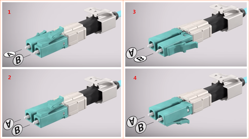
Three Kinds of Polarity Reversal Methods of LC Uniboot Patch Cords

Share

As the networking environment of today becomes increasingly dependent on high-speed and high-density solutions, effective cable management is a real problem. The challenge is how to manage more cables in a smaller amount of space. The LC uniboot patch cord utilises a special “round duplex” cable that allows duplex transmission within a single 2.4mm or 3.0mm cable, which reduces cable management space by up to 70% comparing to standard LC patch cords. Besides, it has a unique polarity reversal design allows the fiber polarity to be easily switched without the use of any tools. In today’s LC uniboot patch cords market, there are usually three methods to reverse the polarity.

Method One
1. Open connector top.

11
2. Switch the polarity.

22
3. Close connector top.

33

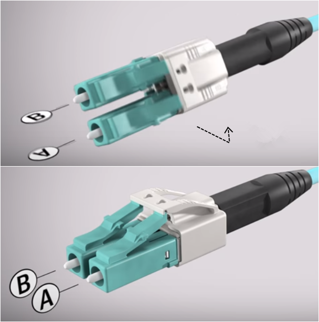
Method Two
1. Locate trigger housing on LC uniboot connector and pull towards the boot.

1
2. Open trigger housing is resting on the boot turn each LC connector to the outside 180 degrees one at a time.

888
3. Complete the polarity reversal by turning the resting trigger housing 180 degrees around boot and click into LC until you hear a click.

000

Method Three
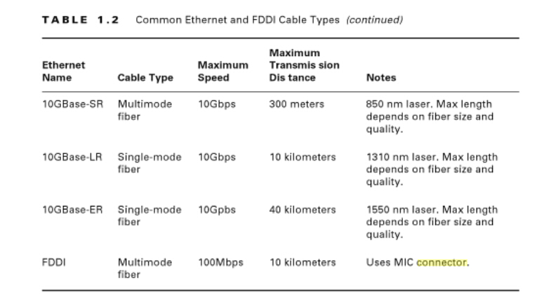
1. Connector Polarity
Uncrossed lines under the connector latch on the housing at both ends indicates uncrossed fiber polarity A-B/B-A.

1
2. Unlock Front Housing on One End
Push the keys on either side to unlock the housing to remove the front section of the Uniboot housing.

2

3. Remove Front Housing
Slide the front housing away from the rest of the Uniboot.

3
4. Rotate Front Housing
Flip the released section of the housing. Do not rotate or twist the fiber.

4
5. Attach Front Housing
Push the housing back over the ends and the rest of the Uniboot connector until it clicks back into place.

5
6. Connector Polarity
Finished result should now show crossed lines under the flipped connector latch and uncrossed lines on the unaltered end. This would indicate a crossed fiber polarity A-A/B-B.

6

Different kind of LC uniboot patch cords may have different polarity reversal design, therefore we must use different method to change the polarity. When you choose to use LC uniboot patch cords in your network, keep in mind to take the polarity reversal methods in to consideration. FS.COM LC uniboot patch cords (easily reverse the polarity with method one) terminated with premium grade zirconia ceramic ferrule connectors which help assure high transmission quality and low optical power loss and offer improved airflow and visibility of equipment within a high-density network environment.

Connectorized Couplings

Share

Quite often it is desirable to have a means of connecting two fibers together through a temporary mating device or connector. Figure 7.4 shows a common way to implement such a connector. Each fiber is placed in a ferrule whose function is to provide the mechanical support for the fiber and hold it in place tightly. The ferrule can be made out of plastic, metal, or ceramic materials. The central piece of the connector itself is an alignment sleeve. The two ferrules are inserted in the sleeve, and proper alignment between the cores is ensured because of the tight mechanical tolerances of the ferrules and the sleeve. The gap between the two fibers can be controlled by a mechanical stop which determines the exact stopping positions of the fibers. In some variations, the alignment sleeve is tapered to improve connector mating and demating.

Well-designed connectors provide low coupling loss, in the order of 0.1 dB or less. However, as shown in Fig. 7.5, a number of underirable situations can reduce the coupling efficiency. Figure 7.5a shows a case of two fibers with different core diameters. In general, whenver the numberical apertures of two fibers are different, the potential for power loss exists. In this case, light coupling from a narrower fiber core to a wide fiber core is easier and more efficient compared to coupling in the other direction. Figure 7.5b shows an example of poor concentricity. Fibers that do not provide a tigh concentricity tolerance may show large coupling variations depending on the orientation or from one pair of fibers to the next.

fiber connector

A large air gap, shown in Fig 7.5c, is another reason for loss of power. An air gap can result from incomplete insertion of the fiber or from mechanical problems inside the sleeve. It is also common for microscopic dust particles to get into fiber optic connector, preventing them from making proper conatact, or even scratching and damaging the fiber facets.

More dramatic power reduction results when dust particles land on the fiber core, blocking the light path. As a result, constant monitoring and cleaning of fiber facets are important to prevent such probems. Angular or lateral displacement, the mechanical tolerances are not tigh enough or when the dimensions of the sleeve and the ferrule do not match.

A fiber connector is characterized by several important parameters. As noted before, the most important factor is insertion loss, or simply connector loss. Another important factor is repeatability. If the same two fibers are connected through the same connector a number of times, each time the coupling will be slightly different. A good connector assmbly provides a small standard deviation for coupling efficiency across multiple insertions. Another desiralbe specification of a fiber connector is low return loss, i.e., a low back reflection. Return loss is defined as the ratio of the reflected power from the connector to the input power. For example, a return loss f 30 dB means 0.001 of the input power is reflected back from the connector. A conector must also be resistant and show a minimal coupling variation in the presence of normal mechanical forces such as axial and lateral forces. This is a practical requirement because in a normal environment it is likely for the connector to encounter a range of mechanical forces.

A wide range of connectors have been designed and are in use in the industry. Here we give an overview of some of the most popular types.

Straight tip or ST connectors are one of the more common type of connectors and in wide use in many applications. The ferrule diameter in an ST connector is 2.5 mm. ST connectors are spring loaded and enaged by a twist-and-lock mechanism.

Fixed connector or FC connectors use an alignment key and a threaded (screw-on) socket and are similar to the popular SMA connectors used in electronics. They are in wide use in single-mode applications and provide low insertion loss and high repeatability.

Subscriber connector, or SC, is another common type of connector. The advantage of SC connectors is that they are engaged by a push-and-snap mechanism, without the need for any roation. This make plugging and unplugging them very easy and also reduces wear out. Moreover, a higher connector density is achieved. Many transceivers provide either an SC receptacle connector, or a pigtail SC connector, as their optical interface. The push-and-snap feature of SC connectors thus provides very convenient and easy way of connecting to optical trasceivers. SC connectors are avaiable in simplex and duplex variations. The ferrule diameter in an SC connector is 2.5 mm.

SC fiber optic patch cable is one of the earliest stype and one of the most commonly used fiber optic cable, it is convenient to use and cost saving, SC fiber optic patch cord is widely uesed in fiber optic networks. SC fiber patch cable is with zirconia sleeve and plastic housing. The common type of SC connector patch cord, there are SC to SC fiber patch cord,  SC to LC Fiber Optic Patch Cable, SC to ST Fiber Optic Patch Cable,  SC to FC Fiber Optic Patch Cable, ect.

The LC or small form factor connector is similar to the SC, but with half the size. The diameter of the ferrule in an LC connector is 1.25 mm, vs 2.5 mm for most other connectors. This allow for twice the connector density for a given space. Because of their compactness, LC connectors have become more popular and are used in many high-end transceivers such as SFPs and XFPs.  LC fiber optic patch cable is with a small form factor (SFF) connector and is ideal for high density applications. LC fiber optic patch cord connector has a zirconia ceramic ferrule measuring 1.25mm O.D. with a PC or APC endface, and provides optimum insertion and return loss.

Related Article:  Which Patch Cable Should I Choose for My Optical Transceiver?

Small Form Factor Fiber-Optic Connectors

Share

One of the more popular styles of fiber-optic connectors is the small form factor (SFF) style of connector. SFF connectors allow more fiber optic terminations in the same amount of space over their standard-sized counterparts. The two most popular are the mechanical transfer registered jack (MT-RJ or MTRJ), designed by AMP, and the Local Connector (LC), designed by Lucent.

MT-RJ

The MT-RJ fiber optic connector was the first small form factor fiber optic connector to see widespread use. It is one-third the size of the SC and ST connectors it msot often replaces. It had the following benefits:

● Small size
● TX and RX strands in one connector
● Keyed for single polarity
● Pre-terminated ends that require no polishing or epoxy
● Easy to use

LC

Local Connector is a newer style of SFF fiber optic connector that is overtaking MT-RJ as fiber optic connector. It is especially popular for use which Fiber Channel adapters and Gigabit Ethernet adapters. It has similar advantages to MT-RJ and other SFF-type connectors but is easier to terminate. It uses a ceramic insert as standard-sized fiber-optic connectors do. Figure 1.21 shows an example of the LC connector. Mentioned fiber optic connector, we know fiber optic patch cords, a fiber optic patch cord is constructed from a core with a high refractive index, surrounded by a coating with a low refractive index that is surrounded by a protective jacket. Transparency of the core permits transmission of optic signals with little loss over great distances. The coating’s low refractive index reflects light back into the core, minimizing signal loss. The protective jacket minimizes physical damage to the core and coating.

Connector design standards include FC, SC, ST, LC, MTRJ, MPO, MU, SMA, FDDI, E2000, DIN4, and D4. Cables are classified by the connectors on either end of the cable; some of the most common cable configurations include FC-FC, FC-SC, FC-LC, FC-ST, SC-SC, and SC-ST.

lc to lc fiber patch cord is used to send high-speed data transmissions throughout your network. LC/LC fiber optic cables connect two components with fiber optic connectors. A light signal is transmitted so there is no outside electrical interference. Our LC/LC fiber optic patch cables are 100% optically tested for maximum performance. We have all lengths and connectors available.

Multimode LC/LC fiber optic patch cable send multiple light signals. They are 62.5/125µ. Common connectors are ST, LC, SC and MTRJ. Our 62.5/125µ LC/LC multi-mode fiber cables can support gigabit ethernet over distances up to 275 meters.

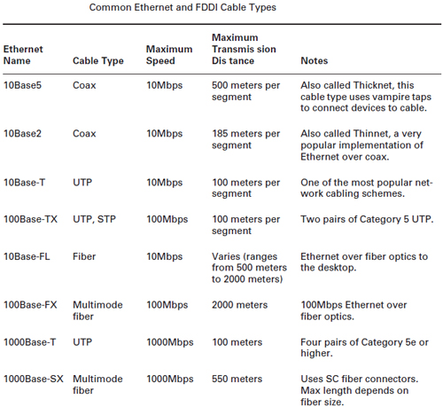
Cable Type Summary

common-ethernet

Fiber optic patch cables are used for linking the equipment and components ,we have fiber optic patch cable with different fiber connector types,our low insertion loss and low back reflection .Axen Technologies fiber patch cable is widely applied in Telecommunication Networks ,Gigabit Ethernet and Premise Installations.

Related Article:  Which Patch Cable Should I Choose for My Optical Transceiver?

Three Types of Cable Connectors Used in Cabling Installation Techniques

Share

There are three types cable connectors in a basic cabling installation techniques: twisted-pair connectors,coaxial cable connectors and fiber-optic connectors. Generally cable connectors have a male component and a female component, except in the case of hermaphroditic connectors such as the IBM data connector. Usually jacks and plugs are symmetrically shaped, but sometimes they are keyed. This means that they have a unique, asymmetric shape or some system of pins, tabs, and slots that ensure that the plug can be inserted only one way in the jack.
Twisted-Pair Cable Connectors

Many people in the cabling business use twisted-pair connectors more than any other type of connector. The connectors include the modular RJ types of jacks and plugs and the hermaphroditic connector employed by IBM that is used with shielded twisted-pair cabling. Twisted-Pair Cable Connectors are used with patch panels, punchdown blocks, and wall plates. Twisted-Pair Cable connector is called an IDC, or insulation displacement connector.
Most unshielded twisted-pair (UTP) and screened twisted-pair (ScTP) cable installations use patch panels and, consequently, 110-style termination blocks. The 110 Blocks (shown in Figure1) contains rows of specially designed slots in which the cables are terminated using a punch-down tool. When terminating 66-blocks, 110-blocks, and often, wall plates, both UTP and ScTP connectors use IDC technology to establish contact with the copper conductors. You don’t strip the wire insulation off the conductor as you would with a screw-down connection. Instead, you force the conductor either between facing blades or onto points that pierce the plastic insulation and make contact with the conductor.

Both UTP and ScTP cables use modular jacks and plugs. For decades, modular jacks have been commonplace in the home for telephone wiring.
Modular connectors come in four-, six-, and eight-position configurations. The number of positions defines the width of the connector. However, often only some of the positions have metal contacts installed. Make sure that the connectors you purchase are properly populated with contacts for your application.
Common Modular-Jack Designations and Their Configuration

Coaxial Cable Connectors
Unless you have operated a 10Base-2 or 10Base-5 Ethernet network, you are probably familiar only with the coaxial connectors you have in your home for use with televisions and video equipment. Actually, a number of different types of coaxial connectors exist.
>>F-Series Coaxial Connectors
The coax connectors used with video equipment are referred to as F-series connectors.The F-connector consists of a ferrule that fits over the outer jacket of the cable and is crimped in place. The center conductor is allowed to project from the connector and forms the business end of the plug. A threaded collar on the plug screws down on the jack, forming a solid connection. F-connectors are used primarily in residential installations for RG-58, RG-59, and RG-6 coaxial cables to provide CATV, security-camera, and other video services.

F-connectors are commonly available in one-piece and two-piece designs. In the two-piece design, the ferrule that fits over the cable jacket is a separate sleeve that you slide on before you insert the collar portion on the cable. Experience has shown us that the single-piece design is superior. Fewer parts usually means less fumbling, and the final crimped connection is both more aesthetically pleasing and more durable. However, the usability and aesthetics are largely a function of the design and brand of the two-piece product. Some two-piece designs are very
well received by the CATV industry.
>>N-Series Coaxial Connectors
The N-connector is very similar to the F-connector but has the addition of a pin that fits over the center conductor; The pin is suitable for insertion in the jack and must be used if the center conductor is stranded instead of solid. The assembly is attached to the cable by crimping it in place. A screw-on collar ensures a reliable connection with the jack. The N-type connector is used with RG-8, RJ-11U, and thicknet cables for data and video backbone applications.

>>The BNC Connector
When coaxial cable distributes data in commercial environments, the BNC connector is often used. BNC stands for Bayonet Neill-Concelman, which describes both the method of securing the connection and its inventors. Many other expansions of this acronym exist, including British Naval Connector, Bayonet Nut Coupling, Bayonet Navy Connector, and so forth. Used with RG-6, RG-58A/U thinnet, RG-59, and RG-62 coax, the BNC utilizes a center pin, as in the N-connector, to accommodate the stranded center conductors usually found in data coax.

The BNC connector comes as a crimp-on or a design that screws onto the coax jacket. As with the F-connector, the screw-on type is not considered reliable and should not be used. The rigid pin that goes over the center conductor may require crimping or soldering in place. The rest of the connector assembly is applied much like an F-connector, using a crimping die made specifically for a BNC connector.

Fiber-Optic Cable Connectors

Fiber-optic connections use different terminology than copper based connectors. The male end of the connection in a fiber-optic system is termed the connector, in contrast to the plug in a copperbased system. The female end of the connection is termed the receptacle or adapter, in contrast to the jack in a copper-based system.
To transmit data up to 10Gbps, two fibers are typically required: one to send and the other to receive. For 40Gbps and 100Gbps over multimode, as many as 24 fibers will be required. Fiber optic connectors fall into one of three categories based on how the fiber is terminated:
•Simplex connectors terminate only a single fiber in the connector assembly.
•Duplex connectors terminate two fibers in the connector assembly.
•Array connectors terminate more than two fibers (typically 12 or 24 fibers) in the connector assembly.

The disadvantage of simplex connectors is that you have to keep careful track of polarity. In other words, you must always make sure that the connector on the “send” fiber is always connected to the “send” receptacle (or adapter) and that the “receive” connector is always connected to the “receive” receptacle (or adapter). The real issue is when normal working folk need to move furniture around and disconnect from the receptacle in their work area and then get their connectors mixed up. Experience has shown us that the connectors are not always color coded or labeled properly. Getting them reversed means, at the least, that link of the network won’t work.

Array and duplex connectors and adapters take care of this issue. Once terminated, color coding and keying ensures that the connector can be inserted only one way in the adapter and will always achieve correct polarity.

Figure2: Some common Fiber Connector

>>The SFF Connector
As transmission rates increase and networks require the cramming in of a greater number of connections, the industry has developed small-form-factor (SFF) connectors and adapter systems for fiber-optic cables. The SC, ST, and FC Fiber Connector shown in Table 10.5 all take up more physical space than their RJ-45 counterparts on the copper side. This makes multimedia receptacle faceplates a little crowded and means that you get fewer terminations (lower density) in closets and equipment rooms than you can get with copper in the same space. The goal for the designers of the SFF connector was to create an optical-fiber connector with the same or lower crosssectional footprint as an RJ-45-style connector in order to increase the number of connections per area (higher density). The LC, the VF-45, and the MT-RJ SFF fiber-optic connectors were initially developed to support the increase in density of fiber connections. The LC Fiber Connector is gaining greater use and is regarded by many optical-fiber professionals.

Several Common Types Of Fiber Optic Cables And Patch Cables

Share

1.FTTH Drop Cable

FTTH (Fiber To The Home), as its name suggests it is a fiber optic directly to the home. Specifically, FTTH refers to the optical network unit (ONU) mounted on home users or business users, is the optical access network application type of closest to users in optical access series except FTTD(fiber to the desktop).

There are 5 main advantages of FTTH:
First, it is a passive network, from the end to the user, the intermediate can be basically passive;
Second, the bandwidth is relatively wide, long distance fits the massive use of operators;
Third, because it is carried business in the fiber, and there is no problem;
Fourth, because of its relatively wide bandwidth, supported protocol is more flexible;
Fifth, with the development of technology, including point-to-point, 1.25G and FTTH have established relatively perfect function.

2. Indoor Fiber Optic Cable

Indoor optical cable is classified according to the using environment, as opposed to outdoor fiber optic cable.

Indoor optical cable is a cable composed of fiber optic (optical transmission medium) after a certain process. Mainly by the optical fiber (glass fiber is as thin as hair),plastic protective tube and plastic sheath. There is no gold, silver, copper and aluminum and other metal, fiber optic cable generally has no recycling value.

Indoor fiber optic cable is a certain amount of fiber optic forming to cable core according to a certain way, outsourcing jacket, and some also coated layer of protection, to achieve a communication line of light signal transmission.

Indoor cable is small tensile strength, poor protective layer, but also more convenient and cheaper. Indoor cable mainly used in building wiring, and connections between network devices.

3. Outdoor Fiber Optic Cable

Outdoor fiber optic cable, used for outdoor environment, the opposite of indoor optical fiber cable.

Outdoor cable is a type of communication line to achieve light signal transmission, is composed of a certain amount of fiber optic forming to cable core according to a certain way, outsourcing jacket, and some also coated with outer protective layer.

Outdoor cable is mainly consists of optical fiber (glass fiber is as thin as hair), plastic protection tube and plastic sheath. There is no gold, silver, copper and aluminum and other metal cable, generally no recycling value.

Outdoor cable is greater tensile strength, thick protective layer, and usually armored(wrapped in metal). Outdoor cables are mainly applied to buildings, and remote networks interconnection.

4.Fiber Optic Patch Cable

Fiber optic patch cable, also known as fiber jumper, used to connect from the device to fiber optic cabling link. Fiber jumper has a thick protective layer, generally used in the connection between the fiber converter and Fiber Termination Box. Commonly used fiber jumpers include: ST, LC, FC and SC.

Main Categories
Single-mode fiber patch cable: General single-mode fiber jumper is colored in yellow, connector and protective sleeve are blue; long transmission distance.

Multi-mode fiber patch cable: General multimode fiber jumper is colored in orange and some in gray, connector and protective sleeve are beige or black and the transmission distance is short.

Fiber optic jumper connector interpretation:
SC Connector: square fiber optical connector;
FC Connector: round with thread;
ST Connector: similar to BNC;
LC Connector: transceiver separation structure;
MT-RJ Connector: square, one with double fiber;
PC Connector: direct contact;
APC Connector:8 degree tilt angle of contact surface;
UPC Connector: arc contact surface.

LC Connector And LC Attenuator

Share

fiber optic connector terminates the end of an optical fiber and enables quicker connection and disconnection than splicing. The fibers are mechanically coupled and aligned to ensure that light can pass.

There has been many different connectors introduced through the development of fiber optic components previously many years. A lot of companies and individuals happen to be trying to improve the options that come with certain connectors to be able to gain control of the fiber optic industry, but only few have been successful. As technology increases, various fiber optic components have become less expensive.

There are various color codes for connectors and they have changed throughout the years. In early stages of fiber optic history, orange, black or grey represented multimode connectors and yellow represented single mode. These original codes became complicated with the introduction of metallic connectors so colored boots were developed, like FC and ST. Now, beige boots stand for multimode, blue means single mode and APC or angled connectors are represented by green boots.

The LC connector is a universal connector. It is available in simplex and duplex configurations and is half how big the SC and utilizes a 1.25mm ferule. The LC is highly favored for single mode and is easily terminated with an adhesive. They’re actively replacing the SC connectors in corporate environments due to their smaller size.

Built on style with LC, LC attenuators really are a combination of a connector on a definite end, as well as an adapter on the other. This enables so that it is “plugged-in” to just about any LC adapter. The assembly contains a ferrule that’s accessible in standard Polish connectors (PC) and 8 degree angle Polish (APC). They’re backward suitable for existing transmission equipment, while the APC attenuators provide superior reflection required for high power and analog equipment. LC fiber optic attenuators are designed to provide horizontal spectral attenuation over the full spectrum vary from 1280nm to 1624nm. This way the LC attenuators expand the capability of optical networks by enabling using the E-band (1400-nm window) for optical transmission.

LC fiber optic attenuator is a passive device accustomed to reduce light signal intensity without significantly changing the waveform itself. It provides a type of metal-ion doped fiber which reduces the noiseless signal because it passes through. This process of attenuation allows for higher performance than fiber splices or fiber offsets or fiber clearance, which function by misdirecting rather than absorbing the joyful signal. This is often a requirement in Dense Wave Division Multiplexing (DWDM) and Erbium Doped Fiber Amplifier (EDFA) applications in which the receiver can’t accept the signal produced by a high-power light source.

LC fiber optic attenuators are key in controlling manipulating the electricity of an optical path in fiber optic telecommunication systems. LC Build-on fiber optic attenuators are used to reduce excess optical power from the transmitter that can result in over-saturation of the receiver.

These optical attenuators feature simple and rugged structure utilizing ion doped fiber because the attenuating material. They can be placed directly on the active equipment and therefore are able to withstand over 1W of extraordinary power light exposure for longer periods of time, which makes them well-suited to EDFA and other high-power applications.