The Wavelength Division Multiplexing (WDM) system is a passive, optical solution for increasing the flexibility and capacity of existing fiber lines in high-speed networks. By adding more channels onto available fibers, the WDM System enables greater versatility for data communications in ring, point-to-point, and multi-point topologies for both enterprise and metro applications. Do you know about WDM system? 5 concepts provided in this blog may help you easily get it.
Optical Transmission
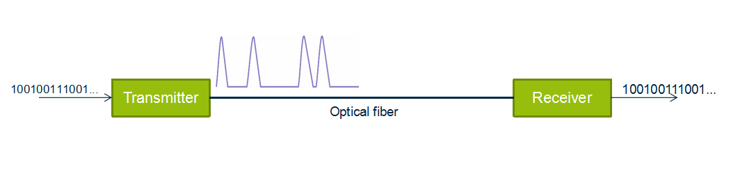
Optical transmission is the conversion of a digital stream of information to light pulses. The light pulses are generated by a laser source (LED or vessel) and transmitted over an optical fiber. The receiver converts the light pulses back to digital information.
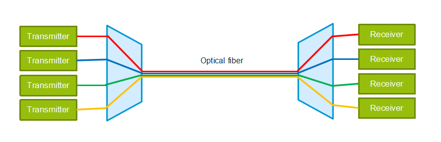
Wavelength Division Multiplexing
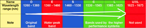
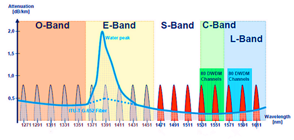
WDM is based on the fact that optical fibers can carry more than one wavelength at the same time. The lasers are transmitting the light pulses at different wavelengths that are combined via filters to one single output fiber. The device used to combine wavelengths is called multiplexer and the device used to separate wavelengths is called demultiplexer, which are the two most basic component in WDM system.
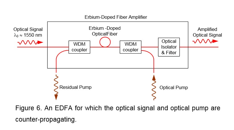
Optical Amplifiers
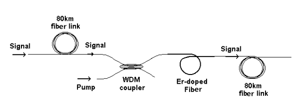
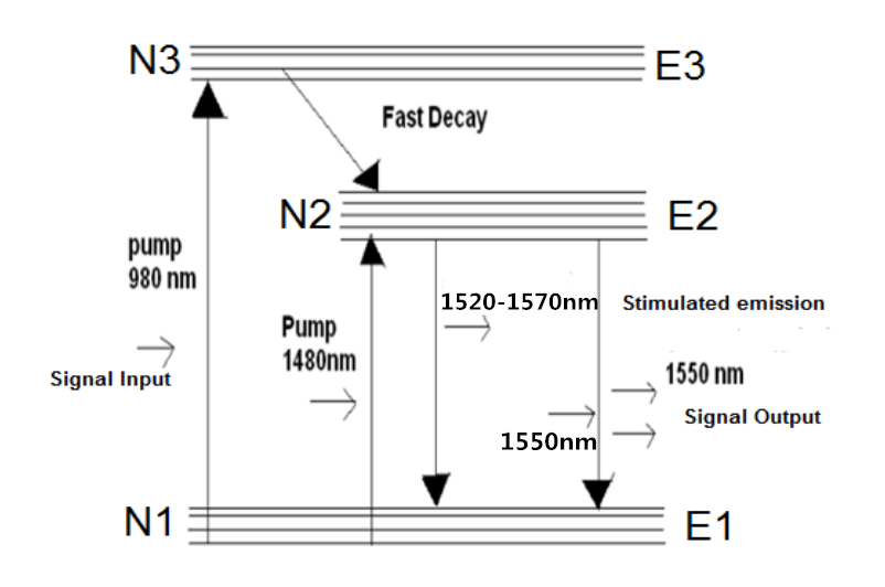
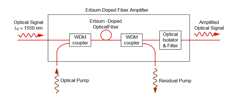
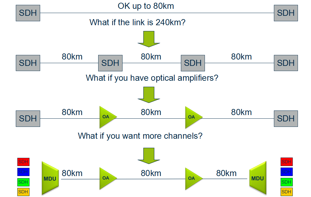
An optical amplifier is a device that amplifies an optical signal directly, without the need to first convert it to an electrical signal. Optical amplifiers boosts the attenuated wavelengths and are more cost efficient than electrical repeaters. Without amplifiers the reach is limited to 80-100km before electrical regeneration. Amplifier stations typically each 80-100km.
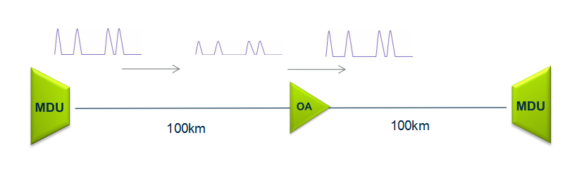
Depending on signal types and fiber characteristics, amplifiers are used in DWDM networks and increases the reach of the optical signals up to 3000 km. Amplifiers are an basic building block for a powerful DWDM network.
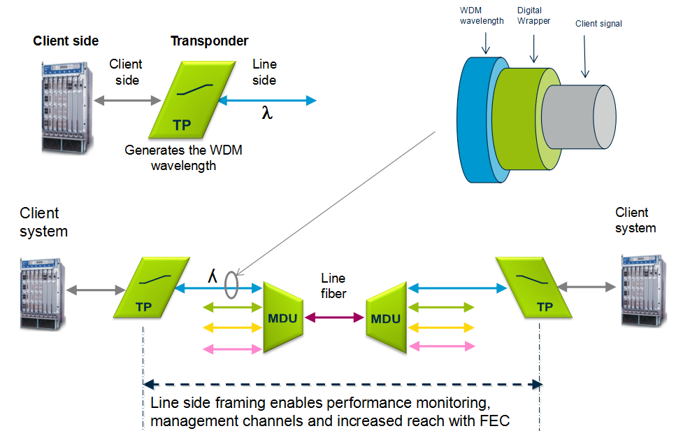
Transponder
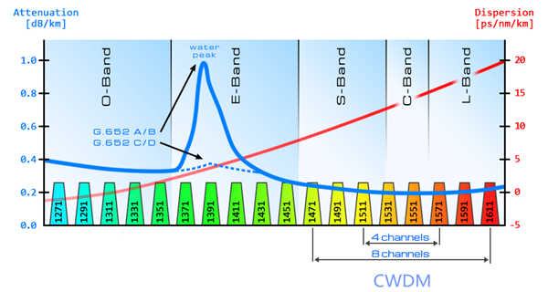
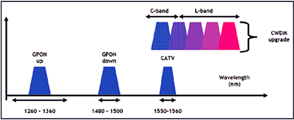
Transponders provides wavelength conversion from client to WDM signal. A transponder maps a single client to a single WDM wavelength. The digital framing of a line signal from a transponder provides service monitoring, management connectivity and increased reach. The broad range of available transponders enables cost efficient solutions for both CWDM & DWDM.
Optical Add Drop Multiplexer
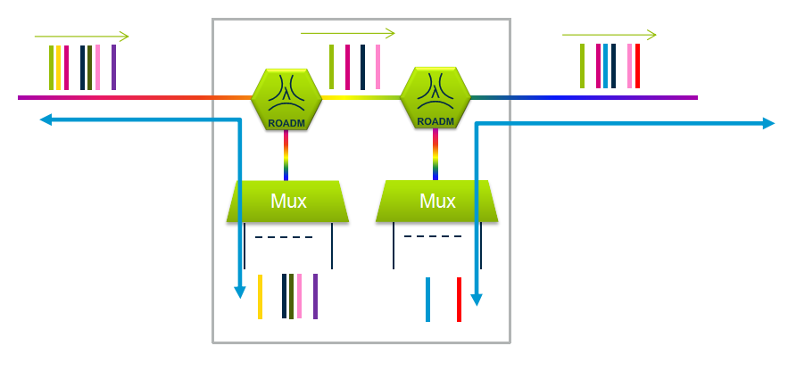
The main function of an optical multiplexer is to couple two or more wavelengths into the same fiber. If a demultiplexer is placed and properly aligned back-to-back with a multiplexer, it is clear that in the area between them, two individual wavelengths exist. This presents an opportunity for an enhanced function, one in which individual wavelengths could be removed and also inserted. Such a function would be called an Optical Add Drop Multiplexer (OADM). OADM is used for increased flexibility in the optical paths. Services can be redirected upon failure or capacity constraints and capacity can be increased dynamically per node.
Conclusion
Multiplexer and demultiplexer are the most basic component in WDM system. If your transmission distance is more than 100 km, an optical amplifier is necessary. If your client wavelength isn’t available for WDM applications, you may need a transponder to convert it to WDM available wavelength. Want to achieve a more flexible, just choose to use a OADM. Besides these, sometimes, a dispersion compensation module is also needed to fix the form of optical signals that are deformed by chromatic dispersion and compensates for chromatic dispersion in fiber that causes the light pulses to spread and generate signal impairment. Do you get WDM system? Just start to build your own WDM system now!