Author Archives: Amelia.Liu

Copper 10GBASE-T Switch Recommendation

Share

In the past few years, network speeds have increased dramatically as applications like video and technologies like virtualization need higher speed and performance. Therefore, 10 Gigabit Ethernet (10GbE) is widely deployed for inter-switch and server-to-switch links. Generally, there are two 10G switch solutions for the aforesaid 10GbE link: 10GBASE-T switch for copper and 10G SFP+ switch. And since the 10GbE copper switch is more favored by the market, this post will focus on copper10GBASE-T  network switch recommendation.

10GBASE-T Switch vs SFP+ Switch: Why Choose 10GBASE-T Copper Link?

Many people may wonder why 10GBASE-T copper link is more favored by the market. This part will discuss this topic in a brief way.

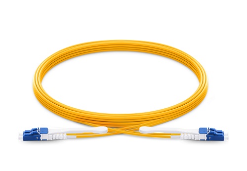
As we all know, copper 10GBASE-T switch uses copper cables to transmit 10Gbps data. This may help to save much money because copper cable infrastructure is far less expensive than the fiber optics of 10G SFP+ switch. In addition, 10GBASE-T network is easier to be employed and allows users to make the best of their existing Cat6a UTP structured cabling ecosystem. Despite all this, 10G SFP+ link also has such advantages as lower latency and lower power budget. For detailed information, you may read 10GBASE-T VS SFP+: Which to Choose for 10GbE Data Center Cabling.

10GBASE-T Switch Recommendation for Copper

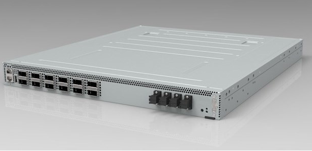
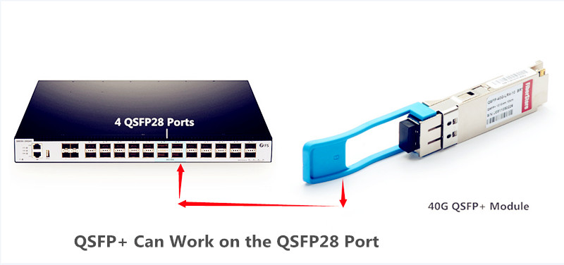
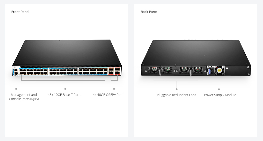
Since 10GBASE-T network is favored by many IT managers, lots of cheap 10GB switch for copper has been supplied in the market. These switches are either 2/4/8/16 port copper switch for home networks or 20+ port 10GBASE-T switch for enterprise and data center networks. This part will introduce a high performance 48 port 10GBASE-T copper switch with 40Gbe QSFP+ UpLink – S5850-48T4Q – for your reference.
Copper 10GBASE-T Switch

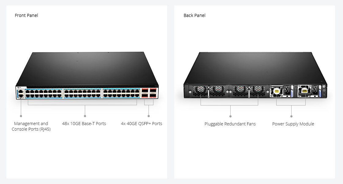
S5850-48T4Q is a 1U managed L2/L3 Ethernet switch. It is designed to meet next generation Metro, Data Center and Enterprise network requirements. Featuring 48 10GBASE-T RJ-45 ports and 4 40G QSFP+ ports, it can provide 1.28Tbps switching capacity. And it has a forwarding rate of 952.32Mpps. The following table compares the key parameters and prices of S5850-48T4Q and other similar switches:

48 port 10GBASE-T Copper Switches

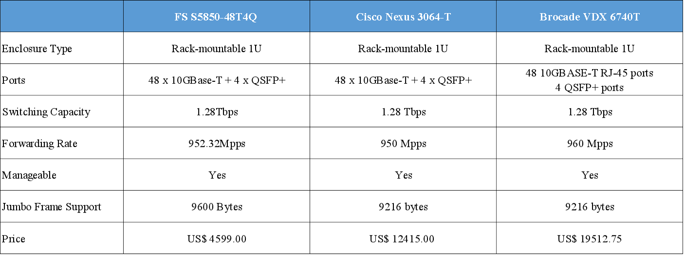
Seen from the above table, you may find that the ports and performance of the three copper 10GBASE-T switches are nearly the same, but Cisco Nexus 3064-T and Brocade VDX 6740T switches are much more expensive than the S5850-48T4Q. This is because their prices include both the actual value of the switch and their specific brands which are always costly. And their after-sale services may be better than most small companies. However, this FS S5850-48T4Q switch is also guaranteed with free tech support and back up support.

S5850-48T4Q 10GBASE-T Switch for Spine-Leaf Application

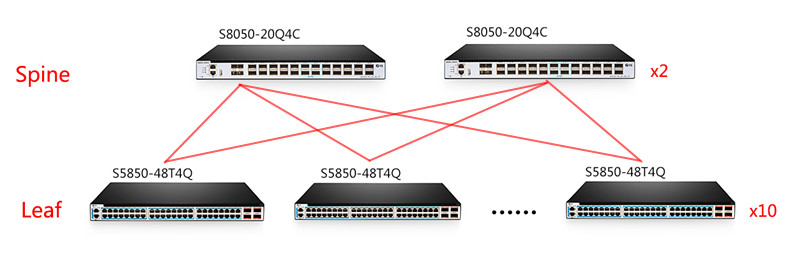
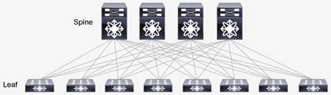
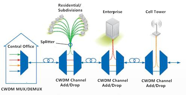
Unlike most copper 10GBASE-T switches, S5850-48T4Q can be used for Spine-Leaf network which is a popular architecture design for data center. To be specific, S5850-48T4Q is often used as the leaf switch in a 40G Spine-Leaf design. As shown below, the 4OG QSFP+ ports of S5850-48T4Q often used to connect to the spine switch (S8050-20Q4C). And the 10GBASE-T copper ports are connect to servers and routers. Read more about Building Spine-Leaf Network with 10GBASE-T Switch

ToR

Conclusion

For lower cost and ease of use, copper 10GBASE-T switch is popular among 10Gb switches. If you plan to migrate to 10GbE network, 10GBASE-T copper network is a good choice. It will help to reduce the cost complexity and cabling issues around the migration to 10GbE in the data center.

Related Article:

Unique Advantages of 10GBASE-T in Migrating Data Center to 10Gb

FS 10GBASE-T Switch: Breaks the Price Barrier for 10G Network 


Different Applications for 10G SFP+ Cable

Share

10G SFP+ cables are of various kinds, including DACs, AOCs, and other 10G SFP+ optics (10GBASE-SR/LR/ER/ZR and 10GBAE-T copper transceivers) plus patch cables and copper cables, which are widely adopted in data centers to connect servers, storage appliance and switches. Each of them has different application for different distance. Next, we will talk about these cables respectively.

10G SFP+ DAC Cable: Server to Switch Connectivity

10G SFP+ DAC cable (Direct Attach Cable) is a type of sheathed high-speed cable featuring SFP connectors on either termination. The main utility of direct attach cables lies in connecting server to switch within the rack. Top-rack interconnections in data centers are made of 10g direct attach cables these days to provide better alternative to RJ 45 connectors, which are losing their foothold because of the bulkier interface and availability of very few equipment and protocol appearing in their compatibility matrix. For any short range connection measuring as small as 5 m to 10 m, a better performing direct attach cable offers easier and more affordable solution. Servers are typically connected to a switch within the same racks. 10G SFP+ DAC twinax cable supports link length up to 7 m, making it perfect for servers to switch connections.

FS 10G SFP+ DAC cables are available with different lengths with customized services being offered too. And every cable is individually tested on corresponding equipment such as Cisco, Arista, Juniper, Dell, Brocade and other brands, having passed the monitoring of FS intelligent quality control system. Part of the products are shown in the picture below.

10G SFP+ AOC Cable: Switch to Switch Connectivity

10G SFP+ AOC cable (Active Optical Cable) assemblies are high performance, cost effective I/O solutions for 10G Ethernet and 10G Fibre Channel applications, which can also be used as an alternative solution to SFP+ passive and active copper cables while providing improved signal integrity, longer distances, superior electromagnetic immunity and better bit error rate performance. They allow hardware manufactures to achieve high port density, configurability and utilisation at a low cost and a reduced power budget. Unlike 10G SFP+ DAC cable, which is often applied in short distance, 10G SFP+ AOC cables can achieve transmission distance up to 100 m, so they often used in switch to switch connections.

10G SFP+ Cables

FS active optical cable (AOC) assemblies use active circuits to support longer distances than standard passive or active SFP+ Copper Cables. FS offers Cisco compatible AOC which is designed for high speed, short range data link via optical fiber wire.

10G SFP+ Optics: Server/Storage to Switch Connectivity

10G SFP+ transceivers, including 10GBASE-SR/LR/ER/ZR and 10GBASE-T copper transceiver, are designed for CWDM and DWDM applications. The range of transceivers supports 850nm, 1310nm, 18 channel for CWDM applications and 40 channels for DWDM applications. These optical transceivers are available with short haul or long haul receivers. Since server or storage to switch connection requires reliable, scalable and high-speed performance, transceivers plus patch cables are usually adopted to achieve such a connection.

10G SFP Cables

FS 10G transceivers are of various types, including GBIC, SFP+, XFP, X2, XENPAK optics, which can be deployed in diverse networking environments. With an industry-wide compatibility and strict test program, FS 10G SFP+ modules can give customers a wide variety of 10 Gigabit Ethernet connectivity options such as server/storage to switch connectivity.

Conclusion

Different 10G SFP+ cables are selected for different distance and application. Generally speaking, 10G SFP+ DAC cable is perfect for short reach applications within racks, while 10G SFP+ AOCs are suitable for inter-racks connections between ToR and EoR switches. With excellent quality and lifetime warranty, FS 10G optics brings real-time network intelligence to the financial services market at 10 Gbps speeds. All the products mentioned in the previous text are in stock. For more information, please visit us at www.fs.com.

Related Article: 10G SFP+ Cable for High Speed Data Center

                            SFP+ DAC Twinax Cable Deployment Considerations


Cloud vs Data Center: What’s the Difference?

Share

Many people may be confused about what is cloud computing and what is data center. They often ask questions like, “Is a cloud a data center?”, “Is a data center a cloud?” or “Are data center and cloud computing two completely different things?” Maybe you know your company needs the cloud and a date center. And you also know your data center needs the cloud and vice versa. But you just don’t know why! Don’t worry. This essay will help you have a thorough understanding of the two terms and tell you the difference between cloud vs data center. Let’s begin with their definition first.

Cloud vs Data Center: What Are They?
cloud computing vs data center

The term “data center” can be interpreted in a few different ways. First, an organization can run an in-house data center maintained by trained IT employees whose job is to keep the system up and running. Second, it can refer to an offsite storage center that consists of servers and other equipment needed to keep the stored data accessible both virtually and physically.

While the term “cloud” or “cloud computing” didn’t exist before the advent of Internet. Cloud computing changes the way businesses work. Rather than storing data locally on individual computers or a company’s network, cloud computing entails the delivery of data and shared resources via a secure and centralized remote platform. Rather than using a company’s own servers, it places its resources in the hands of a third-party organization that offers such a service.

Cloud vs Data Center in Security
Cloud Computing vs Data Center

Since the cloud is an external form of computing, it may be less secure or require more work to ensure security than a data center. Unlike data centers, where you are responsible for your own security, you will be entrusting your data to a third-party provider that may or may not have the most up-to-date security certifications. If your cloud are placed on several data centers in different locations, each location will also need the proper measures to ensure the security.

A data center is also physically connected to a local network, which makes it easier to ensure that only those with company-approved credentials and equipment can access stored apps and information. The cloud, however, is accessible by anyone with the proper credentials anywhere that there is an Internet connection. This opens a wide array of entry and exit points, all of which need to be protected to make sure that data transmitted to and from these points are secure.

Cloud VS Data Center in Cost
difference between cloud vs data center

For most small businesses, cloud computing is a more cost-effective option than a data center. Because when you chose a data center, you have to build an infrastructure from the start and will be responsible for your own maintenance and administration. Besides, a data center takes much longer to get started and can cost businesses $10 million to $25 million per year to operate and maintain.

Unlike a data center, cloud computing does not require time or capital to get up and running. Instead, most cloud computing providers offer a range of affordable subscription plans to meet customers’ budget and scale the service to their actual needs. And data centers take time to build,  whereas cloud services are available for use almost immediately after registration.

Conclusion

Going forward, cloud computing services will become increasingly attractive with a low cost and convenient service. It creates a new way to facilitate collaboration and information access across great geographic distances while reducing the costs. Therefore, compared cloud computing vs data center, the future of cloud computing is definitely much brighter.

Related Article: The Evolution of Data Center Switching

Are White Box Switches Equal to OEM Switches?

Share

With a low cost and excellent performance, white box switch has been a hot topic in the past few years. However, the basic definition of white box switch is still vague and ambiguous as a result of various reasons. Firstly, no one has ever made an accurate and standard conception of white box switches before; secondly, manufacturer with different interests and demands will deliberately obscure the definition of white box switch; thirdly, people who are unaware of the truth of Internet tend to be wrongly informed, which also lead to chaos in its definition. Some even simply equate a white box switch with an OEM switch. So what is a white box switch exactly?

white box switch

How to Understand White Box Switches?

According to its literal meaning, white box switches refer to network switch without a label. However, there exists a deep connotation in white box switches which means this kind of switches doesn’t focus on brand. Based on this core idea, to better understand white box switches, here we might as well divide them into the following three models:

  • Bare-mental switch. It is the fundamental type of white box switch with no network operating system loaded on them except a boot loader. Customers can purchase a software through a third party like Big Switch, Cumulus, and Pica8 or even write a software by themselves. They ask for hardware support from hardware vendors and software support from software vendors.
  • White box switch. In this model, the supplier will offer switches with both hardware and software (the supplier only provide one of them, either hardware or software, but they got the authority of another from their partners). So customers can seek support for both hardware and software from one supplier. Besides, there are options for customers to choose for both hardware and software.
  • OEM switches. The hardware and software of the switch are manufactured and provided by an OEM (original equipment manufacturer). These OEMs design and manufacture a switch as specified by another company to be rebranded or not branded. This kind of switch is also called white box switch by many people. And suppliers offering this service are called white box supplier, especially when the supplier is small and not well-known.
The Market for White Box Switches

With a wide choice of networking software based on low-cost, commodity hardware, white box switches are bound to have a vast market in the future. Also, with the deployment of SDN, there is an increasing interest in white box switches within the IT community. In the previous text, we have divided white box switches into three types. Next, I will analyze the market for white box switches based upon this classification.

The market for white box switches

  • Bare-mental switches have been most widely used with a customer group mainly from networking giants like Google, Facebook, and Microsoft. They purchase a bare-mental switch and develop networking software by themselves. In china, large companies like Baidu, Alibaba, Tecent, and JD also tried this model, with Baidu being the most successful example. The reason why these giants chose such a kind of white box switch is that they are confident and capable enough to handle the development and operation of the software for a switch. Besides, these major technology firm have an extremely large-scale network, which requires them to control the network completely by themselves.
  • The customers for the second type are mainly distributed abroad with only a few in China. They mainly come from large financial companies, international data corporation and some network operators, whose size may only behind those internet giants. Cost saving is the most important driving force for them to buy a white box switch. Also, part of these enterprises chose it just for the differentiated operating system provided by white box suppliers who are willing to satisfy their specific demands through customized service.
  • The customer for the third type is distributed both at home and abroad. Although the market for this part is smaller than the first two, it has the largest potential for its customer group involving a large number of VARs (value added resellers), system integrators, IT products providers and many medium-sized clients. They adopt a white box switch for varied reasons such as improving the production line and saving costs.
Summary

Through this essay, we can see clearly that white box switch is much more than an OEM switch and the latter can be classified as one kind of the former. With a lower cost, excellent performance and huge market potential, white box switch will definitely grow up as the mainstream for switch adoption.

The Evolution of Data Center Switching

Share

Today, the traditional three-tier data center switching design has developed as a mature technology which had been widely applied. However, with the rapid growth in technology, the bottlenecks and limitations of traditional three-tier architecture keep emerging and more and more network engineers choose to give up such a kind of network architecture. So what’s the next best option for data center switching? The answer is leaf-spine network. For many years, data center networks have been built in layers that, when diagrammed, suggesting a hierarchical tree. As this hierarchy runs up against limitations, a new model is taking its place. Below, you will see a quick comparison between the two architectures, how they’ve changed and the evolution of data center switching.

Traditional Three-Tier Architecture

data center switching

Traditional three-tier data center switching design historically consisted of core Layer 3 switches, aggregation Layer 3 switches (sometimes called distribution Layer 3 switches) and access switches. Spanning Tree Protocol was used between the aggregation layer and the access layer to build a loop-free topology for the Layer 2 part of the network. Spanning Tree Protocol had a lot of benefits including a relatively easy implementation, requiring little configuration, and being simple to understand. Spanning Tree Protocol cannot use parallel forwarding paths however, it always blocks redundant paths in a VLAN. This impacted the ability to have a highly available active-active network, reduced the number of ports that were usable, and had high equipment costs.

The Fall of Spanning Tree Protoco

From this architecture, as virtualization started to grow, other protocols started to take the lead to allow for better utilization of equipment. Virtual-port-channel (vPC) technology eliminated Spanning Tree blocked ports, providing an active-active uplink from the access switches to the aggregation Layer 3 switches, and made use of the full available bandwidth. The architecture also started to change from the hardware standpoint by extending the Layer 2 segments across all of the pods. With this, the data center administrator can create a central, more flexible resource pool that can be allocated based on demand and needs. Some of the weaknesses of three-tier architecture began to show as virtualization continued to take over the industry and virtual machines needed to move freely between their hosts. This traffic requires efficiency with low and predictable latency. However, vPC can only provide two parallel uplinks which leads to bandwidth being the bottleneck of this design.

The Rise of Leaf-Spine Topology

Spine-and-Leaf-Topology-Data-Center-Switching

Leaf-spine topology was created to overcome the bandwidth limitations of three-tier architecture. In this configuration, every lower-tier network switch (leaf layer) is connected to each of the top-tier switches (spine layer) in a full-mesh topology. The leaf layer consists of access switches that connect to servers and other devices. The spine layer is the backbone of the network and is responsible for interconnecting all leaf switches. Every leaf switch is connected to every spine. There can be path optimization so traffic load is evenly distributed among the spine. If one spine switch were to completely fail, it would only slightly degrade performance throughout the data center. Every server is only a maximum number of hops from any other server in the mesh, greatly reducing latency and allowing for a smooth vMotion experience.

Leaf-spine topology can also be easily expanded. If you run into capacity limitations, expanding the network is as easy as adding an additional spine switch. Uplinks can be extended to every leaf switch, resulting in the addition of interlayer bandwidth and reduction of oversubscription. If device port capacity becomes a concern, a new leaf switch can be added. This architecture can also support using both chassis switches and fixed-port switches to accommodate connectivity types and budgets. One flaw of the spine-and-leaf architecture, however, is the number of ports needed to support each leaf. When adding a new spine, each leaf must have redundant paths connected to the new spine. For this reason, the number of ports needed can grow incredibly quickly and reduces the number of ports available for other purposes.

Conclusion

Now, we are witnessing a change from the traditional three-tier architecture to a spine-and-leaf topology. With the increasing demand in your data center and east-west traffic, the traditional network topology can hardly satisfy the data and storage requirements. And the increasingly virtual data center environments require new data center-class switches to accommodate higher throughput and increased port density. So you may need to purchase a data center-class switch for your organization. Even if you don’t need a data center-class switch right now, consider it next year. Eventually, server, storage, application and user demands will require one. The best-value and cost-efficient data center switch for your choice at FS.com.

Can I Use the QSFP+ Optics on QSFP28 Port?

Share

100G Ethernet will have a larger share of network equipment market in 2017, according to Infonetics Research. But we can’t neglect the fact that 100G technology and relevant optics are still under development. Users who plan to layout 100G network for long-hual infrastructures usually met some problems. For example, currently, the qsfp28 optics on the market can only support up to 10 km (QSFP28 100GBASE-LR4) with WDM technology, which means you have to buy the extra expensive WDM devices. For applications beyond 10km, QSFP28 optical transceivers cannot reach it. Therefore, users have to use 40G QSFP+ optics on 100G switches. But here comes a problem, can I use the QSFP+ optics on the QSFP28 port of the 100G switch? If this is okay, can I use the QSFP28 modules on the QSFP+ port? This article discusses the feasibility of this solution and provides a foundational guidance of how to configure the 100G switches.

For Most Switches, QSFP+ Can Be Used on QSFP28 Port

As we all know that QSFP28 transceivers have the same form factor as the QSFP optical transceiver. The former has just 4 electrical lanes that can be used as a 4x10GbE, 4x25GbE, while the latter supports 40G ( 4x10G). So from all of this information, a QSFP28 module breaks out into either 4x25G or 4x10G lanes, which depends on the transceiver used. This is the same case with the SFP28 transceivers that accept SFP+ transceivers and run at the lower 10G speed.

QSFP can work on the QSFP28 ports

A 100G QSFP28 port can generally take either a QSFP+ or QSFP28 optics. If the QSFP28 optics support 25G lanes, then it can operate 4x25G breakout, 2x50G breakout or 1x100G (no breakout). The QSFP+ optic supports 10G lanes, so it can run 4x10GE or 1x40GE. If you use the QSFP transceivers in QSFP28 port, keep in mind that you have both single-mode and multimode (SR/LR) optical transceivers and twinax/AOC options that are available.

In all Cases, QSFP28 Optics Cannot Be Used on QSFP+ Port

SFP+ can’t auto-negotiate to support SFP module, similarly QSFP28 modules can not be used on the QSFP port, either. There is the rule about mixing optical transceivers with different speed—it basically comes down to the optic and the port, vice versa. Both ends of the two modules have to match and form factor needs to match as well. Additionally, port speed needs to be equal or greater than the optic used.

How to Configure 100G Switch?

For those who are not familiar with how to do the port configuration, you can have a look at the following part.

  • How do you change 100G QSFP ports to support QSFP+ 40GbE transceivers?

Configure the desired speed as 40G:
(config)# interface Ethernet1/1
(config-if-Et1/1)# speed forced 40gfull

  • How do you change 100G QSFP ports to support 4x10GbE mode using a QSFP+ transceiver?

Configure the desired speed as 10G:
(config)# interface Ethernet1/1 – 4
(config-if-Et1/1-4)# speed forced 10000full

  • How do you change 100G QSFP ports from 100GbE mode to 4x25G mode?

Configure the desired speed as 25G:
(config)# interface Ethernet1/1 – 4
(config-if-Et1/1-4)# speed forced 25gfull

  • How do you change 100G QSFP ports back to the default mode?

Configure the port to default mode:
(config)# interface Ethernet1/1-4
(config-if-Et1/1)# no speed

Note that if you have no experience in port configuration, it is advisable for you to consult your switch vendor in advance.

Conclusion

To sum up, QSFP+ modules can be used on the QSFP28 ports, but QSFP28 transceivers cannot transmit 100Gbps on the QSFP+ port. When using the QSFP optics on the QSFP28 port, don’t forget to configure your switch (follow the above instructions). To make sure the smooth network transmission, you need to ensure the connectors on both ends are the same and no manufacturer compatibility issue exists.

The Basics of 1000BASE-SX and 1000BASE-LX SFP

Share

Gigabit Ethernet has been regarded as a huge breakthrough of telecom industry by offering speeds of up to 100Mbps. Gigabit Ethernet is a standard for transmitting Ethernet frames at a rate of a gigabit per second. There are five physical layer standards for Gigabit Ethernet using optical fiber (1000BASE-X), twisted pair cable (1000BASE-T), or shielded balanced copper cable (1000BASE-CX). 1000BASE-LX and 1000BASE-SX SFP are two common types of optical transceiver modules in the market. Today’s topic will be a brief introduction to 1000BASE-LX and 1000BASE-SX SFP transceivers.

1000BASE in these terms refers to a Gigabit Ethernet connection that uses the unfiltered cable for transmission. “X” means 4B/5B block coding for Fast Ethernet or 8B/10B block coding for Gigabit Ethernet. “L” means long-range single- or multi-mode optical cable (100 m to 10 km). “S” means short-range multi-mode optical cable (less than 100 m).

1000BASE-SX
1000BASE-SX is a fiber optic Gigabit Ethernet standard for operation over multi-mode fiber using a 770 to 860 nanometer, near infrared (NIR) light wavelength. The standard specifies a distance capability between 220 meters and 550 meters. In practice, with good quality fiber, optics, and terminations, 1000BASE-SX will usually work over significantly longer distances. This standard is highly popular for intra-building links in large office buildings, co-location facilities and carrier neutral internet exchanges. 1000BASE-SX SFP works at 850nm wavelength and used only for the purposed of the multimode optical fiber with an LC connector. 1000BASE-SX SFP traditional 50 microns of multimode optical fiber link is 550 meters high and 62.5 micron fiber distributed data interface (FDDI) multimode optical fiber is up to 220 meters. Take EX-SFP-1GE-SX as an example, this SX fiber transceiver supports DOM function and the maximum distance of the SX SFP is 550 m. The 1000Base-SX standard supports the multimode fiber distances shown in table 1.

1000Base-SX standard

1000BASE-LX
Specified in IEEE 802.3 Clause 38, 1000BASE-LX is a type of standard for implementing Gigabit Ethernet networks. The “LX” in 1000BASE-LX stands for long wavelength, indicating that this version of Gigabit Ethernet is intended for use with long-wavelength transmissions (1270–1355 nm) over long cable runs of fiber optic cabling. 1000BASE-LX can run over both single mode fiber and multimode fiber with a distance of up to 5 km and 550 m, respectively. For link distances greater than 300 m, the use of a special launch conditioning patch cord may be required. 1000BASE-LX is intended mainly for connecting high-speed hubs, Ethernet switches, and routers together in different wiring closets or buildings using long cabling runs, and developed to support longer-length multimode building fiber backbones and single-mode campus backbones. E1MG-LX-OM is Brocade 1000BASE-LX SFP, this LX single-mode transceiver  operates over a wavelength of 1310nm for 10 km.

1000BASE-LX SFP

Difference Between LX, LH and LX/LH
Many vendors use both LH and LX/LH for certain SFP modules, this SFP type is similar with the other SFPs in basic working principle and size. However, LH and LX/LH aren’t a Gigabit Ethernet standard and are compatible with 1000BASE-LX standard. 1000BASE-LH SFP operates a distance up to 70km over single-mode fiber. For example, Cisco MGBLH1 1000BASE-LH SFP covers a link length of 40km that make itself perfect for long-reach application. 1000BASE-LX/LH SFP can operate on standard single-mode fiber-optic link spans of up to 10 km and up to 550 m on any multimode fibers. In addition, when used over legacy multimode fiber type, the transmitter should be coupled through a mode conditioning patch cable.

Conclusion
1000BASE SFP transceiver is the most commonly used component for Gigabit Ethernet application. With so many types available in the market, careful notice should be given to the range of differences, both in distance and price of multimode and single-mode fiber optics. Fiberstore offers a large amount of in-stock 1000BASE SFP transceivers which are compatible for Cisco, Juniper, Dell, Finisar, Brocade, or Netgear in various options. If you have any requirement of our products, please send your request to us.

Related Article: Can We Interconnect SFP, SFP+, XFP, X2 and XENPAK?

Related Article: How Many Types of SFP Transceivers Do You Know

How to Handle Challenges of CWDM Network Testing?

Share

CWDM technology has proven itself to be a cost-effective and simplified method for network managers to optimize the existing infrastructure. The adoption of CWDM system into metro and regional network is constantly on the rise and it also extends the reach to the access networks. CWDM is becoming more widely accepted as an important transport architecture owing to its lower power dissipation, smaller size, and less cost. This article will focus on the challenges concerning CWDM network testing, and provide several methods to help overcome them.

Basic Configurations of CWDM Network

CWDM configuration is usually based on a single-fiber pair: one fiber is for transmitting and the other for receiving. The following figure shows the most basic configuration of optical network with 4 channel CWDM MUX/DEMUX: it often delivers eight wavelengths, from 1471 nm to 1611 nm, with 20 nm apart. A CWDM architecture is quite simple. It only has passive components like multiplexers and demultiplexers, without any active elements such as amplifiers. However, using CWDM as a means of increasing bandwidth also brings network characterization and deployment challenges, which will be discussed in the following section.

cwdm basic configuration

Challenges and Solutions for CWDM Testing

The challenges of CWDM network testing mainly lie in three phases: construction and installation, system activation and upgrade or troubleshoot. Here we provide solutions for each.

Challenge One: Construction and Installation

During construction and installation process, it is essential to conduct physical-layer tests on the fiber from the head-end to the destination. Single-ended testing with an OTDR is definitively an advantage as it optimizes labor resources. In this case, the objectives are to characterize the entire link (not only the fiber) to include the add-drop multiplexers (OADM) and to guarantee continuity up to the final destination. However, testing at standard OTDR wavelengths, such as 1310 nm and 1550 nm, cannot be done in such conditions as these wavelengths are filtered out at either OADM, never reaching the end destination. Then how to test such a link?

cwdm otdr testing

Solution: Adopting a specialized CWDM OTDR. With CWDM-tuned wavelength, the CWDM OTDR is capable of performing an end-to-end test by dropping each test wavelength at the correspondent point on the network, allowing the characterization of each part of the network directly from the head-end. Which is considered time and labor saving since one don’t have to access. It also helps to speed up the deployment process as the technician will test all drop fibers from a single location.

Challenge Two: System Activation

Since CWDM network architecture is rather basic which contains no active components like amplifiers, the only things that can prevent proper transmission in a CWDM network system are transmitter failure, sudden change in the loss created in an OADM or manual errors, bad connections for example. To deal with these problems, one has to look at the signal being transmitted.

Solution: A CWDM channel analyzer is ideal to handle this challenge. It works to quickly determine the presence or absence of each of the 16 wavelengths and their power levels. Many CWDM OADM have tap ports, which means that there is a port where a small portion of the signal is dropped. Taps are typically 20 dB weaker than the main signal. If these taps are not present, a CWDM analysis should be performed. It consists of unplugging the end user to use the main feed for the analysis. To be ready for all possibilities, a CWDM channel analyzer should cover a power range going as low as –40 dBm, while being able to test the entire wavelength range in the shortest time as possible.

Challenge Three: Upgrade or Troubleshoot

In the maintenance and troubleshoot phrase, when the network is live and a new wavelength is added, one should figure out two questions: is the link properly set up? And is my wavelength presents and well?

out-of-band testing of cwdm

Solution: Two approaches are available to check if a link is set up properly: a CWDM OTDR approach or an out-of-band approach. The CWDM OTDR approach is relatively simple when a new customer is added. With CWDM OTDR, one can perform CWDM network testing without having to wait for the customer or to go to the cell tower sites. The wavelength can be turned on at the head-end. Which speed testing process greatly.

The OTDR and channel analyzer combo are also useful when a single customer has issues. The channel analyzer will reveal if the channel is indeed present and within power budget. If not, the CWDM OTDR can be used to test at that specific wavelength or an out-of-band 1650 nm OTDR test can be performed from the customer’s site to detect any anomalies on the link, all without disconnecting the head-end since the OADM will filter out the 1650 nm, therefore not affecting the remainder of the network.

Conclusion

CWDM testing challenges may be inevitable during each phase of the deployment, but with specialized equipment, these challenges can be overcomed completely. Tools including a CWDM OTDR, a CWDM channel analyzer and an out-of band OTDR are proved effective and valuable to reduce downtime and increase bandwidth at a minimum cost.

How to Achieve 10GB in Your Home Lab Under $70?

Share

A lot of small to medium businesses haven’t made the transition over to 10Gb speeds from the typical 1Gb (at least around where I live), let alone us homelabbers, because of it’s cost. Even with “cheaper” 10GBASE-T switches coming out, like the D-Link DXS-1210-12TC, $1,470 is still a lot more than most of us can convince our wives to let us spend on one. Also, do you have 10Gb NICs on your hosts and NAS/SANs? What about the right cables? These things aren’t cheap.

Inspired by a Reddit post I found over on the /r/homelab subreddit, I decided to try a 10Gb point-to-point connection between my ESXi host (a Dell PowerEdge R520) and my HP ProLiant DL320e that I’m using as my mini-SAN (running Windows Server 2016 TP4). For those that don’t know, a point-to-point connection is a small network between two endpoints or clients, so no switch is needed. My switch (an HP ProCurve 2920) doesn’t have the 10Gb modules needed but I wanted the 10Gb connection between my ESXi host and SAN anyway, so a P2P connection between those two would be perfect.

The NICs talked about in the /r/homelab thread were used HP Mellanox ConnectX-2 10GbE NICs you can find on eBay for SUPER cheap (currently $18.78 each on eBay) connected via this 10GBASE SFP+ cable for $22.94 shipped. I found the NICs to be widely supported but I couldn’t find a lot of information on just how supported they are on the newest operating systems. My host is running ESXi 6 while my ProLiant is running Windows Server 2016 TP4, but for a total of about $65, it was worth the risk of not being supported.

UPDATE: Thanks to Reddit user /u/negabiggz for mentioning that these Mellanox ConnectX-2 NICs do not work under FreeNAS. If you’d still like to create a cheap 10Gb P2P connection in FreeNAS, you can pick up these Chelsio S310E-CR 10Gb NICs on eBayor (shown in figure below) wait till the drivers are natively supported in version 10.1.

Chelsio S310E-CR 10Gb NICs

About a week after placing the orders for the NICs and cable, these two beautiful pieces of used hardware came in along with the SFP+ cable. I immediately took the R520 and ProLiant DL320e out of my rack and got them both easily installed. I fired both machines up and got what every sysadmin and/or homelabber loves to see: both NICs working properly out of the box. Turns out ESXi 6 AND Server 2016 TP4 really do support these cheap, beautiful NICs without the need to install/uninstall/reinstall a ton of different drivers.

maul

This is a screenshot of the 10Gb NIC on my ProLiant right after booting it up and configuring the static IP.

esxi
This is a screenshot of the NIC on my ESXi host after booting it up and getting the other NIC configured on my 2016 TP4 box.

I haven’t done a lot of speed tests to get the official read/write speeds, but I have added the 10Gb NIC to my media downloading VM and transferred a few 720p TV episode files between them and my ProLiant. I tried to take a screenshot of the transfer rate when I copied over a 1GB 720p episode of a TV show I downloaded (legitimately, I swear!), but the screen never came up. I didn’t even get a chance to screenshot it. It was like I just moved the video between folders on the same drive. I also configured an iSCSI connection using the 10Gb link and performance so far has been great.

So there you have it. An awesome 10Gb speed on your homelab all for under $70. Thanks to the /r/homelab community for the idea and for suggesting the hardware, especially for those of us that didn’t want to convince our wives why we need to spend hundreds of dollars so we can transfer files using a puny 1Gb connection.

Source: https://thatservernerd.com/2016/02/23/10gb-in-your-homelab-for-under-70

Frequently Asked Question About Fiber Patch Cord

Share

What Is Fiber Patch Cord?

A fiber patch cord can be a cable that connects devices allowing information to pass together. Patch cords certainly are a common method of setting up wired connections between devices, including connecting a tv with a digital cable box using coaxial cable. These cords are used for any kind of signal transference, such as in a television, radio or computer network. These cables are manufactured with standard fiber optic cabling and are terminated with fiber optic connectors for both ends.

fiber patch cord

What Is Fiber Patch Cord Used for?

There are several application areas for optical fiber cable, including connecting computer workstations to outlets and connecting fiber optic patch panels or optical cross-connect distribution centers.

What Are the Most Common Fiber Optic Patch Cables?

There are lots of common forms of fiber patch cables and your network may need a number of these phones operate most efficiently. Professionals use a number of ways to categorize the most frequent fiber patch cables, like the fiber cable type, the termination connector types, the optical fiber modes, the dimensions of the fiber cable, as well as the various styles of polishing the connectors. FS.COM offer several types of common patch cable, it provides 10G OM3/OM4 fiber patch cable; 9/125 single-mode and OM2 50/125, OM1 62.5/125 multimode fiber patch cable having a number of connector types including LC, SC, ST, FC, MU, and MTRJ.

What Are Fiber Optic Cable Types?

There are the main kinds of fiber cable: Simplex, Duplex. A Simplex fiber patch cable has one fiber and one connector on each side. A Duplex fiber optic cable features two fibers and a couple connectors on both ends. Either each fiber will probably be marked separately (e.g., A and B) or the connector boots uses different colors to think the polarity of each connector.

How Are Fiber Optic Patch Cables Terminated?

You can find basically two methods to terminate a fiber cable: utilizing the same connector type on both ends from the cable (e.g., LC fiber patch cable: LC to LC) and taking advantage of two different connectors on each side from the cable (e.g. ST-SC fiber patch cable) which is also known as the Hybrid termination.

What Are the Most Common Connector Types for Fiber Patch Cord?

Typically the most popular connector types are SC, ST, LC, MTRJ, MU, and FC.

What Modes Are Utilized in Fiber Patch Cord?

Currently, there are three different modes which can be used in fiber patch cords: single mode, multimode, and 10G multimode. Single mode fiber cables count on 9/125 micron fiber cable with single mode connectors on both ends with the cable. Multimode fiber optic patch cables use 62.5/125 micron or 50/125 micron fiber cabling and therefore are terminated with multimode fiber optic connectors on each end of the cable. 10Gb multimode fiber optic patch cords use enhanced 50/125 micron fiber that is optimized for 850nm VCSEL based 10Gb Ethernet. They are usually suitable for existing network equipment and will offer 300% more bandwidth than traditional 62.5/125 multimode fibers. These cables will also be rated for distances up to 300 meters.

Why Are There Different Connector Polishing Styles?

Fiber optic connectors were created, manufactured and polished to different shapes to reduce back reflection. Back reflection grades generally vary from -30dB to -60dB. Remember that polishing is especially important for applications in which single mode fiber has been used.

What Are Other Names for Fiber Patch Cord?

This really is by no means a thorough list of synonyms of these cables, but we now have heard them called: fiber optic patch cords, fiber patch cables, fiber optic jumpers, fiber jumper cables, duplex fiber jumpers, fiber wire, LAN fiber, network fiber, optic cables, network glass, plus more.

What Information Should I Provide If I Want to Modify the Fiber Patch Cord?

The following:

1. Quantity, and Length in meters.

2. The number of fibers. Simplex or Duplex.

3. Connector type for both ends, they could ‘t be exactly the same on both ends.

4. Singlemode or Multimode fiber. If Multimode please advise if 62.5/125 or 50/125, or 50/125 laser optimized.

5. PVC or Plenum jacket.

6. It is possible to send your customized detail info to the email: sales@fs.com, our sales will contact you as soon as possible, many thanks.