Tag Archives: transceiver module

400G OTN Technologies: Single-Carrier, Dual-Carrier and Quad-Carrier

Share
400G

In order to achieve 400G long-haul (LH) transmission, three 400G Optical Transport Network (OTN) technologies come into being to meet the needs: single-carrier 400G, dual-carrier 400G, and quad-carrier 400G. They differ from each other mainly in the number of wavelengths used for transmission. This post will reveal what they are and their respective pros and cons.

Single-Carrier for 400G OTN

Single-carrier 400G, or single-wavelength 400G, means there is 400G capacity on a single wavelength. The single-carrier 400G adopts high-order modulation formats such as PM-16QAM, PM-32QAM and PM-64QAM. Normally, a single-carrier for 400G optical transport network is used only in network access, metro, or DCI (Data Center Interconnection) transmission.

Single-Carrier for 400G OTN

Figure 1: Single-Carrier for 400G OTN

Take PM-16QAM (Polarization-Multiplexed-16 Quadrature Amplitude Modulation) as an example. PM refers to a process where the 400G (448Gbit/s) optical signal is separated into two signals and modulated to transmit in two polarization directions – X and Y, which can cut the original signal rate in half (224Gbit/s). QAM is a process of separating the signals in X and Y to further reduce the rate. 16 stands for 4 bits, which means the signal in X and Y is respectively divided into 4 signals and the rate will accordingly decrease to 1/4 on the basis of the previous 224Gbit/s. By using PM-16QAM, the signal rate at this moment becomes 56G Baud (the rate of electrical processing).

Note: Because in current circuit technology, 100Gbit/s has approached the limit of the electronic bottleneck. If the Baud continues to increase, problems like signal loss, power dissipation, and electromagnetic interference will remain a hassle, which will, even if solved, require tremendous costs.

PM-16QAM

Figure 2: PM-16QAM

Pros of Single-Carrier for 400G Optical Transport Network

  • Compared with the multi-carriers scheme, single-carrier 400G is an easier wavelength allocation solution with simpler structure and smaller size that can provide easy network management and low power consumption.
  • With higher-order QAM, single-carrier for 400G OTN network can increase signal rates and spectrum efficiency, which will significantly expand network capacity and increase the number of users to support.
  • Also, with high system integration, it can connect the separate subsystems into a complete one and make them work in coordination with each other and achieve the best overall performance.

Cons of Single-Carrier for 400G Optical Transport Network

Since single-carrier for 400G OTN network adopts more advanced QAM, it requires a higher OSNR (Optical Signal Noise Ratio) and greatly reduces transmission distance (less than 200km). Also, single-carrier is more susceptible to laser phase noise and fiber nonlinear effects. Therefore, it is the best solution only for some specific applications that don’t require ultra long-haul transmission distance, but need large bandwidth capacity.

Dual-Carrier for 400G OTN

Dual-carrier 400G, also named dual-wavelength 400G, offers 400G capacity via two 200G wavelengths. The dual-carrier 400G system based on the 2× 200G super-channel scheme adopts lower-order modulation formats like PM-QPSK (Quadrature Phase Shift Keying, a symbol represents two bits, which means the rate is reduced to 1/2), PM-8QAM or PM-16QAM. Dual-carrier for 400G optical transport network is applied in more complex metro networks to achieve 400G long-haul transmission.

Dual-Carrier for 400G OTN

Figure 3: Dual-Carrier for 400G OTN

Pros of Dual-Carrier for 400G Optical Transport Network

  • The spectrum efficiency of dual-carrier 400G has increased by more than 165%, with relatively high system integration, small size, low power consumption. Dual-carrier 400G is regarded as the most commonly-used technology for 400G OTN.
  • The span of dual-carrier 400G is longer than single-carrier 400G, which can reach up to 500km for commercial use. When deployed with low-attenuation fiber optic cable and EDFA (Erbium Doped Fiber Amplifiers), dual-carrier for 400G OTN network can cover more than 1000km, which can basically satisfy the 400G long-haul transmission application.

Cons of Dual-Carrier for 400G Optical Transport Network

Even with low-attenuation fiber optic cable and EDFA, dual-carrier 400G still fails to reach as long as quad-carrier 400G does, not suitable for ultra long-haul (ULH) transmission over 2000km.

Quad-Carrier for 400G OTN

Quad-carrier 400G refers to a solution that offers 400G capacity through four 100G wavelengths. It is achieved by constructing a 400G super-channel based on 100G PM-QPSK with four carriers, suitable for ultra long-haul (ULH) transmission over 2000km.

Quad-Carrier for 400G OTN

Figure 4: Quad-Carrier for 400G OTN

Pros of Quad-Carrier for 400G Optical Transport Network

  • Quad-carrier for 400G OTN network adopts the mature 100G transmission technology that has been widely-used for commercial purpose.
  • It can achieve ultra long-haul transmission of more than 2000km at relatively low cost.

Cons of Quad-Carrier for 400G Optical Transport Network

Quad-carrier 400G system makes sense only when spectrum compression technology is introduced to improve spectrum efficiency, and the 100G chip is upgraded to solve the problems of integration and power consumption. Otherwise, a 400G system built on the current 100G chip is essentially a 100G system.

Conclusion

In all, 400G long-haul transmission is mainly realized by single-carrier, dual-carrier and quad-carrier. Single-carrier for 400G OTN network can only cover a distance of less than 200km; dual-carrier for 400G OTN network is the ideal solution for MAN transmission (with PM-16QAM) and medium long-haul transmission (with PM-QPSK); quad-carrier for 400G OTN network has the same transmission distance as 100G and is appropriate for ULH transmission. As global data traffic keeps climbing, there is no end to bandwidth demands. While it may take time to transit to 400G, you can learn about What’s the Current and Future Trend of 400G Ethernet? to make preparations first.

Original Source: 400G OTN Technologies: Single-Carrier, Dual-Carrier and Quad-Carrier

400G Transceiver Test – How Does It Ensure the Quality of Optical Modules?

Share
400G

Higher bandwidth requirements are enhancing the need for 400G optical modules in the large data center interconnections. And a series of tests is significant to ensure the high quality of the 400G transceivers. This article will introduce the 400G transceiver test from three aspects: challenges, key items, and opportunities.

Challenges of 400G Transceiver Test

The electrical interfaces of 400G transceivers use either 16× 28Gb/s with NRZ (non-return to zero) modulation or the newer 4 or 8× 56Gb/s with PAM4 (4-level pulse amplitude) modulation. Higher speeds and the utilization of PAM4 do bring great improvements but also result in high complexity at the physical layer, causing signal transmission errors easily and bringing challenges for optical module vendors.

High Complexity at the Physical Layer

On the physical appearance layer, the high-speed interfaces of 400G optical modules include more electrical input/output interfaces, optical input/output interfaces, and other power and low-speed management interfaces. And all the performance of these interfaces should be made to a complaint of 400G standards. As the size of 400G transceivers is similar to the existing 100G transceivers, the integration of those interfaces needs more sophisticated manufacturing technology.

Signal Transmission Errors

The higher lane speed in 400G electrical interfaces means more noise (also called signal-to-noise ratio) in signal transmission, causing an increased bit error rate (BER), which in turn affects the signal quality. Therefore, corresponding performance tests should be taken to ensure the quality of 400G modules.

Development & Manufacturing Test Costs

The complex 400G transceiver test also brings new challenges for the optical module vendors. To ensure the transceiver quality for users, vendors have to attach great importance to the transceiver test equipment and R&D technical. They should ensure that the new products can support 400G upgrade while dampening associated development and manufacturing test costs that may hamper competitive pricing models.

Key Items in 400G Transceiver Test

For transceiver vendors, product quality testing is fundamental to building reliable connections with customers. Let’s have a look at the key items in the 400G transceiver test. For more detailed information, please visit the 400G QSFP-DD Transceivers Test Program.

ER Performance and Optical Power Level Tests

ER (extinction ratio), the optical power logarithms ratio when the laser outputs the high level and low level after electric signals are modulated to optical signals, is an important and the most difficult indicator to measure the performance of 400G optical transceivers. The ER test can show whether a laser works at the best bias point and within the optimal modulation efficiency range. OMA (outer optical modulation amplitude) can measure the power differences when the transceiver laser turns on and off, testing 400G transceivers’ performance in another aspect. Both the ER and the average power can be measured by mainstream optical oscilloscopes.

Optical Spectrum Test

The optical spectrum test is mainly divided into three parts: center wavelength, side mode suppression ratio (SMSR), and spectrum width of the 400G transceivers. All of these three parameters are essential for keeping a high-quality transmission and performance of the modules. The larger the value of the side mode suppression ratio, the better the performance of the laser of the module. Watch the following video to see how FS tests the optical spectrum for 400G QSFP-DD transceivers.https://www.youtube.com/embed/xMwbi85Hlig?rel=0&showinfo=0&enablejsapi=1&origin=https%3A%2F%2Fcommunity.fs.com

Forwarding Performance Tests

400G transceiver has a more complicated integration compared with the existing QSFP28 and QSFP+ modules, which puts higher requirements for the test of its forwarding performance. RFC 2544 defines the following baseline performance test indicator for networks and devices: throughput, delay, and packet loss rate. In this test procedure, the electrical and optical interfaces will be tested and make sure the signal quality they transmitted and received will not get distortion.

Eye Diagram Test

Different from the single eye diagram of NRZ modulation in 100G optical transceivers, the PAM4 eye diagram has three eyes. And PAM4 doubles the bit bearing efficiency compared with NRZ, but it still has noise, linearity, and sensitivity problems. IEEE proposes using PRBS13Q to test the PAM4 optical eye diagram. The main test indicators are eye height and width. By checking the eye height and width in the test result, users can tell if the signal linearity quality of the 400G transceiver is good or not.

Comparison of waveforms and eye diagrams between NRZ and PAM4 signals.png

The following video shows how FS tests 400G QSFP-DD-SR8 transceivers’ eye pattern with Anritsu MP2110A All-in-One BERT and Sampling Oscilloscope to ensure the QSFP-DD transceivers’ signal quality.https://www.youtube.com/embed/DlfMLDy6VmY?rel=0&showinfo=0&enablejsapi=1&origin=https%3A%2F%2Fcommunity.fs.com

Jitter Test

The jitter test is mainly designed for the output jitter of transmitters and jitter tolerance of receivers. The jitter includes random jitter and deterministic jitter. Because deterministic jitter is predictable when compared to random jitter, you can design your transmitter and receiver to eliminate it. In a real test environment, the jitter test is operated together with the eye diagram test to check the 400G transmitter and receiver performance.

Bit Error Rate Test in Real Working Condition

In this testing procedure, 400G optical transceivers will be plugged into the 400G switches to test their working performance, BER, and error tolerance ability in a real environment. As mentioned above, the higher BER in 400G optical transceiver lanes leads to transmission problems in most 400G links. Therefore, FEC (forward error correction) technology is applied to improve signal transmission quality. FEC provides a way to send and receive data in extremely noisy signaling environments, making error-free data transmissions in 400G link as possible. How FS tests the BER of 400G QSFP-DD modules is displayed in the following video to ensure the stability and reliability of the transmission.https://www.youtube.com/embed/KJ7eWECtZ54?rel=0&showinfo=0&enablejsapi=1&origin=https%3A%2F%2Fcommunity.fs.com

Temperature Test

Each 400G transceiver module comes with a vendor-defined operating temperature range. If the temperature exceeds or beyond the normal temperature range, then the modules will fail to perform well or even won’t operate normally, and even lead to delays or network breakdowns. So the temperature test is also essential for the transmission performance of transceivers. This is to guarantee the reliability of these high-speed 400G transceivers used within the high-speed communication network and data centers. The video below shows how FS tests its 400G QSFP-DD modules at different temperatures.https://www.youtube.com/embed/CgwfapEcU2o?rel=0&showinfo=0&enablejsapi=1&origin=https%3A%2F%2Fcommunity.fs.com

Opportunities in 400G Transceiver Test

Driven by 5G, artificial intelligence (AI), virtual reality (VR), Internet of Things (IoT), and autonomous vehicles, though multiple technical transceiver test issues are needed to be resolved, the booming trend of the 400G Ethernet market cannot stop. Lots of manufacturers and test solution providers have promoted their own 400G product solutions to the market. Under this situation, for some smaller optical module vendors, the 400G transceiver test is one of the key points they should consider, because how to improve the quality of the 400G products and supply speed will determine how much profit they get from the 400G market. Know more about What’s the Current and Future Trend of 400G Ethernet? to prepare for the coming fast-speed era.

Original Source: 400G Transceiver Test – How Does It Ensure the Quality of Optical Modules?

400G ZR & ZR+ – New Generation of Solutions for Longer-reach Optical Communications

Share
400G

400G ZR and ZR+ coherent pluggable optics have become new solutions for high-density networks with data rates from 100G to 400G featuring low power and small space. Let’s see how the latest generation of 400G ZR and 400G ZR+ optics extends the economic benefits to meet the requirements of network operators, maximizes fiber utilization, and reduces the cost of data transport.

400G ZR & ZR+: Definitions

What Is 400G ZR?

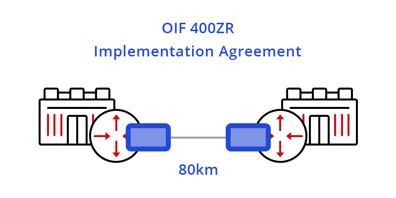
400G ZR coherent optical modules are compliant with the OIF-400ZR standard, ensuring industry-wide interoperability. They provide 400Gbps of optical bandwidth over a single optical wavelength using DWDM (dense wavelength division multiplexing) and higher-order modulation such as 16 QAM. Implemented predominantly in the QSFP-DD form factor, 400G ZR will serve the specific requirement for massively parallel data center interconnect of 400GbE with distances of 80-120km. To learn more about 400G transceivers: How Many 400G Transceiver Types Are in the Market?

Overview of 400G ZR+

ZR+ is a range of coherent pluggable solutions with line capacities up to 400Gbps and reaches well beyond 80km supporting various application requirements. The specific operational and performance requirements of different applications will determine what types of 400G ZR+ coherent plugs will be used in networks. Some applications will take advantage of interoperable, multi-vendor ecosystems defined by standards body or MSA specifications and others will rely on the maximum performance achievable in the constraints of a pluggable module package. Four categories of 400G ZR+ applications will be explained in the following part.

400G ZR & ZR+: Applications

400G ZR – Application Scenario

The arrival of 400G ZR modules has ushered in a new era of DWDM technology marked by open, standards based, and pluggable DWDM optics, enabling true IP-over-DWDM. 400G ZR is often applied for point-to-point DCI (up to 80km), making the task of interconnecting data centers as simple as connecting switches inside a data center (as shown below).

Figure 1: 400G ZR Applied in Single-span DCI

Four Primary Deployment Applications for 400G ZR+

Extended-reach P2P Packet

One definition of ZR+ is a straightforward extension of 400G ZR transcoded mappings of Ethernet with a higher performance FEC to support longer reaches. In this case, 400G ZR+ modules are narrowly defined as supporting a single-carrier 400Gbps optical line rate and transporting 400GbE, 2x 200GbE or 4x 100GbE client signals for point-to-point reaches (up to around 500km). This solution is specifically dedicated to packet transport applications and destined for router platforms.

Multi-span Metro OTN

Another definition of ZR+ is the inclusion of support for OTN, such as client mapping and multiplexing into FlexO interfaces. This coherent pluggable solution is intended to support the additional requirements of OTN networks, carry both Ethernet and OTN clients, and address transport in multi-span ROADM networks. This category of 400G ZR+ is required where demarcation is important to operators, and is destined primarily for multi-span metro ROADM networks.

Figure 2: 400G ZR+ Applied in Multi-span Metro OTN

Multi-span Metro Packet

The third definition of ZR+ is support for extended reach Ethernet or packet transcoded solution that is further optimized for critical performance such as latency. This 400G ZR+ coherent pluggable with high performance FEC and sophisticated coding algorithms supports the longest reach over 1000km multi-span metro packet transport.

Figure 3: 400G ZR+ Applied in Multi-span Metro Packet

Multi-span Metro Regional OTN

The fourth definition of ZR+ supports both Ethernet and OTN clients. This coherent pluggable also leverages high performance FEC and PCS, along with tunable optical filters and amplifiers for maximum reach. It supports a rich feature set of OTN network functions for deployment over both fixed and flex-grid line systems. This category of 400G ZR+ provides solutions with higher performance to address a much wider range of metro/regional packet networking requirements.

400G ZR & ZR+: What Makes Them Suitable for Longer-reach Transmission in Data Center?

Coherent Technology Adopted by 400G ZR & ZR+

Coherent technology uses the three degrees of freedom (amplitude, phase and polarization of light) to focus more data on the wave that is being transmitted. In this way, coherent optics can transport more data over a single fiber for greater distances using higher order modulation techniques, which results in better spectral efficiency. 400G ZR and ZR+ is a leap forward in the application of coherent technology. With higher-order modulation and DWDM unlocking high bandwidth, 400G ZR and ZR+ modules can reduce cost and complexity for high-level data center interconnects.

Importance of 400G ZR & ZR+

400G ZR and 400G ZR+ coherent pluggable optics take implementation challenges to the next level by adding some of the elements for high-performance solutions while pushing component design for low-power, pluggability, and modularity.

Conclusion

Although there are still many challenges to making 400G ZR and 400G ZR+ transceiver modules that fit into the small size and power budget of OSFP or QSFP-DD packages and also achieving interoperation as well the costs and volume targets. With 400Gbps high optical bandwidth and low power consumption, 400G ZR & ZR+ may very well be the new generation in longer-reach optical communications.

Original Source: 400G ZR & ZR+ – New Generation of Solutions for Longer-reach Optical Communications

What Is SWDM4 and 100G SWDM4 Transceiver?

Share

With the promotion of OM5 multimode fiber (MMF) and the large-scale deployment of 40G or 100G data center transmission network, SWDM technology has gradually entered people’s field of vision and has begun to be applied. Then, what is SWDM4? What is 100G SWDM4 transceiver? What are the advantages of them? Look at the text below to get all the answers.

What Is SWDM4?

To begin with, you should know what the SWDM is before knowing anything about SWDM4, right? Then, what is SWDM?

Actually, SWDM, whose whole full name is short wavelength division multiplex, is a new multi-vendor technology that promises to provide the lowest total cost solution for enterprise data centers upgrading to 40G and 100G Ethernet with the existing 10G duplex OM3/OM4 MMF infrastructure. What’s more, it can cost-effectively increase bandwidth density for new data center builds and extend the reach when used with OM5 wideband multimode fiber (WBMMF) as well. By the way, OM5 fiber also future-proofs the infrastructure for possible future 200G, 400G and 800G interfaces.

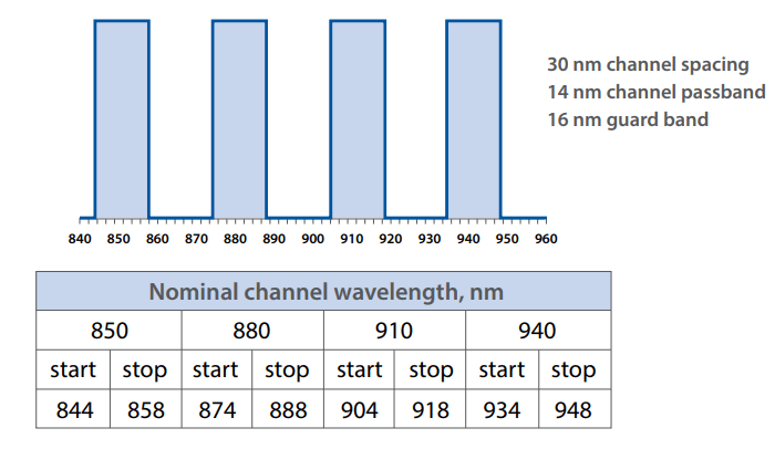
To upgrade data centers to 40G/100G Ethernet without changing the existing duplex MMF infrastructure being used for 10G Ethernet, pluggable optical transceivers with SWDM technology matters a lot. This approach consists of multiple vertical-cavity surface-emitting lasers (VCSELs) operating at different wavelengths in the 850nm window (where MMF is optimized). The four-wavelength implementation of SWDM is called SWDM4, and these four wavelengths (850, 880, 910 and 940 nm) are multiplexed/demultiplexed inside a transceiver module into a pair of MMFs (one fiber in each direction, i.e., a standard duplex interface). Each of the four wavelengths operates at either 10G or 25G, enabling the transmission of 40G (4 x 10G) or 100G (4 x 25G) Ethernet over existing duplex MMF, using standard LC connectors.

Four SWDM4 wavelengths defined by SWDM MSA

What is 100G SWDM4 Transceiver?

SWDM4 transceivers can deliver 40G and 100G connections in the same way a standard SFP+ transceiver connects, using duplex LC OM3 or OM4 cabling. Here, we will focus on the 100G connections. You may know something about 100G transceiver, then, what about 100G SWDM4 transceiver?

Actually, from the name, it is easy to tell that a 100G SWDM4 transceiver is a 100G transceiver featuring SWDM4 technology. It provides 100Gbps bandwidth over a standard duplex MMF, eliminating the need for expensive parallel MMF infrastructure. And it offers a seamless migration path from duplex 10G to 100G.

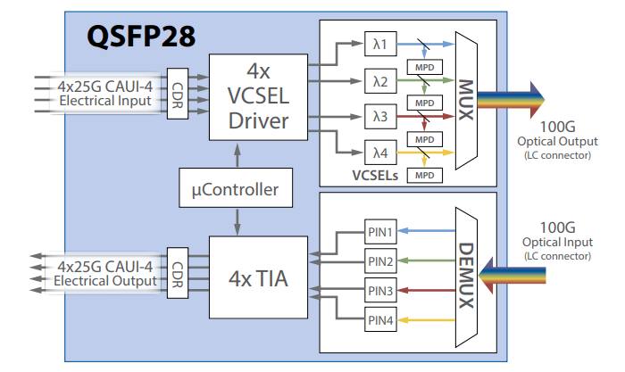
According to 100G SWDM4 MSA Technical Specifications, a 100G SWDM4 QSFP28 transceiver can be used for links up to 75m of OM3 fiber or up to 100m of OM4 fiber. The Tx port transmits 100G data over 4 x 25Gbps wavelengths, and the Rx port receives data over 4 x 25Gbps wavelengths. The wavelengths are in the “short wavelength” range (from 850nm to 940nm). Of course, you can use the advanced OM5 fiber operating only over two fibers to get better experience (up to 150m) with a higher price as well.

Block Diagram of a 100G SWDM4 QSFP28 Transceiver

Advantages of  a 100G SWDM4 Transceiver

Here are several benefits from using the SWDM4 in 100G environments with MMF:

  • Cost-Effective: It uses two fibers (duplex) instead of eight (SR4), enabling significant fiber infrastructure capex savings.
  • OM5 Supported: It supports links up to 150m over OM5 MMF with only two fibers.
  • Easy Migration to 100G: It enables seamless migrations from both 10G and 40G to 100G without major changes to the fiber infrastructure. It works on legacy OM3 or OM4 duplex MMF as well. The widely deployed 10G-SR, 40G-BiDi and 40G-Universal optics all operate over a single pair of MMF with regular LC termination. So does the 100G-SWDM4 transceiver. Therefore, users don’t need to change the existing cabling or re-terminate.
  • Familiar Tap Modules: It can be tapped using existing 1 x 2 Tap modules just like 10G-SR and 40G-Universal optics with no change or replacements, avoiding additional cost and complexity.

Conclusion

From all the above, you may have a general understanding of the three concepts: SWDM, SWDM4 and 100G SWDM4 transceiver. Given the advantages concerning above, SWDM technology and 100G SWDM4 transceivers might be dominant trends in the near future. Maybe you can keep an eye on it for future network construction. By the way, FS.COM offers a variety of 100G optical modules for you to choose from, such as PSM4, CWDM4, etc.

Related Articles:

Wideband Multimode Fiber: What to Expect From It?

Considerations for Buying Compatible Optical Transceiver

Share

When choosing compatible optical transceiver, nearly 90% of transceiver end users may worry about their quality and compatibility. As we know, the price of compatible optical module is usually much lower than original-brand transceiver. So, can compatible optical transceiver really perform well as the original one? What should I pay attention to when buying compatible optical module? This blog will give you some practical advice aimed to help you choose compatible optical transceiver with high compatibility and low cost.

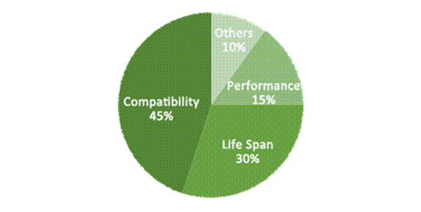
Main Concerns for Buying Compatible Optical Transceiver

  • Compatibility – The transceiver can’t be compatible with your original-brand switch.
  • Life Span – The quality of the transceiver is not reliable and the service life is short.
  • Poor performance – High latency etc.
  • Others – Refurbished modules, power consumption etc.

Compatible Optical Transceiver

How to Ensure Quality of Compatible Optical Transceiver?

1. Professional Testing Process

Make sure the compatible optical transceiver you buy is tested on relevant original-brand switch. For example, when you buy a Cisco compatible optical transceiver, make sure it’s tested on Cisco switches. Usually, the compatible optical transceiver that has been tested can always guarantee perfect performance in your network.

2. Guaranteed Warranty Policy

The shopping experience tells us that bad quality products usually have short-term warranties. If there’s something wrong with your products, the vendor won’t give you any maintenance and return service. Instead, if the warranty time is long such as lifetime warranty, the products’ quality may be more reliable and stable.

3. Reputable Brand Vendor

With strict quality control system and OEM experience for many years, reputable brand vendors can usually guarantee a reliable and stable connectivity for your high-speed fiber transmission system. All the raw materials they used are safe and the performance can be comparable with the original.

Reliable Compatible Optical Transceiver Structure Details

Besides the considerations mentioned above, knowing the structure details requirement of a good compatible optical transceiver may also help you a lot.

1. Premium Metal Housing

A good transceiver module is made of premium pluggable hard gold plating, which can ensure repeated plugging and unplugging. In addition, by strict control of the gold plating thickness, it can reach a superior quality and ensure excellent connection as well as reducing the working temperature.

premium-metal-housing

2. High-Quality Laser

The high-quality laser is with high sensitivity, low attenuation and high quality which ensure the perfect signal transmitting and receiving.

high-quality-laser

3. Advanced Chip

The advanced chip offers the high performance and low power consumption to the module solution which ensures the signal to be transmitted with high speed and stable performance.

advanced-chip

4. Perfect Combination

The combination of the gold-finger (conductive metal), chip and metal housing makes a perfect transceiver module.

perfect-combination

Conclusion

When you’re looking to upgrade your network, it makes sense to choose a compatible optical transceiver to help save cost. FS.COM, a professional manufacturer and supplier of compatible optical transceiver, may be your ideal choice. Each transceiver module from FS.COM is tested on the real working environment before shipping which ensures the reliable and stable performance. Besides, FS.COM offers a 60-day money-back return policy and a guaranteed warranty policy to ensure their transceivers’ quality. If you try to use them, you may like them.

Related Article: All About Compatibility: Third-Party vs. Brand Optics