Category Archives: 100G Transceiver

What Is SWDM4 and 100G SWDM4 Transceiver?

Share

With the promotion of OM5 multimode fiber (MMF) and the large-scale deployment of 40G or 100G data center transmission network, SWDM technology has gradually entered people’s field of vision and has begun to be applied. Then, what is SWDM4? What is 100G SWDM4 transceiver? What are the advantages of them? Look at the text below to get all the answers.

What Is SWDM4?

To begin with, you should know what the SWDM is before knowing anything about SWDM4, right? Then, what is SWDM?

Actually, SWDM, whose whole full name is short wavelength division multiplex, is a new multi-vendor technology that promises to provide the lowest total cost solution for enterprise data centers upgrading to 40G and 100G Ethernet with the existing 10G duplex OM3/OM4 MMF infrastructure. What’s more, it can cost-effectively increase bandwidth density for new data center builds and extend the reach when used with OM5 wideband multimode fiber (WBMMF) as well. By the way, OM5 fiber also future-proofs the infrastructure for possible future 200G, 400G and 800G interfaces.

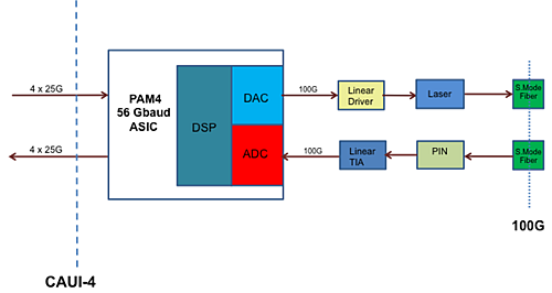
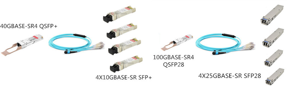
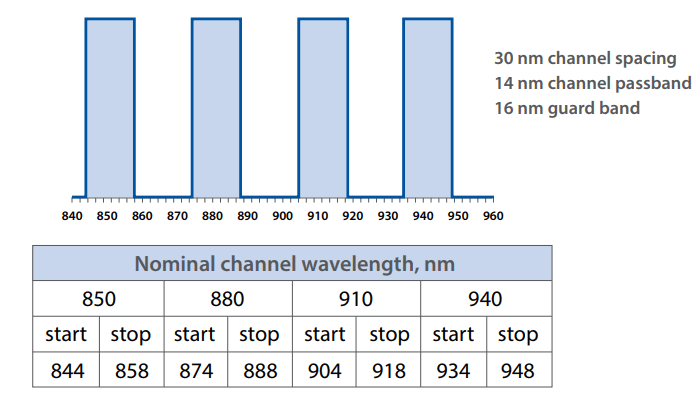
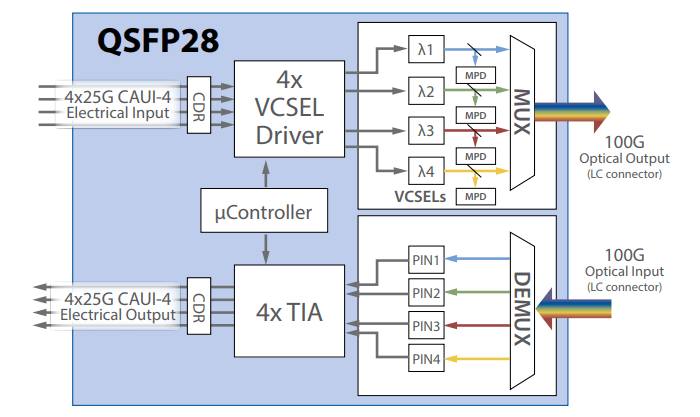
To upgrade data centers to 40G/100G Ethernet without changing the existing duplex MMF infrastructure being used for 10G Ethernet, pluggable optical transceivers with SWDM technology matters a lot. This approach consists of multiple vertical-cavity surface-emitting lasers (VCSELs) operating at different wavelengths in the 850nm window (where MMF is optimized). The four-wavelength implementation of SWDM is called SWDM4, and these four wavelengths (850, 880, 910 and 940 nm) are multiplexed/demultiplexed inside a transceiver module into a pair of MMFs (one fiber in each direction, i.e., a standard duplex interface). Each of the four wavelengths operates at either 10G or 25G, enabling the transmission of 40G (4 x 10G) or 100G (4 x 25G) Ethernet over existing duplex MMF, using standard LC connectors.

Four SWDM4 wavelengths defined by SWDM MSA

What is 100G SWDM4 Transceiver?

SWDM4 transceivers can deliver 40G and 100G connections in the same way a standard SFP+ transceiver connects, using duplex LC OM3 or OM4 cabling. Here, we will focus on the 100G connections. You may know something about 100G transceiver, then, what about 100G SWDM4 transceiver?

Actually, from the name, it is easy to tell that a 100G SWDM4 transceiver is a 100G transceiver featuring SWDM4 technology. It provides 100Gbps bandwidth over a standard duplex MMF, eliminating the need for expensive parallel MMF infrastructure. And it offers a seamless migration path from duplex 10G to 100G.

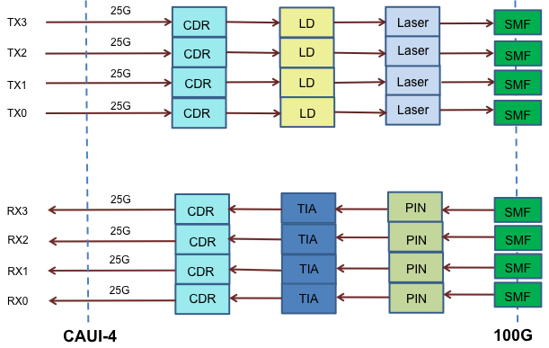
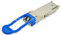
According to 100G SWDM4 MSA Technical Specifications, a 100G SWDM4 QSFP28 transceiver can be used for links up to 75m of OM3 fiber or up to 100m of OM4 fiber. The Tx port transmits 100G data over 4 x 25Gbps wavelengths, and the Rx port receives data over 4 x 25Gbps wavelengths. The wavelengths are in the “short wavelength” range (from 850nm to 940nm). Of course, you can use the advanced OM5 fiber operating only over two fibers to get better experience (up to 150m) with a higher price as well.

Block Diagram of a 100G SWDM4 QSFP28 Transceiver

Advantages of  a 100G SWDM4 Transceiver

Here are several benefits from using the SWDM4 in 100G environments with MMF:

  • Cost-Effective: It uses two fibers (duplex) instead of eight (SR4), enabling significant fiber infrastructure capex savings.
  • OM5 Supported: It supports links up to 150m over OM5 MMF with only two fibers.
  • Easy Migration to 100G: It enables seamless migrations from both 10G and 40G to 100G without major changes to the fiber infrastructure. It works on legacy OM3 or OM4 duplex MMF as well. The widely deployed 10G-SR, 40G-BiDi and 40G-Universal optics all operate over a single pair of MMF with regular LC termination. So does the 100G-SWDM4 transceiver. Therefore, users don’t need to change the existing cabling or re-terminate.
  • Familiar Tap Modules: It can be tapped using existing 1 x 2 Tap modules just like 10G-SR and 40G-Universal optics with no change or replacements, avoiding additional cost and complexity.

Conclusion

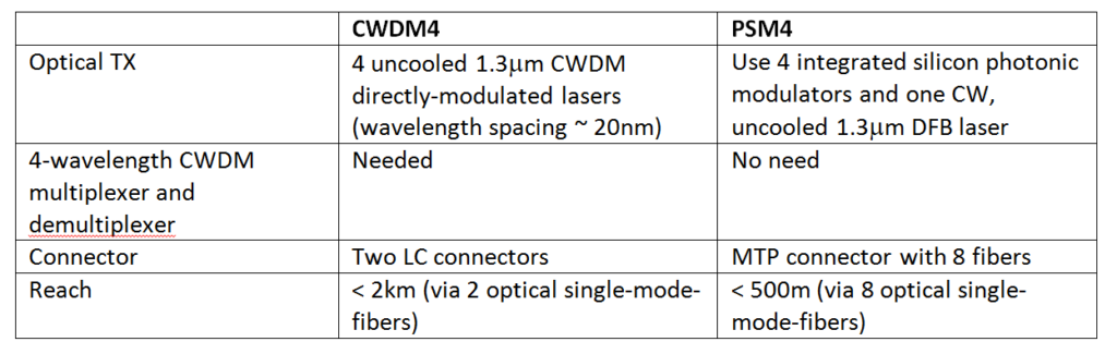
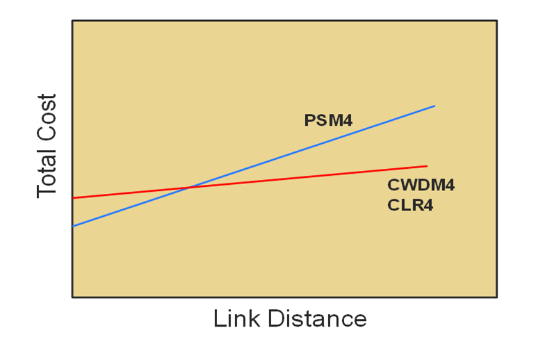
From all the above, you may have a general understanding of the three concepts: SWDM, SWDM4 and 100G SWDM4 transceiver. Given the advantages concerning above, SWDM technology and 100G SWDM4 transceivers might be dominant trends in the near future. Maybe you can keep an eye on it for future network construction. By the way, FS.COM offers a variety of 100G optical modules for you to choose from, such as PSM4, CWDM4, etc.

Related Articles:

Wideband Multimode Fiber: What to Expect From It?

100G PAM4 QSFP28 or Coherent CFP?

Share

The ever-increasing need for higher data rate in mobile data traffic, data centers and cloud services has pushed the access streams from 2.5Gb/s to 100Gb/s, and is demanding for 100Gb/s beyond without a stop. In today’s core network that has deployed 100G rates, there are QSFP28 optical transceivers including SR4, PSM4, CWDM4, LR4, ER4, etc., serving for a maximum 25km transmission distance. And there are 100G AOC, DAC and breakout cables generally for applications of tens of meters. 100G CFP/CFP2 modules including SR10, LR4 and ER4 support transmission distances of 150m to 40km. Until recent years, the telecom service providers are adopting new 100G DWDM technologies in their high capacity and long distance backbone applications. Coherent 100G DWDM transceivers are the first to be deployed for 100G long-haul applications, and then new technologies like PAM4 (Pulse Amplitude Modulation) are developed to meet lengths requirements for 100G metro network. This post is to discuss the issues on coherent and 100G PAM4 DWDM transceivers.

Overview on 100G DWDM Transceivers

In the past few years, the adoption of 100G DWDM technologies is mainly focused on coherent DWDM optical transceivers, including CFP and CFP2. Until the year 2016, Inphi (a specialist in this area) offers pluggable 100G PAM4 QSFP28 DWDM transceivers to support 80km data center interconnect (DCI). The alternative for 100G DWDM coherent transceiver is given much attention. Besides, this new option for 100G DWDM transceiver also arouses hot discussion on which to choose. Knowing the characteristics and suited applications of them could help in selection.

100G PAM4 QSFP28 and Coherent CFP/CFP2

There are significant differences between QSFP28 PAM4 transceivers and coherent CFP/CFP2 transceivers, but they also have some relations in 100G applications. Contents below will go to details of these optical modules.

QSFP28 PAM4

Before the announcement of PAM4, binary NRZ (non-return to zero) modulation format is used for 40G and 100G long-haul transmission systems. PAM4 has four distinct levels to encode two bits of data, essentially doubling the bandwidth of a connection. Currently the single-wavelength PAM4 modulation scheme is considered the most cost-effective, efficient enabler of 100G and beyond in the data center. The 100G DWDM transceiver utilizing PAM4 signaling is in QSFP28 form factor. The advantage is that the customers who want to build an embedded DWDM network can use this transceiver directly in the switch. On this side, it is simple and cost-effective solution. But there are some prerequisites: it needs amplification to get out of the blocks and dispersion compensation to go beyond 5-6km. Therefore, a separate DWDM multiplexer with an amplification system and dispersion compensation is required to connect data canters together.

single wavelength 100G PAM4

In another case, if the QSFP28 PAM4 module is added to an existing DWDM network, it must be a network already having right dispersion compensation modules (DCMs) and amplification system in place; if it is not, changes are required when QSFP28 PAM4 is later added.

Coherent CFP

CFP digital coherent optics (DCO) have a high speed digital signal processing (DSP) chip built in. They do not require separate DCMs. This is what makes CFP different from QSFP28. Instead, they have electronic dispersion compensation built in. Although the built-in DSP requires more power and adds cost in components, it releases the switch vendors from adding DSPs to their equipment. Coherent CFPs enables transmission distance of more than 1000km between sites.

CFP2 analog coherent optic (ACO) is half the width of the CFP. Existing CFP2 coherent DWDM optical transceivers are analog and require a separate DSP on the host board to take the full advantages of the coherent features. So it is suited for switch vendors who have fitted such a DSP, but it adds additional cost and power consumption on the main board.

CFP2 digital coherent optic (DCO), expected to be released in the coming two years, is more optimized than CFP2 ACO in that it has built-in DSP. This component will open up to all switch vendors using CFP2 without DSP. With different coherent CFPs optional, customers can pay only for what they need when they need it.

100G PAM4 QSFP28 or Coherent CFP?

This really should depend on the applications. According to ACG research (an analyst and consulting firm that focuses on the service providers’ networking and the telecom industry), the 100G PAM4 solution and coherent DWDM solution, together with IEEE802.3ba, cover different portions of the optical fiber reach in the data center interconnect. So when deploying a long distance 100G DWDM network with DWDM transceivers, the required transmission distance and available equipment should be taken into consideration when choosing a suitable pluggable module.

IEEE, PAM4, OIF coherent optical reaches

Conclusion

Using pluggable transceivers for embedded DWDM, where the DWDM functionality is in the transceiver and not a separate DWDM converter platform, offers the ultimate solution in terms of cost and simplicity. Both 100G PAM4 QSFP28 and coherent CFP/CFP2 are all suited to this approach. They can be used for embedded DWDM networking or as part of an existing DWDM installation. They all enable the advantages of pluggable modules: simple installation, easy spares handling, lower cost of ownership and quick return on invest.

Related Article: 100G Metro Network Technology Explained

Related Article: CFP Transceiver Module Overview: CFP, CFP2, CFP4 & CFP8

Can I Use the QSFP+ Optics on QSFP28 Port?

Share

100G Ethernet will have a larger share of network equipment market in 2017, according to Infonetics Research. But we can’t neglect the fact that 100G technology and relevant optics are still under development. Users who plan to layout 100G network for long-hual infrastructures usually met some problems. For example, currently, the qsfp28 optics on the market can only support up to 10 km (QSFP28 100GBASE-LR4) with WDM technology, which means you have to buy the extra expensive WDM devices. For applications beyond 10km, QSFP28 optical transceivers cannot reach it. Therefore, users have to use 40G QSFP+ optics on 100G switches. But here comes a problem, can I use the QSFP+ optics on the QSFP28 port of the 100G switch? If this is okay, can I use the QSFP28 modules on the QSFP+ port? This article discusses the feasibility of this solution and provides a foundational guidance of how to configure the 100G switches.

For Most Switches, QSFP+ Can Be Used on QSFP28 Port

As we all know that QSFP28 transceivers have the same form factor as the QSFP optical transceiver. The former has just 4 electrical lanes that can be used as a 4x10GbE, 4x25GbE, while the latter supports 40G ( 4x10G). So from all of this information, a QSFP28 module breaks out into either 4x25G or 4x10G lanes, which depends on the transceiver used. This is the same case with the SFP28 transceivers that accept SFP+ transceivers and run at the lower 10G speed.

QSFP can work on the QSFP28 ports

A 100G QSFP28 port can generally take either a QSFP+ or QSFP28 optics. If the QSFP28 optics support 25G lanes, then it can operate 4x25G breakout, 2x50G breakout or 1x100G (no breakout). The QSFP+ optic supports 10G lanes, so it can run 4x10GE or 1x40GE. If you use the QSFP transceivers in QSFP28 port, keep in mind that you have both single-mode and multimode (SR/LR) optical transceivers and twinax/AOC options that are available.

In all Cases, QSFP28 Optics Cannot Be Used on QSFP+ Port

SFP+ can’t auto-negotiate to support SFP module, similarly QSFP28 modules can not be used on the QSFP port, either. There is the rule about mixing optical transceivers with different speed—it basically comes down to the optic and the port, vice versa. Both ends of the two modules have to match and form factor needs to match as well. Additionally, port speed needs to be equal or greater than the optic used.

How to Configure 100G Switch?

For those who are not familiar with how to do the port configuration, you can have a look at the following part.

  • How do you change 100G QSFP ports to support QSFP+ 40GbE transceivers?

Configure the desired speed as 40G:
(config)# interface Ethernet1/1
(config-if-Et1/1)# speed forced 40gfull

  • How do you change 100G QSFP ports to support 4x10GbE mode using a QSFP+ transceiver?

Configure the desired speed as 10G:
(config)# interface Ethernet1/1 – 4
(config-if-Et1/1-4)# speed forced 10000full

  • How do you change 100G QSFP ports from 100GbE mode to 4x25G mode?

Configure the desired speed as 25G:
(config)# interface Ethernet1/1 – 4
(config-if-Et1/1-4)# speed forced 25gfull

  • How do you change 100G QSFP ports back to the default mode?

Configure the port to default mode:
(config)# interface Ethernet1/1-4
(config-if-Et1/1)# no speed

Note that if you have no experience in port configuration, it is advisable for you to consult your switch vendor in advance.

Conclusion

To sum up, QSFP+ modules can be used on the QSFP28 ports, but QSFP28 transceivers cannot transmit 100Gbps on the QSFP+ port. When using the QSFP optics on the QSFP28 port, don’t forget to configure your switch (follow the above instructions). To make sure the smooth network transmission, you need to ensure the connectors on both ends are the same and no manufacturer compatibility issue exists.

Simplify the Implementation of High Density 100G CXP

Share

Data center bandwidth demands continue to grow, requiring higher capacity and throughput. The 100G/120G Ethernet is no longer new in data center optic market, but it’s still a complex act to efficiently and effectively upgrade existing 10G/40G architectures to these higher data rates, especially in a space-constrained application. In order to explore the approaches of smooth migration to high density 100G/120G network, this post will take multimode 100G/120G CXP module as example, and illustrate some simplified scenarios when upgrading to these higher data rates.

Overview on 120G CXP Module

High density 100G CXP is very popular in the implementations up to 100Gbps for saving-space. This deployment can then leverage the 10G-per-lane channels to distribute the 10G data anywhere in the data center. 100G CXP module is designed to connect with an MTP/MPO-24 connector, which can be divided to 10x10G or 12x10G transceiver pairs. For 120G CXP, it is also possible to separate the signals into three QSFP+ transceivers, and then to three groups of 4x10G transceivers by using an 8 fibers MTP/MPO to LC breakout module or cable.

Direct Connectivity for Two CXPs

For two 100GBASE-SR10 modules, direct link can be easily made via 100G MPO cable. For connecting two 120G CXPs, a cost-effective 24 fibers MPO trunk can also work well. Here uses an 24 fibers MPO (female) to MPO (female) OM4 polarity B trunk cable.

direct link for two 100G/120G CXP modules

Figure 1: direct link for two 100G CXP modules.

Connectivity Methods for 120G CXP and SFP+/QSFP+

In this part, the scenarios applied for 100G to 10G connection, and 120G to 40G or 10G connection will be explained.

100G to 10G

Figure 2 shows a direct link for one 100G CFP module and ten 10G SFP+ modules. By using the 24 fibers MPO to LC duplex harness cable, the whole 100G from the CFP transceiver is connected to ten SFP+ transceivers (two LC duplex legs are not used in this link). The fanout legs are available to be the same length or staggered type, so as to meet different applications.

direct link for a 100G CFP to 10x10G SFP+s

Figure 2: direct link for a 100G CFP to 10x10G SFP+s.

In figure 3, the interconnect for CFP and SFP+ transceivers is more flexible than the direct link. Here the 160 fibers MTP/MPO (male) breakout patch panel allows connectivity to any duplex path reachable by the patch panel. This method offers ultimate flexibility in allowing connectivity to any row, rack or shelf. Moreover, this breakout module can support up to eight groups of this 100G to 10x10G transmission. In such a high density link, it is suggested to use HD patch cables or LC uniboot patch cables to enable quicker and better cable management.

interconnect solution for 100G CFP to 10x10G SFP+s

Figure 3: interconnect solution for 100G CFP to 10x10G SFP+s.

120G to 10G and 40G

When directly connecting one 120G CXP to twelve 10G SFP+ transceivers, a 24 fibers MTP-24 to 12 LC harness cables can do the job well. Here we use a customized high density bend insensitive female MTP-24 to 12 LC duplex OM4 breakout cable.

 direct link for 120G to 12x10G transceivers

Figure 4: direct link for 120G to 12x10G transceivers.

An option for breaking out a 120G CXP to three 40G QSFP+s is to use the 1×3 MTP/MPO conversion harness cable. Figure 5 illustrates implementation of a 1×24 strand MTP to 3×8 strand MTP conversion harness cable. Like the 12x10G segregation mentioned above, once split, the 3×8-fiber QSFP+ channels can be distributed through patch panels and 12-fiber based trunking to any area of the data center.

hybrid link for 120G CXP to 40G QSFP+s and 10G SFP+s

Figure 5: hybrid link for 120G CXP to 40G QSFP+s and 10G SFP+s.

Conclusion

This article has illustrated some simplified implementation examples of 100G CXP modules. 24 fibers MTP/MPO trunk cable are suited for connecting two CXP modules. Breakout cables can achieve quick connection for CXP and QSFP+ or SFP+ optics, but when flexible patching is needed in the link, it would be better to adopt breakout patch panel. If you need 100G optics, FS.COM can offer you fully tested compatible 100GBASE-SR10, 100G SR4, 100GBASE-LR4 and 100GBASE-ER4 transceivers, etc.

100G CFP Modules Power and Connectors Comparison

Share

In today’s market, only several vendors can provide 100G CFP modules, such as Cisco, Juniper, Brocade and Huawei. In this blog, I will compare the Cisco CFP modules and the Juniper CFP modules, and analyze the power and connectors of these modules.

100GBASE-SR10 CFP Modules
Both Cisco CFP-100G-SR10 and Juniper CFP-100GBASE-SR10 CFP module supports link lengths of 100 meters and 150 meters respectively on laser-optimized OM3 and OM4 multifiber cables. It primarily enables high-bandwidth 100-gigabit links over 24-fiber ribbon cables terminated with MPO/MTP-24 connectors. It can also be used in 10 x 10 Gigabit Ethernet mode along with ribbon to duplex fiber breakout cables for connectivity to ten 10GBASE-SR optical interfaces.

100GBASE-SR10 CFP Modules

100GBASE-LR4 CFP Modules
Both Cisco CFP-100G-LR4 and Juniper CFP-GEN2-100GBASE-LR4 CFP module supports a link length of 10 kilometers on standard duplex single-mode fiber (SMF, G.652). However, the connectors of Cisco CFP-100G-LR4 are duplex SC, and the connectors of Juniper CFP-GEN2-100GBASE-LR4 are duplex LC. 100 Gigabit Ethernet signal is carried over four wavelengths. Multiplexing and demultiplexing of the four wavelengths are managed within the device.

100GBASE-LR4 CFP Modules

100GBASE-ER4 CFP Modules
Both Cisco CFP-100G-ER4 and Juniper CFP-GEN2-CGE-ER4 CFP module can support link lengths up to 40 kilometers on standard duplex single-mode fiber (SMF, G.652). Like the 100GBASE-LR4 CFP modules, the connectors of Cisco CFP-100G-ER4 are duplex SC, and the connectors of Juniper CFP-GEN2-CGE-ER4 are duplex LC. Multiplexing and demultiplexing of the four wavelengths are managed within the device. The 100GBASE-ER4 CFP module meets the IEEE 802.3ba requirements for 100GBASE-ER4 performance and also supports Digital Optical Monitoring (DOM) of the transmit-and-receive optical signal levels.

Tx/Rx Power of Cisco and Juniper 100G CFP Modules
Minimum and maximum Tx/Rx Power of Cisco and Juniper 100G CFP Modules are displayed in the table below. We can see that there is no significant difference between Tx/Rx Power of Cisco and Juniper CFP modules.

P/N Connector Transmit Power Receive Power Wavelength
Cisco CFP-100G-SR10 OM3 100 m; OM4 150 m 24F-MPO/MTP min: -7.6 dBm
ma: -1.0 dBm
min: -9.5 dBm
max: 2.4 dBm
Ten lanes, 840 to 850 nm
Juniper CFP-100GBASE-SR10 OM3 100 m; OM4 150 m 24F-MPO/MTP min: -7.6 dBm
max: 2.4 dBm
min: -9.5 dBm
max: 2.4 dBm
840 through 860 nm
Cisco CFP-100G-LR4 10km duplpx SC min: -4.3 dBm
max: 4.5 dBm
min: -10.6 dBm
max: 4.5 dBm
Four lanes, 1295.6 nm, 1300.1 nm, 1304.6 nm, and 1309.1 nm
Juniper CFP-GEN2-100GBASE-LR4 10km duplpx LC min: -4.3 dBm
max: 4.5 dBm
min: -10.5 dBm
max: 4.5 dBm
1294.53 through 1296.59 nm
1299.02 through 1301.09 nm
1303.54 through 1305.63 nm
1308.09 through 1310.19 nm
Cisco CFP-100G-ER4 40km duplpx SC min: -2.9 dBm
max: 2.9 dBm
min: –20.9 dBm
max: 4.5 dBm
Same as CFP-100G-LR4
Juniper CFP-GEN2-CGE-ER4 40km duplpx LC min: -2.9 dBm
max: 2.9 dBm
min: –20.9 dBm
max: 4.5 dBm
Same as CFP-GEN2-100GBASE-LR4

As a leading and professional manufacturer and supplier of fiber optic subsystems and components. Fiberstore offers various 100G CFP modules which are ideal solutions for your 100GbE network. Our 100G transceivers are with high compatibility that can be compatible with many major brands. For more information, please contact us over sales@fs.com.

Related Article: CFP Transceiver Module Overview: CFP, CFP2, CFP4 & CFP8

S6100-ON vs Z9100-ON: Which Dell 100GbE Switch to Choose?

Share

Whether you recognize it or not, 100GbE is right here, right now. As the industry’s first multi-rate 100GbE 1U Ethernet switch, Dell’s Z9100-ON sets a high standard for the competition to follow. Soon afterwards Dell launched 2U 100GbE switches S6100-ON. These two Dell 100GbE switches support for a wide range of port speeds allows early adopters to move to 25GbE now and upgrade to 40GbE, 50GbE or 100GbE when the price is right. Which one did you deploy now? And why did you make the choice?

Dell Z9100-ON 100GbE Switches
The Dell Networking Z9100-ON is a 100GbE top-of rack (ToR) fixed switch purpose-built for applications in high-performance data center and computing environments. Z9100-ON 100GbE switch has 32 fixed 100GbE QSFP28 ports and a couple of 10GbE SFP+ ports to one side. This also allows for up to 64 ports of 50GbE, 32 ports of 40GbE, 128 ports of 25GbE or 128+2 ports of 10GbE switching all within the same module. Dell has thoughtfully provided these to allow you to connect legacy servers or switches without wasting a 100GbE port.

Dell 100GbE Switch Z9100-ON
Dell S6100-ON 100GbE Switches
Dell Networking S6100-ON Multi-rate Fabric Switch is a customizable fixed form factor 100GbE switch with 4 bays and 3 unique modules. It allows customers to mix and match modules delivering greater flexibility and choice than anything on the market today for this technology.
1) 16 ports of 40GbE. With 4 of these modules, customers can have up to 64ports of 40GbE in just 2RU!
2) 8 ports of QSFP28. This allows for up to 8 ports of 100GbE, 16 ports of 40 or 50GbE, or 32 ports of 10 or 25GbE switching all within the same module.
3) 4 ports of QSFP28 and 4 ports of CXP. The CXP ports allow for interconnects with legacy 100GbE in customer’s existing data centers as well as 4 ports of the newer/lower cost QSFP28.

Dell 100GbE Switch S6100-ON

S6100-ON vs Z9100-ON
If you want to build 100G network, both S6100-ON and Z9100-ON 100GbE switches can meet your requirement. Z9100-ON has fixed 100G QSFP28 ports and 10G SFP+ ports, and S6100-ON has fixed 100G QSFP28 ports, 100G CXP ports and 40G QSFP28 ports. Therefore, compared to Z9100-ON 100GbE switch, S6100-ON seems has more flexibility. And the S6100-ON price is higher than Z9100-ON. You can choose the right one for your specific requirements. To better power up your Dell S6100-ON or Z9100-ON 100GbE switches, you may need some good quality but cost-effectiive 100G optics and cables. FS.COM (Fiberstore) provides Dell QSFP28-100G-SR4 transceivers at 400 dollars and QSFP-100G-CWDM4 transceivers at 1350 dollars. And all these two transceiver modules are in stock now for same-day shipping. Besides the optics, Dell 100GbE QSFP28 to QSFP28 cables and 4x25GbE QSFP28 to SFP28 cables are also offered in Fiberstore for your option.

Related articles:

OpenFlow Switch: What Is It and How Does it Work?

Optics Solutions for FS.COM 100G Switches

100G Optical Transceivers Links: PSM4 vs CWDM4

Share

In the past few years, 100G optical transceivers are become more popular and widely used than before. The most common 100G optical transceivers we use today are CFP, CFP2, CFP4 and QSFP28, especially the QSFP28. Besides 100G optical transceivers links (-SR10, SR4, -LR4) defined by IEEE standard, Multi-Source Agreement (MSA) also defines two 100G optical transceivers links: PSM4 and CWDM4. Both architectures take the 100GE signal and carry it over 4 separate channels. So, what’s the difference between them? PSM4 vs CWDM4–difference between them will be introduced in this blog.

PSM4
The 100G PSM4 Specification defines requirements for a point-to-point 100 Gb/s link over eight single mode fibers (4 transmit and 4 receive) up to at least 500 m, each transmitting at 25Gbps. Four identical and independent lanes are used for each signal direction (as shown in figure below). Therefore, two transceivers communicate usually over 8-fiber MTP/MPO single mode patch cords. PSM4 is limited to 500 m, and it is usually used in 100G QSFP28 optical transceivers.

100G Optical Transceivers Links PSM4

CWDM4
Similar to PSM4, CWDM4 also uses 4 x 25 Gbps to achieve 100 Gbps. But unlike it, CWDM4 uses an optical multiplexer and de-multiplexer to reduce the number of fibers to 2 (as shown in figure below). Therefore, we only need to use a duplex single mode fibers to connect two 100G CWDM4 optical transceivers modules. CWDM4 is limited to 2 km. At present, CWDM4 links are used in both 100G CFP4 or the QSFP28 optical transceivers.

100G Optical Transceivers Links CWDM4

100G Optical Transceivers Links: PSM4 vs CWDM4
A summary table comparing the key differences between the two 100G transceivers is shown below. From an optical transceiver module structure viewpoint, PSM4 can be more cost effective because it uses a single uncooled CW laser which splits its output power into four integrated silicon modulators. However, from an infrastructure viewpoint, this transceiver would be more expensive when the link distance is long, mainly due to the fact that it uses 8 optical single-mode-fibers while CWDM4 uses only 2 optical single-mode-fibers.

100G Optical Transceivers Links PSM4 vs CWDM4
When considering the above two factors, a total cost comparison can be qualitatively shown in the figure below. As can be seen in the figure, PSM4 starts with a lower cost due to its lower transceiver cost, but as the link distance increases, its total cost climbs up very fast due to the fact that it uses 8 optical fibers.

100G links PSM4 vs CWDM4

Conclusion
Different companies have different opinions on what the link distance is at the crossing point, and what the transceiver cost difference is at zero distance. But based on the specifications of PSM4 MSA, the technology has to be limited to 500 meters, which can actually cover the majority of today’s data center needs. FS.COM provides both 100G PSM4 QSFP28 ($ 750.00) and 100G CWDM4 QSFP28 ($ 1350.00) optical transceivers for your options.

Related Article: https://www.cables-solutions.com/100g-qsfp28-pam4-coherent-cfp.html

QSFP+ and QSFP28 Transceivers Cabling Solutions

Share

The short range 40-Gigabit Ethernet QSFP+ and 100-Gigabit Ethernet QSFP28 transceivers that are widely used in today’s data center use 12-fiber patch cables with female MPO connectors. The fiber can be either OM3 or OM4. The long range QSFP+ and QSFP28 transceiver use single-mode fiber patch cables with duplex LC connectors. This article may introduce the cabling solutions for QSFP+ and QSFP28 transceiver to you.

QSFP+ and QSFP28 Transceiver Types
In terms of 40G QSFP+ transceivers, from short range to long range, they are available in 5 common types. The minimum transmission distance is 100m, and the max transmission distance is 40km. 100G QSFP28 transceivers are commonly avaiable in 100GBASE-SR4 and 100GBASE-LR4 two types. Detailed QSFP+ and QSFP28 transceiver specifications are displayed in following tables.

Transceiver Type Interface Standard Connector Type Fiber Type
QSFP+ 40GBASE-SR4 Female MTP/MPO, key up 12-fiber multi-mode fiber (MMF) (OM3 or OM4)
QSFP+ 40GBASE-PLRL4 Female MTP/MPO, key up 12-fiber single-mode fiber (SMF) 1km
QSFP+ 40GBASE-PLR4 Female MTP/MPO, key up 12-fiber SMF 10km
QSFP+ 40GBASE-LR4 LC duplex SMF 10km
QSFP+ 40GBASE-ER4 LC duplex SMF 40km
QSFP28 100GBASE-SR4 Female MTP/MPO, key up 12-fiber MMF (OM3 or OM4)
QSFP28 100GBASE-LR4 LC duplex SMF 10km

12-Fiber Patch Cables with MTP Connectors
12-fiber patch cables with MTP connectors can be used to connect two transceivers of the same type—40GBASE-SR4-to-40GBASESR4 or 100GBASE-SR4-to-100GBASE-SR4. You can also connect 4x10GBASE-LR transceivers such as 40GBASE-PLRL4 and 40GBASE-PLR4 using patch cables—4x10GBASE-LR-to-4x10GBASE-LR—instead of breaking the signal out into four separate signals. Ensure that you order cables with the correct polarity. The MTP connectors on the 12-fiber cables should be key up (sometimes referred to as latch up, Type B, or Method B). If you are using patch panels between two QSFP+ or QSFP28 transceivers, ensure that the proper polarity is maintained through the cable plant.

12-Fiber MTP Patch Cables

12-Fiber MPO Patch Cables

12-Fiber Breakout Cables with MTP-LC Duplex Connectors
12-fiber breakout cables with MTP-LC duplex connectors can be used to connect a 4x10GBASE-LR or 4x10GBASE-SR transceiver to four separate 10GBASE-LR or 10GBASE-SR SFP+ transceivers. The breakout cable is constructed out of a 12-ribbon fiber-optic cable. The breakout cable splits from a single cable with an MTP connector on one end, into 4 cable pairs with 4 LC duplex connectors on the opposite end.

40G QSFP+ and 100G QSFP28 transceivers solution

40G to 4×10G

LC Duplex Patch Cables
Single-mode patch cables with LC duplex connectors can be used to connect two transceivers of the same type—40GBASE-LR4-to-40GBASE-LR4 or 100GBASE-LR4-to100GBASE-LR4. The SMF patch cable is one fiber pair with two LC duplex connectors at opposite ends.

LC Duplex Patch Cables

Related Article: Can I Use the QSFP+ Optics on QSFP28 Port?

25G SFP28 Cable: The Most Economical Option for ToR Server Connection

Share

Have you ever heard of 25G SFP28 cable? It is said to be regarded as the most economical option for ToR server connection. Continue to read and get more details.

What’s 25G SFP28 Cable?

As you may know that 25 Gigabit Ethernet is proposed standard for Ethernet connectivity in a data center environment, developed by IEEE 802.3 task force P802.3by. The IEEE 802.3bj standard then uses technology defined for 100 Gigabit Ethernet implemented as four 25-Gbit/s lanes. These standards define:

  • a single-lane 25 Gbit/s 25GBASE-KR PHY for printed circuit backplanes
  • a single-lane 25 Gbit/s 25GBASE-CR-S PHY for 3 m twin-ax cables (in-rack)
  • a single-lane 25 Gbit/s 25GBASE-CR-L PHY for 5 m twin-ax cables (inter-rack)
  • a single-lane 25 Gbit/s 25GBASE-SR PHY for 100 m OM4 or 70 m OM3 multi-mode optical fiber

According to the above standards, the IEEE CFI is now focused on the SFP28 and QSFP28 direct attach copper twin-ax cables (DACs). SFP28 DAC refers to the 25G DAC cable using the SFP+ form factor, and QSFP28 DAC refers to the 100G DAC cable using the QSFP+ form factor. The maximum transmission distance of these cables is 5 meters.

There are two SFP28 cable types: 25G SFP28 to SFP28 DAC and 100G QSFP28 to four SFP28 breakout DAC. The SFP28 to SFP28 passive copper cable is a high speed, cost-effective 25Gbp/s Ethernet connectivity solution designed to meet the growing needs for higher bandwidth in data centers. The QSFP28 to four SFP28 breakout DAC is used to connect 100G switches to four 25 Gigabit in cabinet or adjacent cabinet servers. Compared to 40G using four 10G lanes and 100G using 10 10G lanes, the 25G SFP28 DAC provides the low-cost copper server connection for Top of Rack (ToR) switches.

To more directly illustrate effectiveness of SFP28 to SFP28 DAC cable and QSFP28 to four SFP28 breakout DAC cable, let’s see a series of pictures displayed below:

Existing 10G Topology
Today’s volume topology for web-scale data centers

  • 48 servers/ToR
  • 3:1 oversubscription
  • Uses low-cost, thin 4-wire SFP+ DAC cable

sfp+ to sfp+ DAC

40G Topology
High-performance, low volume topology

  • Uses bulkier 16-wire QSFP+ DAC cable
  • Max. 24 servers/ToR with 3:1 oversubscription
  • Will transition to 100G

qsfp+ to qsfp+ dac

25G Direct Connect
Same topology as 10G

  • 48 servers/ToR
  • 3:1 oversubscription w/ 100G uplinks, non-blocking w/ 400G
  • Uses 4-wire SFP28 DAC cable

sfp28 to sfp28 dac

Existing 4x10G Topology
Commonly used topology in web-scale data centers

  • Permits non-blocking 10G mesh
  • 40G ports used as 4x10G with QSFP+ to SFP+ breakout cable
  • Same server network interface card (NIC) as 10G

qsfp+ to 4 sfp+ dac

4x25G Breakout
Same topology as 4x10G

  • Permits non-blocking 25G mesh
  • 100G ports used as 4x25G with QSFP28 to SFP28 break-out cable
  • Same server network interface card (NIC) as 25G direct connect

qsfp28 to 4 sfp28 dac

High Density 25G
Increased port switch port density

  • 64 servers in non-blocking architecture
  • 96 servers in a 3:1 oversubscription
  • 24-port 400G ToR
  • 192 servers in non-blocking architecture

100G qsfp28 to 4 sfp28 dac

Related articles:

Taking an In-depth Look at 25G SFP28

25G Vs. 40G Ethernet: Who Is the Winner?

How Far Can 25G Ethernet Go?

The Changing Network Architecture in 25G/100G Data Center

100G Optical Transceivers Will Be More Popular in 2016

Share

According to a newly published report by Dell’Oro Group, the worldwide service provider core router market is expected to reach $3.4 billion in revenue in 2020 as 100G port shipments spur growth. There is a significant increase in deployments of 100G ports, driven by the continuous increase in IP traffic as well as the availability of higher capacity line cards in 2015. Besides, pricing declined significantly in 2015 for 100G as there was a mix shift in the types of routers on which 100G ports were installed. Furthermore, the availability of advanced optics in CFP2 and CPAK has pushed down pricing on 100G. Therefore, we expect 100G optical transceivers will be more and more popular in 2016.

100G Optical Transceiver Modules: from CFP to QSFP28
At present market, the 100G optical transceiver module include CXP, CFP, CFP2, CPAK, CFP4 and QSFP28. Among them, QSFP28 demonstrates its great superiority and will lead to denser optics and further price reductions. The QSFP28 increases front-panel density by 250% over QSFP+. The increase in panel density is even more dramatic when compared to some of the other 100G transceiver module: 450% versus the CFP2 and 360% versus the CPAK. In addition, the surge of QSFP28 shipments will be one of the factors to change the market from 40G to 100G, according to the report of IHS. QSFP28 is fast becoming the universal data center form factor.

100G Optical Transceiver Module

100G Optical Transceiver Module Is Much Cheaper Than Before
The cost for transceiver modules which keep adding up over time is one of the main considerations of the whole projects. In other word, the cost of the devices and components may influence the enthusiasm of network upgrade. But, in 2016, the 100G transceivers will be more affordable. On one hand, the cheap 100G silicon reaches production and the technology become mature. On the other hand, the adoption of widespread use of the 100G devices, and the vast increases in Internet traffic are core to change in the communications infrastructure markets. This reduction in pricing will lead to 100 GE selling at a price per bit transmitted below that of 10 GE in the 2018 time frame.

100G Optical Transceiver Module Is More Widely Used
Previously, 100G was primarily installed on high-end core routers and now more are being installed on relatively lower-priced edge routers, which pricing declined significantly reduces the price of 100G optical transceiver. In 2016, the global data center construction market will keep growing which means that the 100G optics application will be more wider. Geographically, North America, Europe and Asia-Pacific (mainly China) are the main market for 100G transceiver with their increasing demand for deployment of 100G equipment.

Fiberstore 100G Optical transceiver Solution
In 2015, FS.COM constantly improves the product line of fiber optic transceivers. For 100G optics, we introduced the 100GBASE-LR4 CFP2 and CFP4 modules as well as the 100GBASE-SR4 and 100GBASE-LR4 QSFP28 modules. With our serious cost control, the prices of all our 100G optics are much more affordable than the similar products in the market. Furthermore, with the mature coding technology, they can be compatible with many major brands.

FS Part Number Product Photo Description
CFP-LR4-100G CFP-LR4-100G 100GBASE-LR4 CFP 1310nm 10km Transceiver for SMF
CFP2-LR4-100G CFP2-LR4-100G 100GBASE-LR4 CFP2 1310nm 10km Transceiver for SMF
CFP4-LR4-100G CFP4-LR4-100G 100GBASE-LR4 CFP4 1310nm 10km Transceiver for SMF
QSFP28-SR4-100G QSFP28-SR4-100G 100GBASE-SR4 QSFP28 850nm 100m Transceiver for MMF
QSFP28-LR4-100G QSFP28-LR4-100G 100GBASE-LR4 QSFP28 1310nm 10km Transceiver for SMF