Tag Archives: fiber optic connector

What’s the Difference Between UPC and APC Connector?

Share

We usually hear about descriptions like “LC/UPC multimode duplex fiber optic patch cable”, or “ST/APC single-mode simplex fiber optic jumper”. What do these words UPC and APC connector mean? What’s the difference between them? This article may give some explanations to you.

What’s the Meaning of UPC and APC?

As we know, fiber optic cable assemblies are mainly with connectors and cables, so the fiber cable assembly name is related to the connector name. We call a cable LC fiber patch cable, because this cable is with LC fiber optic connector. Here the words UPC and APC are related only to the fiber optic connectors and have nothing to do with fiber optic cables.

Whenever a connector is installed on the end of fiber, loss is incurred. Some of this light loss is reflected directly back down the fiber towards the light source that generated it. These back reflections will damage the laser light sources and also disrupt the transmitted signal. To reduce back reflections, we can polish connector ferrules to different finishes. There are four types of connector ferrule polishing style in all. UPC and APC are two types of them. Among UPC stands for Ultra Physical Contact and APC is short for Angled Physical Contact.

Differences Between UPC and APC Connector

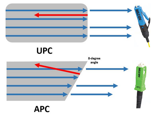
The main difference between UPC and APC connector is the fiber end face. UPC connectors are polished with no angle, but APC connectors feature a fiber end face that is polished at an 8-degree angle. With UPC connectors, any reflected light is reflected straight back towards the light source. However, the angled end face of the APC connector causes reflected light to reflect at an angle into the cladding versus straight back toward the source. This causes some differences in return loss. Therefore, UPC connector is usually required to have at least -50dB return loss or higher, while APC connector return loss should be -60dB or higher. In general, the higher the return loss the better the performance of the mating of two connectors. Besides the fiber end face, another more obvious difference is the color. Generally, UPC connectors are blue while APC connectors are green. The following figure picture shows the differences mentioned above intuitively.

UPC and APC Connector

Application Considerations of UPC and APC Connectors

There is no doubt that the optical performance of APC connectors is better than UPC connectors. In the current market, the APC connectors are widely used in applications such as FTTx, passive optical network (PON) and wavelength-division multiplexing (WDM) that are more sensitive to return loss. But besides optical performance, the cost and simplicity also should be taken into consideration. So it’s hard to say that one connector beats the other. In fact, whether you choose UPC or APC will depend on your particular need. With those applications that call for high precision optical fiber signaling, APC should be the first consideration, but less sensitive digital systems will perform equally well using UPC.

Fiberstore offers a variety of high speed fiber optic patch cables with LC, SC, ST, FC etc. connectors (UPC and APC polish). For more information about UPC and APC fiber optic connectors, please visit fs.com.

Related Article: 6 Steps Help to Choose Right Fiber Optic Patch Cable

Related Article: LC Fiber Connector, Adapter and Cable Assemblies

One Small Problem When We Choose the Fiber Patch Cable

Share

There is a common phenomenon that people are always able to distinguish different types of interfaces easily after corresponding to the given pictures, but when we choose the fiber patch cable, such as the polishing type also confused them, it shows UPC or APC, also confused us, recently I finally understand it and share my ideas with you.

First we can look from the definition, the above are acronyms for the following:

    • UPC – Ultra Physical Contact
    • APC – Angled Physical Contact

Only from the words we can have a simple understanding of them, in order to have a deeper understanding, there i named a few examples for you. Usually when we hear about the description like “fiber patch lc apc lc upc”, “e2000 fc apc”, “sc apc to sc upc single mode 9 125 simplex fiber optic patch cord cable”, what do this words apc upc mean? Then we will give you explanations. In Fiberstore, We use different color to distinguish them, the blue is UPC connector and the green is APC connector, shown as the figure.

In fact, it stands for the polish style of fiber optic core and connect the copper connector of copper cable as medium, and we need to know that the connections between the fiber optic connector and the ceramic core. Different fiber optic connector ring’s size, length and polished style is different, different polish of the fiber optic connector rings result in different performance, mainly on the back reflection. Generally, UPC is 50dB or higher and APC is 60dB or higher. All insertion loss of that they should be less than 0.3dB and the lower insertion loss is, the better performance they have, it is the reason why UPC connector is more widespread than APC. At the same time, there is a point we need to pay attention to, we all know that fiber optic cables can be divided into single mode and multimode fiber cables, but single mode fiber optic cables can be with UPC or APC polished connectors, while multimode fibers are not made with APC connectors. When we talk about the insertion loss, fiber optic attenuators have to be mentioned, it also has the diffent db to choose, as for the more knowledge about it, please always pay close attention to.

Fiberstore, you know, it offers kinds of fiber cables to choose, the different connector series all available for UPC/APC version, and we can also provide SM, MM, OM3 cables, simplex and duplex option, 0.9mm, 2.0 mm, 3.0mm cable diameter for choose, as for the fiber length, it can be customized according to your requirements.

Related Article:  Which Patch Cable Should I Choose for My Optical Transceiver?

The More and More Mature Fiber Optic Cables Transmission Technology

Share

Fiber optic media are any network transmission media that generally use glass, or plastic fiber in some special cases, to transmit network data in the form of light pulses. Within the last decade, optical fiber has become an increasingly popular type of network transmission media as the need for higher bandwidth and longer spans continues.

Fiber optic technology is different in its operation than standard copper media because the transmissions are “digital” light pulses instead of electrical voltage transitions. Very simply, fiber optic transmissions encode the ones and zeroes of a digital network transmission by turning on and off the light pulses of a laser light source, of a given wavelength, at very high frequencies. The light source is usually either a laser or some kind of Light-Emitting Diode (LED). The light from the light source is flashed on and off in the pattern of the data being encoded. The light travels inside the fiber until the light signal gets to its intended destination and is read by an optical detector.

Fiber optic cables are optimized for one or more wavelengths of light. The wavelength of a particular light source is the length, measured in nanometers (billionths of a meter, abbreviated “nm”), between wave peaks in a typical light wave from that light source. You can think of a wavelength as the color of the light, and it is equal to the speed of light divided by the frequency. In the case of Single-Mode Fiber (SMF), many different wavelengths of light can be transmitted over the same optical fiber at any one time. This is useful for increasing the transmission capacity of the fiber optic cable since each wavelength of light is a distinct signal. Therefore, many signals can be carried over the same strand of optical fiber. This requires multiple lasers and detectors and is referred to as Wavelength-Division Multiplexing (WDM).

Typically, optical fibers use wavelengths between 850 and 1550 nm, depending on the light source. Specifically, Multi-Mode Fiber (MMF) is used at 850 or 1300 nm and the SMF is typicallyused at 1310, 1490, and 1550 nm (and, in WDM systems, in wavelengths around these primary wavelengths). The latest technology is extending this to 1625 nm for SMF that is being used for next-generation Passive Optical Networks (PON) for FTTH (Fiber-To-The-Home) applications. Silica-based glass is most transparent at these wavelengths, and therefore the transmission is more efficient (there is less attenuation of the signal) in this range. For a reference, visible light (the light that you can see) has wavelengths in the range between 400 and 700 nm. Most fiber optic light sources operate within the near infrared range (between 750 and 2500 nm). You can’t see infrared light, but it is a very effective fiber optic light source.

Above: Multimode fiber is usually 50/125 and 62.5/125 in construction. This means that the core to cladding diameter ratio is 50 microns to 125 microns and 62.5 microns to 125 microns.  There are several types of multimode fiber patch cable available today,  the most common are multimode sc patch cable fiber, LC, ST, FC, ect.

Tips: Most traditional fiber optic light sources can only operate within the visible wavelength spectrum and over a range of wavelengths, not at one specific wavelength. Lasers (light amplification by stimulated emission of radiation) and LEDs produce light in a more limited, even single-wavelength, spectrum.

WARNING: Laser light sources used with fiber optic cables (such as the OM3 cables) are extremely hazardous to your vision. Looking directly at the end of a live optical fiber can cause severe damage to your retinas. You could be made permanently blind. Never look at the end of a fiber optic cable without first knowing that no light source is active.

The attenuation of optical fibers (both SMF and MMF) is lower at longer wavelengths. As a result, longer distance communications tends to occur at 1310 and 1550 nm wavelengths over SMF. Typical optical fibers have a larger attenuation at 1385 nm. This water peak is a result of very small amounts (in the part-per-million range) of water incorporated during the manufacturing process. Specifically it is a terminal –OH(hydroxyl) molecule that happens to have its characteristic vibration at the 1385 nm wavelength; thereby contributing to a high attenuation at this wavelength. Historically, communications systems operated on either side of this peak.

When the light pulses reach the destination, a sensor picks up the presence or absence of the light signal and transforms the pulses of light back into electrical signals. The more the light signal scatters or confronts boundaries, the greater the likelihood of signal loss (attenuation). Additionally, every fiber optic connector between signal source and destination presents the possibility for signal loss. Thus, the connectors must be installed correctly at each connection. There are several types of fiber optic connectors available today. The most common are: ST, SC, FC, MT-RJ and LC style connectors. All of these types of connectors can be used with either multimode or single mode fiber.

Most LAN/WAN fiber transmission systems use one fiber for transmitting and one for reception. However, the latest technology allows a fiber optic transmitter to transmit in two directions over the same fiber strand (e.g, a passive cwdm mux using WDM technology). The different wavelengths of light do not interfere with each other since the detectors are tuned to only read specific wavelengths. Therefore, the more wavelengths you send over a single strand of optical fiber, the more detectors you need.

Related Article:  Which Patch Cable Should I Choose for My Optical Transceiver?

Connectorized Couplings

Share

Quite often it is desirable to have a means of connecting two fibers together through a temporary mating device or connector. Figure 7.4 shows a common way to implement such a connector. Each fiber is placed in a ferrule whose function is to provide the mechanical support for the fiber and hold it in place tightly. The ferrule can be made out of plastic, metal, or ceramic materials. The central piece of the connector itself is an alignment sleeve. The two ferrules are inserted in the sleeve, and proper alignment between the cores is ensured because of the tight mechanical tolerances of the ferrules and the sleeve. The gap between the two fibers can be controlled by a mechanical stop which determines the exact stopping positions of the fibers. In some variations, the alignment sleeve is tapered to improve connector mating and demating.

Well-designed connectors provide low coupling loss, in the order of 0.1 dB or less. However, as shown in Fig. 7.5, a number of underirable situations can reduce the coupling efficiency. Figure 7.5a shows a case of two fibers with different core diameters. In general, whenver the numberical apertures of two fibers are different, the potential for power loss exists. In this case, light coupling from a narrower fiber core to a wide fiber core is easier and more efficient compared to coupling in the other direction. Figure 7.5b shows an example of poor concentricity. Fibers that do not provide a tigh concentricity tolerance may show large coupling variations depending on the orientation or from one pair of fibers to the next.

fiber connector

A large air gap, shown in Fig 7.5c, is another reason for loss of power. An air gap can result from incomplete insertion of the fiber or from mechanical problems inside the sleeve. It is also common for microscopic dust particles to get into fiber optic connector, preventing them from making proper conatact, or even scratching and damaging the fiber facets.

More dramatic power reduction results when dust particles land on the fiber core, blocking the light path. As a result, constant monitoring and cleaning of fiber facets are important to prevent such probems. Angular or lateral displacement, the mechanical tolerances are not tigh enough or when the dimensions of the sleeve and the ferrule do not match.

A fiber connector is characterized by several important parameters. As noted before, the most important factor is insertion loss, or simply connector loss. Another important factor is repeatability. If the same two fibers are connected through the same connector a number of times, each time the coupling will be slightly different. A good connector assmbly provides a small standard deviation for coupling efficiency across multiple insertions. Another desiralbe specification of a fiber connector is low return loss, i.e., a low back reflection. Return loss is defined as the ratio of the reflected power from the connector to the input power. For example, a return loss f 30 dB means 0.001 of the input power is reflected back from the connector. A conector must also be resistant and show a minimal coupling variation in the presence of normal mechanical forces such as axial and lateral forces. This is a practical requirement because in a normal environment it is likely for the connector to encounter a range of mechanical forces.

A wide range of connectors have been designed and are in use in the industry. Here we give an overview of some of the most popular types.

Straight tip or ST connectors are one of the more common type of connectors and in wide use in many applications. The ferrule diameter in an ST connector is 2.5 mm. ST connectors are spring loaded and enaged by a twist-and-lock mechanism.

Fixed connector or FC connectors use an alignment key and a threaded (screw-on) socket and are similar to the popular SMA connectors used in electronics. They are in wide use in single-mode applications and provide low insertion loss and high repeatability.

Subscriber connector, or SC, is another common type of connector. The advantage of SC connectors is that they are engaged by a push-and-snap mechanism, without the need for any roation. This make plugging and unplugging them very easy and also reduces wear out. Moreover, a higher connector density is achieved. Many transceivers provide either an SC receptacle connector, or a pigtail SC connector, as their optical interface. The push-and-snap feature of SC connectors thus provides very convenient and easy way of connecting to optical trasceivers. SC connectors are avaiable in simplex and duplex variations. The ferrule diameter in an SC connector is 2.5 mm.

SC fiber optic patch cable is one of the earliest stype and one of the most commonly used fiber optic cable, it is convenient to use and cost saving, SC fiber optic patch cord is widely uesed in fiber optic networks. SC fiber patch cable is with zirconia sleeve and plastic housing. The common type of SC connector patch cord, there are SC to SC fiber patch cord,  SC to LC Fiber Optic Patch Cable, SC to ST Fiber Optic Patch Cable,  SC to FC Fiber Optic Patch Cable, ect.

The LC or small form factor connector is similar to the SC, but with half the size. The diameter of the ferrule in an LC connector is 1.25 mm, vs 2.5 mm for most other connectors. This allow for twice the connector density for a given space. Because of their compactness, LC connectors have become more popular and are used in many high-end transceivers such as SFPs and XFPs.  LC fiber optic patch cable is with a small form factor (SFF) connector and is ideal for high density applications. LC fiber optic patch cord connector has a zirconia ceramic ferrule measuring 1.25mm O.D. with a PC or APC endface, and provides optimum insertion and return loss.

Related Article:  Which Patch Cable Should I Choose for My Optical Transceiver?

How To Use Magnifier Inspect Fiber Optic Connector

Share

We can use magnifier to check the fiber optic connector pin end, which quickly determined that the connector insertion loss is high or low, the need for re-grinding. With this method, you only need a few seconds, you can initially conclude that the connector meets the quality requirements. Than the use of instruments that measure the specific optical connector insertion loss value, and then determine wheter the quality meets the requirements, greatly reducing the time and improve efficiency.

Testing Equipment

Using fiber magnifier to check fiber optic connector pins end, we need at least the following equipment:

1. 200 times or 400 times of fiber optic magnifier(according to the type of fiber connector to check the selection of suitable fiber adapters);

2. Pure alcohole and lens paper (hairless soft paper);

3. Light source (we used here instead of incandescent bulbs);

Testing Steps

Check the following steps:

1. Remove the dust cap at the end of the connector to check;
2. Insert the connector in the magnifying glass of the adapter;
3. If you can not see the field of vision magnifier pin end, then adjust the position of magnifier adjustment knob until the pin end graphics all entered the field of vision;
4. Adjust the focal length of the magnifying glass to the right position, making the pin end graphics to clear;
5. Check the pin end, works well for grinding connector. Its face should be round, very smooth, the end of the fiber core is flush with the pin, and showed concentric ring shape; If there is dust (or defects), use lens paper (hairless soft paper) stick of pure alcohol wipe until the surface no dust (or you can see the clear flaws);
6. The other end of the connector to remove the dust cap, and make the end of the pins on the incandescent bulbs, we just checked in the connector end can see the light, otherwise the connector where a fiber optic cable has broken;
7. Repeat the above steps, check again, you will see a very bright core pin end view may find minor flaws;
8. Exchange ends of the connector, repeat the above steps to check the other end;
9. Mark the connector end of the existing problems with the tag, using appropriate methods, or grinding or re-assembled connector, and then repeat the steps above to be checked.

Analysis of test results

The use of a magnifier fiber optic connector for the inspection, we can see that a very good grinding effect fiber connector pin end face should have graphical features, it can have a variety of different types of defects that the end face of the connector graphical features. According to what we see different kinds of graphics, combined with our analysis, we can take the appropriate measures for improvement, in order to ensure the quality of the connector.

Recommended to use at least 200 times (preferably 400 times) of the optical magnifier to be checked. In order to check the accuracy, certainly with and without the use of incandescent bulbs in both cases with a magnifier to check connector end. In both cases the control of the end face of the pattern that can better determine whether defective.

For a good grinding effect connectors, we do not need any additional processing, instrumentatioin can be used directly for subsequent testing. If the connector is more obvious defects (based on experience needed to judge), its loss is likely higher, beyond the acceptable range of technical requipments, we can directly determine the quality problems. But for smaller connectors defective, the loss may be within the required range, then we need to use instrumentation to determine the actual test.

How to determine whether the effect of the connector polishing is “Good”?

If the connector pin end and core are round, smooth, while the fiber core is flush with the pin end, concentricity good, it is “good”, and without blemish.

If one connector looks “bad”, then the center or not circular, or is not smooth, or concentricity deviation is large, or the presence of other defects. For example, if the fiber has partially broken, then its will not be a full circle core.

The most serious situation is that we are under a magnifier to see the clear outline of the core of the phenomenon we call “fragmentation”. More than a brief introduction to how to determine a connector is a “good” or “bad”.

LC Connector And LC Attenuator

Share

fiber optic connector terminates the end of an optical fiber and enables quicker connection and disconnection than splicing. The fibers are mechanically coupled and aligned to ensure that light can pass.

There has been many different connectors introduced through the development of fiber optic components previously many years. A lot of companies and individuals happen to be trying to improve the options that come with certain connectors to be able to gain control of the fiber optic industry, but only few have been successful. As technology increases, various fiber optic components have become less expensive.

There are various color codes for connectors and they have changed throughout the years. In early stages of fiber optic history, orange, black or grey represented multimode connectors and yellow represented single mode. These original codes became complicated with the introduction of metallic connectors so colored boots were developed, like FC and ST. Now, beige boots stand for multimode, blue means single mode and APC or angled connectors are represented by green boots.

The LC connector is a universal connector. It is available in simplex and duplex configurations and is half how big the SC and utilizes a 1.25mm ferule. The LC is highly favored for single mode and is easily terminated with an adhesive. They’re actively replacing the SC connectors in corporate environments due to their smaller size.

Built on style with LC, LC attenuators really are a combination of a connector on a definite end, as well as an adapter on the other. This enables so that it is “plugged-in” to just about any LC adapter. The assembly contains a ferrule that’s accessible in standard Polish connectors (PC) and 8 degree angle Polish (APC). They’re backward suitable for existing transmission equipment, while the APC attenuators provide superior reflection required for high power and analog equipment. LC fiber optic attenuators are designed to provide horizontal spectral attenuation over the full spectrum vary from 1280nm to 1624nm. This way the LC attenuators expand the capability of optical networks by enabling using the E-band (1400-nm window) for optical transmission.

LC fiber optic attenuator is a passive device accustomed to reduce light signal intensity without significantly changing the waveform itself. It provides a type of metal-ion doped fiber which reduces the noiseless signal because it passes through. This process of attenuation allows for higher performance than fiber splices or fiber offsets or fiber clearance, which function by misdirecting rather than absorbing the joyful signal. This is often a requirement in Dense Wave Division Multiplexing (DWDM) and Erbium Doped Fiber Amplifier (EDFA) applications in which the receiver can’t accept the signal produced by a high-power light source.

LC fiber optic attenuators are key in controlling manipulating the electricity of an optical path in fiber optic telecommunication systems. LC Build-on fiber optic attenuators are used to reduce excess optical power from the transmitter that can result in over-saturation of the receiver.

These optical attenuators feature simple and rugged structure utilizing ion doped fiber because the attenuating material. They can be placed directly on the active equipment and therefore are able to withstand over 1W of extraordinary power light exposure for longer periods of time, which makes them well-suited to EDFA and other high-power applications.