Category Archives: Single Mode Fiber (SMF)

40G Deployment: The Cost Difference Between SMF and MMF

Share

40G network are now being extensively adopted within LANs and data centers. 100G is still predominantly in the carrier network, but could soon extend its stretch to your local network. There exists much confusion as to whether to choose single-mode fiber (SMF) or multimode fiber (MMF) for deploying 40G bandwidth, considering the single mode vs multimode fiber cost. As well as how to get fully prepared for scaling to higher-speed 100G. If you are hesitating to make the choice, you may find this article helpful.
40G Cost: Difference Between SMF and MMF

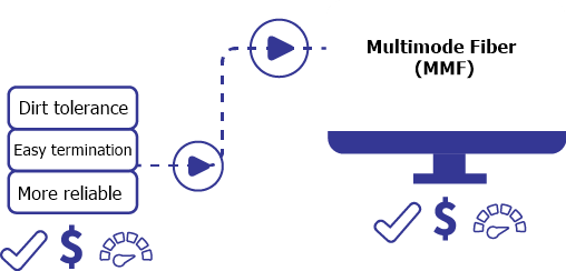
Multimode Fiber (MMF): Cost-effective With Higher Tolerance to Dirt

Cost-effectiveness: Multimode fiber (MMF) has been evolving to handle the escalating speed: OM3 has been superseded by OM4 and OM5 is there ready to use. MMF has a wider array of short distance transceivers that are easier to get. One of the liable argument that in favor of using MMF is that multimode optics use less power than single-mode ones, but only in condition that you have tens of thousands of racks. In essence, MMF still has its position under certain circumstances, like cabling within the same rack, in Fiber Channel and for backbone cabling in some new construction buildings.

smf mmf

Tolerance to Dirt: Multimode fiber tends to have a lot more tolerance to dirty connections than single-mode fiber. It can handle very dirty couples or connectors to ensure reliable and consistent link performance. Besides, it is easy to terminate, and more accommodating bend radius. So MMF is preferred by links that change frequently or are less than permanent.
smf mmf

Single-mode Fiber (SMF): Higher Capability and Better Future-proofing

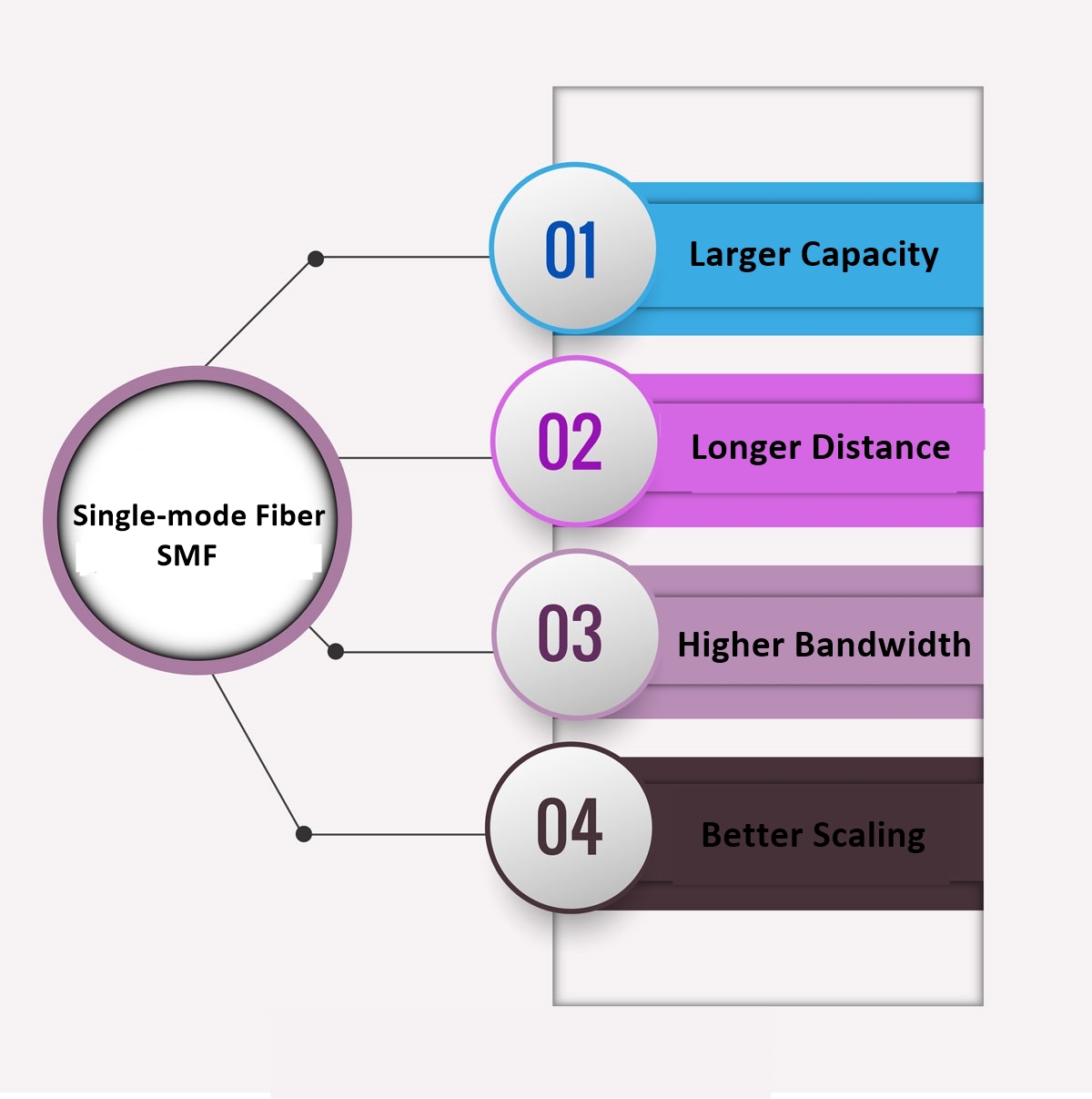
Speed capability: Capacities are really vital for network growth. SMF does so with relatively larger capability than that of MMF. The gap between SMF and MMF cabling is much wider for high-density, high-speed networks. If you want to go further with SMF, say scaling to 100G or beyond, you simply need to upgrade the optics. Unlike using MMF, in which you have to upgrade the glass (OM3 to OM4 to OM5), the labor cost concerning this cannot be underestimated. The capacity for scaling of SMF alone makes it worth the cost. You can use single-mode for almost everything, no need for media conversion. SMF offers enough bandwidth to last a long time, making it possible to upgrade 100 Gbps to Tbps with CWDM/DWDM.
smf mmf

Future proofing: Despite the fact that SM optical transceivers usually cost higher than MM optics, SMF cabling is cheaper and can support much longer distance and reliable performance. Not to mention that bandwidth on SMF keeps going up and up on the same old glass. The good news is that the cost of SMF is dropping in recent years, and it is redesigning to run with less power, thus advocators of SMF think that it is pretty much the only rational choice for infrastructure cabling and the sure winner for today and tomorrow.

SMF and MMF: A Simple Comparison of Cost

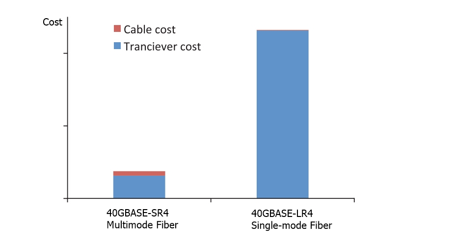
There is no doubt that SMF is a better investment in the long run, but MMF still has a long way to go in data center interconnections. In fact the price difference of SMF optics and MMF optics can be minimized if you choose the right solution. Assuming to connect two 40G devices at 70 m away, let’s see the single mode vs multimode fiber cost for deployment in the following chart.

Module Connector Type SMF or MMF Price 2 Connections 4 Connections 6 Connections
40GBASE-SR4 MPO12 MMF, OM4 $49.00 $564.48 $1128.96 $1693.44
40GBASE-BiDi LC MMF, OM4 $300.00 $1534.24 $2734.24 $3934.24
40GBASE-LR4 LC SMF, OS2 $340.00 $1,609.84 $2,969.84 $4,329.84
80 Gbit 160 Gbit 240 Gbit


Conclusion

Choosing the right fiber for your network application is a critical decision. Understanding your system requirements in order to select the appropriate fiber will maximize the value and performance of your cabling system. Be sure to select the right cable on the basis of aspects including link length, performance, and of course costs. FS provides a broad range of 40G optical transceivers and fiber patch cables with superior quality and fair price. For more details, please visit www.fs.com.

Related Article: Single Mode vs Multimode Fiber: What’s the Difference? 


What Kind of Single Mode Fiber Should You Choose?

Share

As we all know, multimode fiber is usually divided into OM1, OM2, OM3 and OM4. Then how about single mode fiber? In fact, the types of single mode fiber seem much more complex than multimode fiber. There are two primary sources of specification of single mode optical fiber. One is the ITU-T G.65x series, and the other is IEC 60793-2-50 (published as BS EN 60793-2-50). Rather than refer to both ITU-T and IEC terminology, I’ll only stick to the simpler ITU-T G.65x in this article. There are 19 different single mode optical fiber specifications defined by the ITU-T.

Name Type
ITU-T G.652 ITU-T G.652.A, ITU-T G.652.B, ITU-T G.652.C, ITU-T G.652.D
ITU-T G.653 ITU-T G.653.A, ITU-T G.653.B
ITU-T G.654 ITU-T G.654.A, ITU-T G.654.B, ITU-T G.654.C
ITU-T G.655 ITU-T G.655.A, ITU-T G.655.B, ITU-T G.655.C, ITU-T G.655.D, ITU-T G.655.E
ITU-T G.656 ITU-T G.656
ITU-T G.657 ITU-T G.657.A, ITU-T G.657.B, ITU-T G.657.C, ITU-T G.657.D

Each type has its own area of application and the evolution of these optical fiber specifications reflects the evolution of transmission system technology from the earliest installation of single mode optical fiber through to the present day. Choosing the right one for your project can be vital in terms of performance, cost, reliability and safety. In this post, I may explain a bit more about the differences between the specifications of the G.65x series of single mode optical fiber families. Hope to help you make the right decision.

G.652
The ITU-T G.652 fiber is also known as standard SMF (single mode fiber) and is the most commonly deployed fiber. It comes in four variants (A, B, C, D). A and B have a water peak. C and D eliminate the water peak for full spectrum operation. The G.652.A and G.652.B fibers are designed to have a zero-dispersion wavelength near 1310 nm, therefore they are optimized for operation in the 1310-nm band. They can also operate in the 1550-nm band, but it is not optimized for this region due to the high dispersion. These optical fibers are usually used within LAN, MAN and access network systems. The more recent variants (G.652.C and G.652.D) feature a reduced water peak that allows them to be used in the wavelength region between 1310 nm and 1550 nm supporting Coarse Wavelength Division Multiplexed (CWDM) transmission.

G.652 

G.653
G.653 single mode fiber was developed to address this conflict between best bandwidth at one wavelength and lowest loss at another. It uses a more complex structure in the core region and a very small core area, and the wavelength of zero chromatic dispersion was shifted up to 1550 nm to coincide with the lowest losses in the fiber. Therefore, G.653 fiber is also called dispersion-shifted fiber (DSF). G.653 has a reduced core size, which is optimized for long-haul single mode transmission systems using erbium-doped fiber amplifiers (EDFA). However, its high power concentration in the fiber core may generate nonlinear effects. One of the most troublesome, four-wave mixing (FWM), occurs in a Dense Wavelength Division Multiplexed (CWDM) system with zero chromatic dispersion, causing unacceptable crosstalk and interference between channels.

G.653

G.654
The G.654 specifications entitled “characteristics of a cut-off shifted single mode optical fiber and cable.” It uses a larger core size made from pure silica to achieve the same long-haul performance with low attenuation in the 1550-nm band. It usually also has high chromatic dispersion at 1550 nm, but is not designed to operate at 1310 nm at all. G.654 fiber can handle higher power levels between 1500 nm and 1600 nm, which is mainly designed for extended long-haul undersea applications.

G.655
G.655 is known as non-zero dispersion-shifted fiber (NZDSF). It has a small, controlled amount of chromatic dispersion in the C-band (1530-1560 nm), where amplifiers work best, and has a larger core area than G.653 fiber. NZDSF fiber overcomes problems associated with four-wave mixing and other nonlinear effects by moving the zero-dispersion wavelength outside the 1550-nm operating window. There are two types of NZDSF, known as (-D)NZDSF and (+D)NZDSF. They have respectively a negative and positive slope versus wavelength. The following picture depicts the dispersion properties of the four main single mode fiber types. The typical chromatic dispersion of a G.652 compliant fiber is 17ps/nm/km. G.655 fibers were mainly used to support long-haul systems that use DWDM transmission.

G.655

G.656
As well as fibers that work well across a range of wavelengths, some are designed to work best at specific wavelengths. This is the G.656, which is also called Medium Dispersion Fiber (MDF). It is designed for local access and long haul fiber that performs well at 1460 nm and 1625 nm. This kind of fiber was developed to support long-haul systems that use CWDM and DWDM transmission over the specified wavelength range. And at the same time, it allows the easier deployment of CWDM in metropolitan areas, and increase the capacity of fiber in DWDM systems.

G.657
G.657 single mode fiberG.657 optical fibers are intended to be compatible with the G.652 optical fibers but have differing bend sensitivity performance. It is designed to allow fibers to bend, without affecting performance. This is achieved through an optical trench that reflects stray light back into the core, rather than it being lost in the cladding, enabling greater bending of the fiber. As we all know, in cable TV and FTTH industries, it is hard to control bend radius in the field. G.657 is the latest standard for FTTH applications, and, along with G.652 is the most commonly used in last drop fiber networks.

From the passage above, we know that different kind of single mode fiber has different application. Since G.657 is compatible with the G.652, some planners and installers are usually likely to come across them. In fact, G657 has a larger bend radius than G.652, which is especially suitable for FTTH applications. And due to problems of G.643 being used in WDM system, it is now rarely deployed, being superseded by G.655. G.654 is mainly used in subsea application. According to this passage, I hope you have a clear understanding of these single mode fibers, which may help you make the right decision.

Related Article: https://community.fs.com/blog/what-kind-of-single-mode-fiber-should-you-choose.html

SMF or MMF? Which Is the Right Choice for Data Center Cabling?

Share

Selecting the right cabling plant for data center connectivity is critically important. The wrong decision could leave a data center incapable of supporting future growth, requiring an extremely costly cable plant upgrade to move to higher speeds. In the past, due to high cost of single-mode fiber (SMF), multimode fiber (MMF) has been widely and successfully deployed in data center for many years. However, as technologies have evolved, the difference in price between SMF and MMF transceivers has been largely negated. With cost no longer the dominant decision criterion, operators can make architectural decisions based on performance. Under these circumstances, should we choose SMF or MMF? This article may give you some advice.

MMF Can’t Reach the High Bandwidth-Distance Needs
MMF datacenterBased on fiber construction multimode fiber has different classifications types that are used to determine what optical signal rates are supported over what distances. Many data center operators who deployed MMF OM1/OM2 fiber a few years ago are now realizing that the older MMF does not support higher transmit rates like 40GbE and 100GbE. As a result, some MMF users have been forced to add later-generation OM3 and OM4 fiber to support standards-based 40GbE and 100GbE interfaces. However, multimode fiber’s physical limitations mean that as data traffic grows and interconnectivity speeds increase, the distance between connections must decrease. The only alternative in an multimode fiber world is to deploy more fibers in parallel to support more traffic. Therefore, while MMF cabling has been widely and successfully deployed for generations, its limitations now become even more serious. Operators must weigh unexpected cabling costs against a network incapable of supporting new services.

SMF Maybe a Viable Alternative
Previously, organizations were reluctant to implement SMF inside the data center due to the cost of the pluggable optics required, especially compared to MMF. However, newer silicon technologies and manufacturing innovations are driving down the cost of SMF pluggable optics. Transceivers with Fabry-Perot edge emitting lasers (single-mode) are now comparable in price and power dissipation to VCSEL (multimode) transceivers. Besides, Where MMF cable plants introduce a capacity-reach tradeoff, SMF eliminates network bandwidth constraints. This allows operators to take advantage of higher-bit-rate interfaces and wave division multiplexing (WDM) technology to increase by three orders of magnitude the amount of traffic that the fiber plant can support over longer distances. All these factors make SMF a more viable option for high-speed deployments in data centers.

SMF datacenter

Comparison Between SMF and MMF
10GbE has become the predominant interconnectivity interface in large data centers, with 40GbE and 100GbE playing roles in some high-bandwidth applications. Put simply, the necessity for fiber cabling that supports higher bit rates over extended distances is here today. With that in mind, the most significant difference between SMF and MMF is that SMF provides a higher spectral efficiency, which means it supports more traffic over a single fiber using more channels at higher speeds. This is in stark contrast to multimode fiber, where cabling support for higher bit rates is limited by its large core size. This effectively limits the distance higher speed signals can travel over MMF fiber. In fact, in most cases, currently deployed MMF cabling is unable to support higher speeds over the same distance as lower-speed signals.

Name Interface FP (SMF) VCSEL (MMF)
Link Budget (dB)
4 to 6 2
Reach (in meters) (Higher value is better)
10GbE 1300 300
40GbE 1300 150
100GbE 1300 <100

Conclusion
As operators consider their cabling options, the tradeoff between capacity and reach is important. Network operators must assess the extent to which they believe their data centers are going to grow. For environments where users, applications, and corresponding workload are all increasing, single mode fiber offers the best future proofing for performance and scalability than multimode fiber. And because of fundamental changes in how transceivers are manufactured, those benefits can be attained at prices comparable to SMF’s lower performing alternative.

Source: Single Mode vs Multimode Fiber: What’s the Difference?

Frequently Asked Question About Fiber Patch Cord

Share

What Is Fiber Patch Cord?

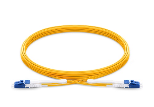
A fiber patch cord can be a cable that connects devices allowing information to pass together. Patch cords certainly are a common method of setting up wired connections between devices, including connecting a tv with a digital cable box using coaxial cable. These cords are used for any kind of signal transference, such as in a television, radio or computer network. These cables are manufactured with standard fiber optic cabling and are terminated with fiber optic connectors for both ends.

fiber patch cord

What Is Fiber Patch Cord Used for?

There are several application areas for optical fiber cable, including connecting computer workstations to outlets and connecting fiber optic patch panels or optical cross-connect distribution centers.

What Are the Most Common Fiber Optic Patch Cables?

There are lots of common forms of fiber patch cables and your network may need a number of these phones operate most efficiently. Professionals use a number of ways to categorize the most frequent fiber patch cables, like the fiber cable type, the termination connector types, the optical fiber modes, the dimensions of the fiber cable, as well as the various styles of polishing the connectors. FS.COM offer several types of common patch cable, it provides 10G OM3/OM4 fiber patch cable; 9/125 single-mode and OM2 50/125, OM1 62.5/125 multimode fiber patch cable having a number of connector types including LC, SC, ST, FC, MU, and MTRJ.

What Are Fiber Optic Cable Types?

There are the main kinds of fiber cable: Simplex, Duplex. A Simplex fiber patch cable has one fiber and one connector on each side. A Duplex fiber optic cable features two fibers and a couple connectors on both ends. Either each fiber will probably be marked separately (e.g., A and B) or the connector boots uses different colors to think the polarity of each connector.

How Are Fiber Optic Patch Cables Terminated?

You can find basically two methods to terminate a fiber cable: utilizing the same connector type on both ends from the cable (e.g., LC fiber patch cable: LC to LC) and taking advantage of two different connectors on each side from the cable (e.g. ST-SC fiber patch cable) which is also known as the Hybrid termination.

What Are the Most Common Connector Types for Fiber Patch Cord?

Typically the most popular connector types are SC, ST, LC, MTRJ, MU, and FC.

What Modes Are Utilized in Fiber Patch Cord?

Currently, there are three different modes which can be used in fiber patch cords: single mode, multimode, and 10G multimode. Single mode fiber cables count on 9/125 micron fiber cable with single mode connectors on both ends with the cable. Multimode fiber optic patch cables use 62.5/125 micron or 50/125 micron fiber cabling and therefore are terminated with multimode fiber optic connectors on each end of the cable. 10Gb multimode fiber optic patch cords use enhanced 50/125 micron fiber that is optimized for 850nm VCSEL based 10Gb Ethernet. They are usually suitable for existing network equipment and will offer 300% more bandwidth than traditional 62.5/125 multimode fibers. These cables will also be rated for distances up to 300 meters.

Why Are There Different Connector Polishing Styles?

Fiber optic connectors were created, manufactured and polished to different shapes to reduce back reflection. Back reflection grades generally vary from -30dB to -60dB. Remember that polishing is especially important for applications in which single mode fiber has been used.

What Are Other Names for Fiber Patch Cord?

This really is by no means a thorough list of synonyms of these cables, but we now have heard them called: fiber optic patch cords, fiber patch cables, fiber optic jumpers, fiber jumper cables, duplex fiber jumpers, fiber wire, LAN fiber, network fiber, optic cables, network glass, plus more.

What Information Should I Provide If I Want to Modify the Fiber Patch Cord?

The following:

1. Quantity, and Length in meters.

2. The number of fibers. Simplex or Duplex.

3. Connector type for both ends, they could ‘t be exactly the same on both ends.

4. Singlemode or Multimode fiber. If Multimode please advise if 62.5/125 or 50/125, or 50/125 laser optimized.

5. PVC or Plenum jacket.

6. It is possible to send your customized detail info to the email: sales@fs.com, our sales will contact you as soon as possible, many thanks.

Difference Between OS1 and OS2 Single Mode Fiber Cable

Share

As we all know, multimode fiber is usually divided into OM1, OM2, OM3 and OM4. Then how about single mode fiber cable? In general, single mode fiber cable is categorized into OS1 and OS2 fiber. OS1 and OS2 are cabled single mode optical fiber specifications. In fact, there are many differences between OS1 vs OS2 single mode fiber. This text will make a comparison between OS1 vs OS2 and then give you a guide on how to choose the right fiber optic cable for your applications.

OS1 single mode fibers are compliant with ITU-T G.652A or ITU-T G.652B standards. Besides, the low-water-peak fibers defined by ITU-T G.652C and G.652D also come under OS1 single mode fibers. That is to say, OS1 is compliant with specifications of ITU-T G.652. However, OS2 single mode fibers are only compliant with ITU-T G.652C or ITU-T G.652D standards, which  means OS2 is explicitly applied to the low-water-peak fibers. These low-water-peak fibers are usually used for CWDM (Coarse Wavelength Division Multiplexing) applications.

OS1 vs OS2Besides the standards, the main difference between OS1 and OS2 single mode fiber is the cable construction. Typically, OS1 cabling is tight-buffered construction, which is usually used for indoor applications, such as campus or data center. Yet OS2 cabling is loose-tube design. Cable with this construction is appropriate for outdoor cases like street, underground and burial. For this reason, OS1 indoor fiber has greater loss per kilometer than OS2 outdoor fiber. In general, the maximum attenuation for OS1 is 1.0 db/km and for OS2 is 0.4db/km. As a result, the maximum transmission distance of OS1 single mode fiber is 2 km but the maximum transmission distance of OS2 single mode fiber can reach 5 km and is up to 10 km. Then for all these reasons, OS1 is much cheaper than OS2. There is point need to pay attention to is that both OS1 and OS2 single mode fibers over their distance will allow speeds of 1 to 10 gigabit Ethernet. All of these differences between OS1 and OS2 discussed above are listed in the table below. You can get a clear understanding from it.

Name OS1 OS2
Standards ITU-T G.652A/B/C/D ITU-T G.652C/D
Construction Tight buffered Loose tube
Application Indoor Outdoor
Attenuation 1.0db/km 0.4db/km
Distance 2 km 10 km
Price Low High

Learning about the differences between OS1 vs OS2 single mode fiber cable, then which cable should you choose? First, if you want to use for the indoor application, OS1 is better for you. However, if used for outdoor application, you should choose OS2. Second, there is no benefit to be gained in using OS2 cable if under 2 km. OS2 is best for distance over 2 km. Finally, you should note that OS1 is much cheaper than OS2. In order to save cost, if the OS1 is enough for your application there is no need to use OS2. Fiberstore offers OS1 and OS2 single mode fiber cable as well as all kinds of multimode fiber cable. It is your optimal selection.

Related Articles:

What are OM1, OM2, OM3 and OM4 multimode fiber?
Single Mode Fiber: How Much Do You Know?
What Kind of Single-mode Fiber Should You Choose?

What’s the Difference: Single Mode vs Multimode Fiber

Share

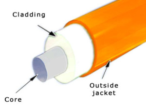
fiber cable diagAn optical fiber is a flexible, transparent fiber made of extruded glass or plastic, slightly thicker than a human hair. Optical fibers are used most often as a means to transmit light between the two ends of the fiber and find wide usage in fiber-optic communications, where they permit transmission over longer distances and at higher bandwidths than wire cables. Optical fibers typically include a transparent core surrounded by a transparent cladding material with a lower index of refraction. Light is kept in the core by the phenomenon of total internal reflection which causes the fiber to act as a waveguide. In general, there are two kinds of optical fiber: fibers that support many propagation paths or transverse modes are called multimode fibers (MMF), while those that support a single mode are called single mode fibers (SMF). Single mode vs multimode fiber: what’s difference between them? Reading this text will help you get the answer.

Single Mode vs Multimode Fiber: What’s single mode optical fiber?

In fiber-optic communication, a single mode optical fiber (SMF) is an optical fiber designed to carry light only directly down the fibre – the transverse mode. For single mode optical fiber, no matter it operates at 100 Mbit/s or 1 Gbit/s date rates , the transmission distance can reach to at least 5 km. Typically, it is used for long-distance signal transmission.

single mode fiber

Single Mode vs Multimode Fiber: What’s multimode optical fiber?

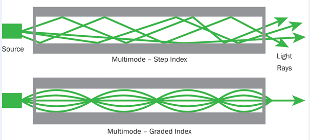
Multimode optical fiber (MMF) is a type of optical fiber mostly used for communication over short distances, such as within a building or on a campus. Typical transmission speed and distance limits are 100 Mbit/s for distances up to 2 km (100BASE-FX), 1 Gbit/s up to 1000m, and 10 Gbit/s up to 550 m. There are two kinds of multimode indexes: step index and graded index.

multimode fiber

What’s difference between single mode optical fiber and multimode?

  • Core diameter

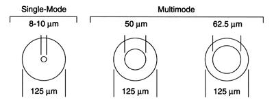
The main difference between multimode and single mode fiber is that the former has much larger core diameter, typically has a core diameter of 50 or 62.5 µm and a cladding diameter of 125 µm. While a typical single mode fiber has a core diameter between 8 and 10 µm and a cladding diameter of 125 µm.

Single Mode vs Multimode Fiber

  • Optical source
    Both lasers and LEDs are used as light sources. Laser light sources are significantly more expensive than LED light sources however they produce a light that can be precisely controlled and which has a high power. Because the LED light sources produce a more dispersed light source (many modes of light) these light sources are used with multimode
    cable. While a laser source is used (which produces close to a single mode of light) with single mode cable.

Single Mode vs Multimode Fiber

  • Bandwidth
    Since multimode fiber has a larger core-size than single mode fiber, it supports more than one propagation mode. Besides, like multimode fibers, single-mode fibers do exhibit modal dispersion resulting from multiple spatial modes, but the modal dispersion of single mode fiber is less than multi-mode fiber. For these reasons, single mode fibers can have a higher bandwidth than multi-mode fibers.
  • Jacket color
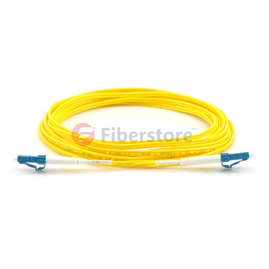
    Jacket color is sometimes used to distinguish multimode cables from single mode ones. The standard TIA-598C recommends, for non-military applications, the use of a yellow jacket for single mode fiber, and orange or aqua for multimode fiber, depending on type. Some vendors use violet to distinguish higher performance OM4 communications fiber from other types.

Single Mode vs Multimode Fiber

  • Modal dispersion
    The LED light sources sometimes used with multimode fiber produce a range of wavelengths and these each propagate at different speeds. This will lead to much modal dispersion, which is a limit to the useful length for multimode fiber optic cable. In contrast, the lasers used to drive single mode fibers produce coherent light of a single wavelength. Hence its modal dispersion is much less than multimode fiber. Due to the modal dispersion, multimode fiber has higher pulse spreading rates than single mode fiber, limiting multimode fiber’s information transmission capacity.

Single Mode vs Multimode Fiber

  • Price
    For multimode fiber can support multiple light mode, the price of it is higher than single-mode fiber. But in terms of the equipment, because single mode fiber normally uses solid-state laser diodes, therefore, the equipment for single mode fiber is more expensive than equipment for multimode fiber. And for this reason , the cost of using multimode fiber is much less than using single-mode fiber instead.

Single Mode vs Multimode Fiber: What kind of optical fiber should I choose?

This is based on transmission distance to be covered as well as the overall budget allowed. If the distance is less than a couple of miles, multimode fiber will work well and transmission system costs (transmitter and receiver) will be in the $500 to $800 range. If the distance to be covered is more than 3-5 miles, single mode fiber is the choice. Transmission systems designed for use with this fiber will typically cost more than $1000 due to the increased cost of the laser diode. Single mode vs multimode fiber: Do you know the differences now?

Related Article: Single Mode Fiber: How Much Do You Know?

Comparison Between OS1 and OS2 SMF Cables

The More and More Mature Fiber Optic Cables Transmission Technology

Share

Fiber optic media are any network transmission media that generally use glass, or plastic fiber in some special cases, to transmit network data in the form of light pulses. Within the last decade, optical fiber has become an increasingly popular type of network transmission media as the need for higher bandwidth and longer spans continues.

Fiber optic technology is different in its operation than standard copper media because the transmissions are “digital” light pulses instead of electrical voltage transitions. Very simply, fiber optic transmissions encode the ones and zeroes of a digital network transmission by turning on and off the light pulses of a laser light source, of a given wavelength, at very high frequencies. The light source is usually either a laser or some kind of Light-Emitting Diode (LED). The light from the light source is flashed on and off in the pattern of the data being encoded. The light travels inside the fiber until the light signal gets to its intended destination and is read by an optical detector.

Fiber optic cables are optimized for one or more wavelengths of light. The wavelength of a particular light source is the length, measured in nanometers (billionths of a meter, abbreviated “nm”), between wave peaks in a typical light wave from that light source. You can think of a wavelength as the color of the light, and it is equal to the speed of light divided by the frequency. In the case of Single-Mode Fiber (SMF), many different wavelengths of light can be transmitted over the same optical fiber at any one time. This is useful for increasing the transmission capacity of the fiber optic cable since each wavelength of light is a distinct signal. Therefore, many signals can be carried over the same strand of optical fiber. This requires multiple lasers and detectors and is referred to as Wavelength-Division Multiplexing (WDM).

Typically, optical fibers use wavelengths between 850 and 1550 nm, depending on the light source. Specifically, Multi-Mode Fiber (MMF) is used at 850 or 1300 nm and the SMF is typicallyused at 1310, 1490, and 1550 nm (and, in WDM systems, in wavelengths around these primary wavelengths). The latest technology is extending this to 1625 nm for SMF that is being used for next-generation Passive Optical Networks (PON) for FTTH (Fiber-To-The-Home) applications. Silica-based glass is most transparent at these wavelengths, and therefore the transmission is more efficient (there is less attenuation of the signal) in this range. For a reference, visible light (the light that you can see) has wavelengths in the range between 400 and 700 nm. Most fiber optic light sources operate within the near infrared range (between 750 and 2500 nm). You can’t see infrared light, but it is a very effective fiber optic light source.

Above: Multimode fiber is usually 50/125 and 62.5/125 in construction. This means that the core to cladding diameter ratio is 50 microns to 125 microns and 62.5 microns to 125 microns.  There are several types of multimode fiber patch cable available today,  the most common are multimode sc patch cable fiber, LC, ST, FC, ect.

Tips: Most traditional fiber optic light sources can only operate within the visible wavelength spectrum and over a range of wavelengths, not at one specific wavelength. Lasers (light amplification by stimulated emission of radiation) and LEDs produce light in a more limited, even single-wavelength, spectrum.

WARNING: Laser light sources used with fiber optic cables (such as the OM3 cables) are extremely hazardous to your vision. Looking directly at the end of a live optical fiber can cause severe damage to your retinas. You could be made permanently blind. Never look at the end of a fiber optic cable without first knowing that no light source is active.

The attenuation of optical fibers (both SMF and MMF) is lower at longer wavelengths. As a result, longer distance communications tends to occur at 1310 and 1550 nm wavelengths over SMF. Typical optical fibers have a larger attenuation at 1385 nm. This water peak is a result of very small amounts (in the part-per-million range) of water incorporated during the manufacturing process. Specifically it is a terminal –OH(hydroxyl) molecule that happens to have its characteristic vibration at the 1385 nm wavelength; thereby contributing to a high attenuation at this wavelength. Historically, communications systems operated on either side of this peak.

When the light pulses reach the destination, a sensor picks up the presence or absence of the light signal and transforms the pulses of light back into electrical signals. The more the light signal scatters or confronts boundaries, the greater the likelihood of signal loss (attenuation). Additionally, every fiber optic connector between signal source and destination presents the possibility for signal loss. Thus, the connectors must be installed correctly at each connection. There are several types of fiber optic connectors available today. The most common are: ST, SC, FC, MT-RJ and LC style connectors. All of these types of connectors can be used with either multimode or single mode fiber.

Most LAN/WAN fiber transmission systems use one fiber for transmitting and one for reception. However, the latest technology allows a fiber optic transmitter to transmit in two directions over the same fiber strand (e.g, a passive cwdm mux using WDM technology). The different wavelengths of light do not interfere with each other since the detectors are tuned to only read specific wavelengths. Therefore, the more wavelengths you send over a single strand of optical fiber, the more detectors you need.

Related Article:  Which Patch Cable Should I Choose for My Optical Transceiver?

The LC Connector in Fiber Management and Transceivers

Share

The LC connector system, standardized as TIA/EIA FOCIS-10, was designed specifically to address the needs of increasing network interconnect density.

In the past, fiber management systems (for D4, ST, FC and Biconic),have required twice as many individual connectors as copper systems, hence, crowding racks and closets (Fig. 2) with additional patch bays, management hardware and line terminating electronics. SFF connectors have either a unitary body design (FJ and MT-RJ) or a provision for clipping simplex connectors together to form a single SFF end (LC).

The LC connector provides the potential for twice the interconnect density in closets and racks when compared to a SC connector. Although, there is a point at which additional density cannot be utilized because of the difficulty in fiber routing inordinately large cable counts. Also at issue in these higher density racks, is the problem of disturbing adjacent circuits in MACs. Most important in fiber management, is the decreased footprint of the LC on electronics (hubs, switches, etc.) for fiber transceivers.

SFF Connector, SFP Transceivers and the march towards 10Gb/s Enterprise Networking

Original SFF transceivers (GBICs) on equipment have now been overshadowed by the SFP (“pluggable”versions of the SFF) transceiver. Equipment vendors are starting to offer SFP on switches/NICs for Gb/s Ethernet. The optical receptacle on the SFP for Fibre Channel and Gb/s Ethernet is the LC connector. Most major transceiver vendors, including early proponents of “MT-RJ-only” transceivers, now sell SFPs with the LC interface only.

On 200 pin XenPAK transceivers, only SFF options are specified in the Multi Source Agreement (MSA). Vendors have offered XenPAK with both SC and LC pigtails, but the majority offers “LC only” XenPAK product lines. The LC is also used in competing transceivers such as XenPAK, X2 and XFP.

LC Market Acceptance

The LC is the market leader in SFF connectors. Press releases from the major vendors of LCs (Lucent) and MT-RJs (Tyco/AMP) in similar time frames (mid 01) indicate unit volumes of 20 million and 3 million respectively.

According to the Fiber Optic Connector/Mechanical Splice Global Market Report by Electronicast, the North American Market for private network use of SFF connectors is expanding quite rapidly. In this report, the multimode LC is estimated to grow at double the rate of that of the multimode MT-RJ (Table 1). The difference embedded in the Electronicast data is the creation of new installations (LC) versus the support of existing facilities (MT-RJ).

The multimode MT-RJ found early support in 100BASE-F applications. In spite of this, the LC is becoming the optoelectronics interconnect solution for 1-10Gb/s applications. The emerging 10Gb/s market has forced transceiver vendors to evolve toward pluggable designs with the LC as the primary choice of interconnect.

The LC connector patch cable have LC to LC, LC to MT-RJ, LC to SC, LC ST fiber patch cable .  The LC fiber optic patch cable is with a small form factor (SFF) connector and is ideal for high density applications. The LC fiber patch connector has a zirconia ceramic ferrule measuring 1.25mm O.D. with either a PC or APC end face, and provides optimum insertion and return loss. The LC fiber patch cable connector is used on small diameter mini-cordage (1.6mm/2.0mm) as well as 3.0mm cable. LC fiber cable connectors are available in cable assembled or one piece connectors. The LC fiber optic assemblies family is Telcordia, ANSI/EIA/TIA and IEC compliant.

lc fiber optic patch cable

We offer LC fiber cables and LC fiber patch, including single mode 9/125 and multimode 50/125, multimode 62.5/125, LC-LC, LC-SC, LC-ST, LC-MU, LC-MTRJ, LC-MPO, LC-MTP, LC-FC, OM1, OM2, OM3. Other types also available for custom design. Excellent quality and fast delivery.

Talk about LC connector, the common connector type we have seen, there are FC connector, SC connector, ST connector, ect. The following is some connector type features.

FC: A metal screw on connector, with a 2.5mm ferrule, developed by NTT. The ruggedness of this connector leads to its extensive use at the interfaces of test equipment. It is also the most common connector used for PM, polarization maintaining, connections. Please note that there are currently four different specifications for the key width on FC connectors and for the slot width on FC adapters. Therefore not all FC connectors will fit into all FC adapters.

LC: As mall form factor plastic push/pull connector, with a 1.25mm ferrule, developed by Lucent. The LC has been referred to as a miniature SC Connector. It is mainly used in the United States.

MTP: A push/pull ribbon connector, which holds up to 12 fibers. The 12-fiber capacity allows for very dense packing of fibers and a reduction in the number of connectors required.

SC: A plastic push-pull connector, with a 2.5mm ferrule, developed by NTT. Push-pull connectors require less space in patch panels than screw on connectors. The SC is the second most commonly used connector for PM, polarization maintaining, connections.

ST: A metal bayonet coupled connector, with a 2.5mm ferrule, developed by AT&T. The ferrule moves as load is applied to the cable in this aging design. There is a version of the ST, which the Navy uses extensively, where the ferrule does not move as a load is applied to the cable.

Fiberstore has a global reputation for bringing best-in-class technology and design concepts to the marketplace. Added to close customer relationships, decades of experience in the industry and outstanding service and support, make Fiberstore the right choice for fiber optic components and systems that will splice your fiber optic components together. We offer fiber optic patch cable, fiber optic cable, fiber optic transceivers, ect. In particular, Fiberstore products include optical subsystems used in fiber-to-the-premise, or FTTP, deployments which many telecommunication service providers are using to deliver video, voice, and data services.

Related Article:  Which Patch Cable Should I Choose for My Optical Transceiver?

Overview of 16 Gbps Fiber Channels

Share

Offering considerable improvements from previous FC speeds, 16 Gbps FC uses 64b/66b encoding, retimers in modules, and transmitter training. Doubling the throughput of 8 Gbps to 1,600 Mbps, it uses 64b/66b encoding to increase the efficiency of the link. 16 Gbps FC links also use retimers in the optical modules to improve link performance characteristics, and electronic dispersion compensation and transmitter training to improve backplane links. The combination of these technologies enables the 16 Gbps FC to provide some of the highest throughput density in the industry, making data transfers smoother, quicker, and cost-efficient.

Although 16 Gbps FC doubles the throughput of 8 Gbps FC to 1600MBps, the line rate of the signals only increases to 14.025 Gbps because of a more efficient encoding scheme. Like 10 Gbps FC and 10 Gigabit Ethernet (GbE), 16 Gbps FC uses 64b/66b encoding, that is 97% efficient, compared to 8b/10b encoding, that is only 80% efficient. If 8b/10b encoding was used for 16 Gbps FC, the line rate would have been 17 Gbps and the quality of links would be a significant challenge because of higher distortion and attenuation at higher speeds. By using 64b/66b encoding, 16 Gbps FC improves the performance of the link with minimal increase in cost.

To remain backward compatible with previous Fiber Channel speeds, the Fiber Channel application specific integrated circuit (ASIC) must support both 8b/10b encoders and 64b/66b encoders.

As seen in Figure 2-1, a Fiber Channel ASIC that is connected to an SFP+ module has a coupler that connects to each encoder. The speed-dependent switch directs the data stream toward the appropriate encoder depending on the selected speed. During speed negotiation, the two ends of the link determine the highest supported speed that both ports support.

The second technique that 16 Gbps FC uses to improve link performance is the use of retimers or Clock and Data Recovery (CDR) circuitry in the SFP+ modules. The most significant challenge of standardizing a high-speed serial link is developing a link budget that manages the jitter of a link. Jitter is the variation in the bit width of a signal due to various factors, and retimers elliminate most of the jitter in a link. By placing a retimer in the optical modules, link characteristics are improved so that the links can be extended for optical fiber distances of 100 meters on OM3 fiber. The cost and size of retimers has decreased significantly so that they can now be intergrated into the modules for minimal cost.

The 16 Gbps FC multimode links were designed to meet the distance requirements of the majority of data centers. Table 2-2 shows the supported link distances over multimode and single-mode fiber 16 Gbps FC was optimized for OM3 fiber and supports 100 meters. With the standardization of OM4 fiber, Fiber Channel has standardized the supported link distances over OM4 fiber, and 16 Gbps FC can support 125 meters. If a 16 Gbps FC link needs to go farther than these distances, a single-mode link can be used that supports distances up to 10 kilometers. This wide range of supported link distances enables 16 Gbps FC to work in a wide range of environments.

Another important feature of 16 Gbps FC is that it uses transmitter training for backplane links. Transmitter training is an interactive process between the electrical transmitter and receiver that tunes lanes for optimal performance. The 16 Gbps FC references the IEEE standards for 10GBASE-KR, which is known as Backplane Ethernet, for the fundamental technology to increase lane performance. The main difference between the two standards is that 16 Gbps FC backplanes run 40% faster than 10GBASE-KR backplanes for increased performance.

Fiberstore introduces it’s new OM4 Laser-Optimized Multimode Fiber (LOMMF) “Aqua” cables, for use with 40/100Gb Ethernet applications. These new technology, 50/125um, LC/LC Fiber Optic cables, provide nearly three times the bandwidth over conventional 62.5um multimode fiber, with performance rivaling that of Singlemode cable, at a much reduced cost. LOMMF cable allows 40/100Gb serial transmission over extended distances in the 850nm wavelength window, where low-cost Vertical Cavity Surface Emitting Lasers (VCSELs) enable a cost-effective, high-bandwidth solution. OM4 fiber optic patch cord is ideally suited for LAN’s, SAN’s, and high-speed parallel interconnects for head-ends, central offices, and data centers. Tripp Lite warrants this product to be free from defects in material and workmanship for Life. Now the following is the OM4 fiber from Fiberstore.

OM4 SC to SC fiber patch cord feature an extremely high bandwidth–4700MHz*km, more than any other mode. They support 10GB to 550 meters and 100GB to 125 meters. These cables are suitable for high-throughput applications, such as data storage. These cables are fully (backwards) compatible with 50/125 equipment as well as with 10 gigabit Ethernet applications. These connectors utilize a UPC (Ultra Physical Contact) polish which provides a better surface finish with less back reflection. With the OM4 cables, you can use longer lengths than OM3 cables while still having an excellent connection.

We offer a huge selection of single and multimode patch cords for multiple applications: mechanical use, short in-office runs, or longer runs between and within buildings, or even underground. Gel-free options are available for less mess, and Bend Insensitive cables for minimizing bend loss, which can be difficult to locate and resolve.

Related Article:  Which Patch Cable Should I Choose for My Optical Transceiver?

Small Form Factor Fiber-Optic Connectors

Share

One of the more popular styles of fiber-optic connectors is the small form factor (SFF) style of connector. SFF connectors allow more fiber optic terminations in the same amount of space over their standard-sized counterparts. The two most popular are the mechanical transfer registered jack (MT-RJ or MTRJ), designed by AMP, and the Local Connector (LC), designed by Lucent.

MT-RJ

The MT-RJ fiber optic connector was the first small form factor fiber optic connector to see widespread use. It is one-third the size of the SC and ST connectors it msot often replaces. It had the following benefits:

● Small size
● TX and RX strands in one connector
● Keyed for single polarity
● Pre-terminated ends that require no polishing or epoxy
● Easy to use

LC

Local Connector is a newer style of SFF fiber optic connector that is overtaking MT-RJ as fiber optic connector. It is especially popular for use which Fiber Channel adapters and Gigabit Ethernet adapters. It has similar advantages to MT-RJ and other SFF-type connectors but is easier to terminate. It uses a ceramic insert as standard-sized fiber-optic connectors do. Figure 1.21 shows an example of the LC connector. Mentioned fiber optic connector, we know fiber optic patch cords, a fiber optic patch cord is constructed from a core with a high refractive index, surrounded by a coating with a low refractive index that is surrounded by a protective jacket. Transparency of the core permits transmission of optic signals with little loss over great distances. The coating’s low refractive index reflects light back into the core, minimizing signal loss. The protective jacket minimizes physical damage to the core and coating.

Connector design standards include FC, SC, ST, LC, MTRJ, MPO, MU, SMA, FDDI, E2000, DIN4, and D4. Cables are classified by the connectors on either end of the cable; some of the most common cable configurations include FC-FC, FC-SC, FC-LC, FC-ST, SC-SC, and SC-ST.

lc to lc fiber patch cord is used to send high-speed data transmissions throughout your network. LC/LC fiber optic cables connect two components with fiber optic connectors. A light signal is transmitted so there is no outside electrical interference. Our LC/LC fiber optic patch cables are 100% optically tested for maximum performance. We have all lengths and connectors available.

Multimode LC/LC fiber optic patch cable send multiple light signals. They are 62.5/125µ. Common connectors are ST, LC, SC and MTRJ. Our 62.5/125µ LC/LC multi-mode fiber cables can support gigabit ethernet over distances up to 275 meters.

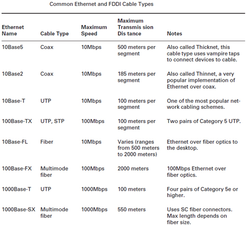
Cable Type Summary

common-ethernet

Fiber optic patch cables are used for linking the equipment and components ,we have fiber optic patch cable with different fiber connector types,our low insertion loss and low back reflection .Axen Technologies fiber patch cable is widely applied in Telecommunication Networks ,Gigabit Ethernet and Premise Installations.

Related Article:  Which Patch Cable Should I Choose for My Optical Transceiver?