Author Archives: Amelia.Liu

The Fiber Optic Patch Cord Reliability

Share

Fiber optic patch cords are one of the simplest elements in any optical network, consisting of a piece of fiber optic cable with a connector on each end. Despite its simplicity, the Fiber Optic Patch Cord can have a strong effect on the overall performance of the network. The majority of problems in any network occur at the physical layer and many are related to the patch cord quality, reliability, and performance. Therefore, using patch cords that are more reliable helps reduce the chance of costly network downtime. This article mainy the patch cord reliability.

Network designers would prefer components with a history of proven long-term performance. However, since optical networking is a relatively new technology, there is no significant long-term data for many components. Therefore, designers must rely upon testing from the component manufacturer or supplier that can simulate this history and assure the quality and reliability over the life of the network. This paper discusses the importance of quality, reliability, and performance as they relate to industry standards and manufacturing practices. The performance of the patch cord is also studied using a “perfect patch cord” and polishing observations as tools to understand patch cord principles.

Patch cord reliability is guaranteed not only by using quality components and manufacturing processes and equipment, but also by adherence to a successful Quality Assurance program. While patch cords themselves are typically tested 100% for insertion loss and return loss, if applicable, there are many other factors that need to be monitored to insure the quality of the patch cord.

One of the most important factors is the epoxy. Epoxies typically have a limited shelf life and working life, or “pot life.” This information is readily available from the manufacturer. It is absolutely necessary that both of these criteria be verified and maintained during manufacture. Epoxy beyond its expiration date needs to be discarded. Chemical changes affecting the cured properties of the epoxy can occur after this date. This date can also be dependent on storage conditions, which need to be observed.

Most epoxies used in fiber optic terminations are two-part epoxies and, while they cure at elevated temperatures, preliminary cross-linking will begin upon mixing. Once this has started, the viscosity of the epoxy can begin to change, making application more difficult over time. The epoxy can become too thick to fill the ferrule properly and too viscous to enable a fiber to penetrate, causing fiber breakage.

Many of the tooling used in patch cord assembly also has periodic maintenance and a limited tool life. This includes all stripping, cleaving and crimping tools. Most stripping tools, whether they are hand tools or automated machines, can be damaged by the components of the cable, most notably the aramid yarn strength members. Buffer strippers will dull with prolonged usage, increasing the likelihood that they will not cleanly cut the buffer. This can lead to overstressing the fiber when the buffer is pulled off. When a cleaving tool wears out and a clean score is not made, it is almost impossible to detect during manufacturing. However, the result could be non-uniform fiber breakage during the cleave, which can result in either breaking or cracking the fiber below the ferrule endface. In this instance, the connector will have to be scrapped. Even crimp tools require periodic maintenance to insure the proper forces and dimensions are consistent. Crimp dies also have a tendency to accrue epoxy build-up, which can affect the crimping dimensions and potentially damage the connector.

The integrity of the incoming materials and manufacturing processes, once specified, needs to be adhered to all the appropriate guidelines and procedures. The importance of these materials not only has a strong influence on product reliability, but also on product performance.

Fiber optic patch cords are fiber optic cables used to attach one device to another for signal routing. It compresses in the entire electric network plank and room that wall plank and the flexibility cabinet needs, causes such the person who passes room merely considerably traditional FC,LC,ST and SC’s connection box in parts.Intelligently the bright and beautiful corporation adopts well-developed technique and installation, and carrying on scale manufacture, the produce performance is good, and the quality is steady dependable. Fiberstore manufactures fiber optic patch cables, fiber optic patch cords, and pigtails. There are LC, SC, ST, FC, E2000, SC/APC, E2000/APC, MU, VF45, MT-RJ, MPO/MTP, FC/APC, ST/APC, LC/APC, E2000, DIN, D4, SMA, Escon, FDDI, RoHS compliant, LSZH, Riser,Plenum, OFNR, OFNP, simplex, duplex, single mode, 9/125, SM, multimode, MM, 50/125, 62.5/125; armored fiber optic patch cords, OM4 patch cord, waterproof fiber optic patch cords, ribbon fiber optic cables and bunched fiber optic cables.

Related Article:  Which Patch Cable Should I Choose for My Optical Transceiver?

Core And Cladding In Fiber Optic Cable

Share

Fiber optic cables transmit data through very small cores at the speed of light. Significantly different from copper cables, fiber optic cables offer high bandwidths and low losses with the help of the core and cladding. And it allows high data-transmission rates over long distances. Light propagates throughout the fiber cables according to the principle of total internal reflection.

There are three common types of fiber optic cables: single-mode, multimode, and graded-index. Each has its advantages and disadvantages. There also are several different designs of fiber optic cables, each made for different applications. In addition, new fiber optic cables with different core and cladding designs have been emerging; these are faster and can carry more modes. While fiber optic cable are used mostly in communication systems, they also have established medical, military, scanning, imaging, and sensing applications. They are also used in optical fiber devices and fiber optic lighting.

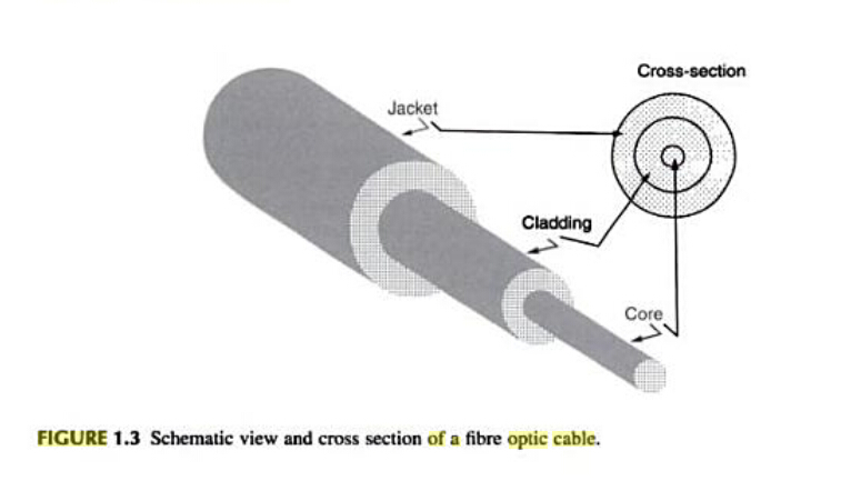
Fiber optic cable is a filament of transparent material used to transmit light, as shown in Figure 1.2. Virtually all fiber optic cables share the same fundamental structure. The centre of the cable is referred to as the core. It has a highter refractive index than the cladding, which surrounds the core. The contact surface between the core and the cladding creates an interface surface that guides the light; the difference between the refractive index of the core and cladding is what causes the mirror like interface surface, which guides light along the core. Light bounces through the core from one end to the other according to the principle of total internal reflection, as explained by the laws of light. The cladding is then covered with a protective plastic or PVC jacket. The diameters of the core,cladding, and jacket can vary widely; for a single fiber optic cable can have core, cladding, and jacket diameters of 9, 125, and 250 um, respectively.

Figure 1.3 shows the structure of a typical fiber optic cable. The cores of most fiber optic cables are made from pure glass, while the cladding are made from less pure glass. Glass fiber optic cable has the lowest attenuation over long distances but comes at the highest cost. A pure glass fiber optic cable has a glass cladding. Fiber optic cable core and cladding may be made from plastic, which is not as clear as glass but is more flexible and easier to handle. Compared with other fiber cables, Plastic Optical Fiber Cable is limited in power loss and bandwidth. However, they are more affordable, easy to use, and attractive in applications where high bandwidth or low loss is not a concern. A few glass fiber cable cores are clad with plastic. Their performance, though not as good as all-glass fiber cables, is quite respectable.

core and cladding in fiber optic cable

The jacket is made from polymmer (PVC, plastic, etc.) to protect the core and the cladding from mechanical damage. The jackets has several major attributes, including bending ability, abrasion resistance, static fatigue protection, toughness, moisture resistance, and the ability to be stripped. Fiber optic cable jackets are made in different colours for colour-coding identification. Some optical fibers are coated with a copper-based alloy that allows operation at up to 700 and 500℃ for short and long periods, respectively.

Fiberstore is a leading supplier of Fiber Optic Cable and components into the umbilical and towed array products for the oil & gas sector. The key technology for these products is Fiberstore’s patented stainless steel fiber optic tube technology which packages the optical fiber in the best possible way resulting in a robust, compact product that is suitable for the high pressure of the subsea environment. Fiberstore will customize the design to meet your needs to include different fiber counts, fiber types, metal types, tube sizes, belting materials, armor type, armor size, armor count, encapsulation types, color, print, packaging and length.

Related Article:  Which Patch Cable Should I Choose for My Optical Transceiver?
Related Article:  The Advantages and Disadvantages of Optical Fiber

More Characteristics of Fiber Optic Cable

Share

When light from a source is sent through a fiber-optic cable, the ligth wave both bounces around inside the cable and passes through the cable to the outlet protective jacket. When a light signal inside the cable bounces off the cable wall and back into the cable, this is called reflection. When a light signal passes from the core of the cable into the surrounding material, this is called refraction. Figure 3-9 demonstrates the differece between reflection and refraction.

Light can be transmitted through a fiber-optic cable using two basic techniques. The first technique, called single-mode transmission, requires the use of a very thin fiber-optic cable and a very focused light source, such as a laser. When a laser is fired down a narrow fiber, the light follows a tight beam, and so there is less tendency for the light wave to reflect or refract. Thus, this technique allows for a very fast signal with little signal degradation (and thus less noise) over long distances. Because lasers are used as the light source, single-mode transmission is a more expensive techique than the second fiber-optic cable signaling techique. Any application that involves a large amount of data transmitted at high speeds is a candidate for single-mode transmission.

The second signaling technique, called multimode transmission, uses a slightly thicker fiber cable and an unfocused light source, such as an LED. Because the light source is unfocused, the light wave experiences more refraction and reflection (i.e, noise) as it propagates through the wire. This noise results in signals that cannot travel as far or as fast as the signals generated with the single-mode technique. Correspondingly, multimode transmission is less expensive than single-mode transmission. Local area networks that employ fiber-optic cables often use multimode transmissions.

Single-mode and multimode transmission techniuqes use fiber-optic cable with different characteristics. The core of single-mode fiber-optic cable is 8.3 microns wide, and the material surrounding the fiber – the cladding – is 125 microns wide. Hence, single-mode fiber optic cable is labeled 8.3/15 cable. The core of multimode fiber optic cable is most commonly 62.5 microns wide, and the cladding is 125 microns. Multimode fiber optic cable is labeled 62.5/125 cable. Othe sizes of multimode fiber optic cable include 50/125 and 100/140 microns.

Bulk fiber optic cable comes in lots of types, depending on where it will be installed. Where to buy fiber optic cable? As the best OEM fiber optic cable manufacturer, Fiberstore provides a wide range of quality optical fiber cables with detailed specifications displayed for your convenient selecting. Per foot price of each fiber cable is flexible depending on the quantities of your order, making your cost of large order unexpected lower. Customers can also have the flexibility to custom the cable plant to best fit their needs. Only fiber cable that meets or exceeds industry standards is used to ensure quality products with best-in-class performance. Fiberstore offers an extensive line of off the shelf bulk fiber optic cable to address your fiber installation needs. We stock 62.5/125, 50/125, and 9/125 bulk fiber optic cable in simplex, duplex (zip cord), breakout, and distribution styles.

Related Article:  Which Patch Cable Should I Choose for My Optical Transceiver?
Data Center Patch Cords Organized

Share

The benefit of having neat and organized cabling obviously applies to patch cords as much as structured cabling. When you go beyond green considerations, it can be argued that it’s more important to have neat patch cords than structured cabling. Data Center users typically interact with a patching field when installing or servicing hardware rather than structured cabling. Patching fields can be more challenging to maintain in some server environments, however, due to frequent hardware changes and sometimes minimal management of how patches are run.

You can follow several strategies to keep Data Center patch cords organized, thereby improving airflow to equipment, reducing energy consumption of your cooling infrastructure, and easing troubleshooting. (Not to mention maintaining the professional appearance of your Data Center.)

■ Employ a distributed cabling hierarchy: Already mentioned as beneficial for structured cabling, this approach can help with Fiber Optic Patch Cables as well. Having Data Center networking patch fields divided into smaller segments around the Data Center mitigates cabling density and potentially improves airflow to the associated networking equipment.
■ Right-size port counts: Planning the correct number of ports in your Data Center – and reserving space for future expansion of patch fields – helps avoid messy cabling. Installing too many ports can result in unnecessarily large cable bundles; installing too few can trigger picemeal cabling additions in the future that fit awkwardly with the original cabling infrastructure.
■ Use ample wire management: However many connections you install in your network patching fields, be sure to include sufficient vertical and horizontal wire management to handle the maximum quantity of patch cords you plan for. This is of particular importance for some Category 6A patch cords because of their increased outsied cable diameters and soild copper core wire construction. This type of cord promotes a cable memory that can be increasingly difficult to manage as the number of patch cords multiply.
■ Prepatch networking connections: Hardware density in modern Data Centers can involve thousands of cable connections in a single server row. Prepatching networking devices and patch fields all together, before servers are installed, helps ensure that cabling is routed neatly.
■ Provide patch cords in different length – and use them: Stock commonly used types of patch cords in your Data Center in multiple lengths so that whoeer install your hardware can make a neat connection between devices and patching fields. That means correctly routing cabling through the available wire management rather than making a straight-line connection that blocks access to hardware or patch panels. It also means choosing the right length of cable length, so there is no slack to be either coiled up and hidden in the wire management system or left hanging at the end of a connection.

Implementing these cabling practices, first when designing a new Data Center and then when operating, doesn’t just make the facility greener by improving airlow and conserving cabling material, it also makes it easier to use and less prone to accidental down-time.

Fiberstore manufactures and stocks fiber optic patch cables. Our stock cables feature FC/PC, FC/APC, and SMA connectors, and use single mode (SM), polarization-maintaining (PM), or multimode (MM) fiber. Buy LC fiber  optic cable series, same day shipping to your countyre now. We offer ar-coated cables for fiber-to-free space use, lightweight cables for optogenetics, high-power cables, and many other specialty fiber patch cables from stock. We also offer multimode fiber bundles, as well as custom patch cables with 24 hour turnaround on many orders. If you do not see a stock cable that is suitable for your application, please contact us.

Related Article:  Which Patch Cable Should I Choose for My Optical Transceiver?
How to Get the Correct Cables and Converter For HDTV

Share

The Apple TV doesn’t include a cable for connecting it to your TV, so you need to get a cable unless you already have a suitable one. Similary, you need a cable if you want to connect your Apple TV to speakers or a stereo. If your speakers or stereo are analog instead of digital, you need a digital-to-analog converter, as well. If you want to connect your Apple TV to a wired rather than a wireless network, you need an Ethernet cable. The rest of this section covers what you need to get your Apple TV connected.

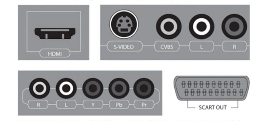
At this writing, the Apple TV comes with only an High-Definition Multimedia Interface (HDMI) port for output. This is great for new and newish TVs that have one or more HDMI ports. However, if you have an older TV that donesn’t have an HDMI port, you need to get a converter cable or adapter. Take a few minutes to look at your TV’s documentation to find out which connections it suppports. If you can’t find the documentation, look at the TV itself. Figure 1.2 shows the four main types of connection: HDMI, Component Video, Composite Video, and SCART.

HDMI

Using an HDMI cable for an HDTV

For an HDTV, you normally need only an HDMI cable. If you already have a suitable HDMI cable, you’re all set. If not, you can pick one up from most any store that carries electrical goods.

When you’re choosing an HDMI cable, consider the following:

HDMI logo: Make sure that the cable carries the HDMI logo, as shown in Figure 1.3. This means that the cable was tested and approved by the HDMI Organization ― the body responsible for setting and maintaing the HDMI standard. HDMI-approved cables cost a few dollars more than those that are unapproved, but you can be confident that they are of acceptable quality.

Length: If you can position your Apple TV near your TV, a three-or six-foot cable may be long enough. If the Apple TV needs to be farther away ― get a longer cable. Extremely long cables can cause signal problems (see the sidebar about HDMI cable length), so don’t buy one that is longer than you actually need.

Cost. Expect to pay between $10 and $20 for a quality HDMI cable of standard length (3 to 10 feet). Audiovisual specialists make and sell extremely expensive HDMI cables, and some cost thousands of dollars. Current expert opinion, though, is that basic HDMI cables are fine as long as they are properly make and you don’t mistreat them.

HDMI Standards. Some manufactures advertise their cables as being compliant with different standards, such as HDMI 1.2 and HDMI 1.3. HDMI 1.3 supports Deep Color, a feature that uses extra colors to give a richer display, automatic lip-synching, and high-resolution soundtracks, including Dolby TrueHD. At this writing, the Apple TV doesn’t use these features, so you don’t need HDMI 1.3 cables. If you can choose between an HDMI 1.2 or 1.3 cables. If you can choose between an HDMI 1.2 or 1.3 cable, go for the 1.3 for future compatibility.

Using a component or composite video converter

If you have a standard TV rather than an HDTV, you most likely need to use a Component Video input or Composite Video input instead of an HDMI input. If your TV provides both types of connections, use Component Video, because it gives higher quality. If your TV has only one type of connection, you’re stuck with that type.

HDMI Converter

How Long Can an HDMI Cable Be?

Unlike many other audio-visual specifications, the HDMI specification doesn’t get a strong enougth signal to produce a good picture.

If the HDMI cable is too long or damaged, you may notice the follwing symptoms:

● Distortion in the picture.
● Single pixels failing to appear in the correct color.
● No video at all, even though the audio plays correctly.

If you need to run the HDMI cable a long distance and find these symptoms appearing, get an HDMI signal restorer to strengthen the signal.

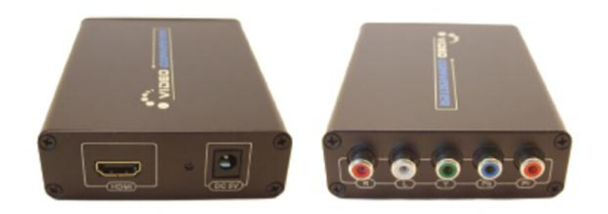
If your TV has a Component Video input, get an HDMI-to-Component Video converter like the one shown in Figure 1.4. This  HDMI video multiplexer is small box with an HDMI input at one end, as shown on the left in Figure 1.4, and a Component Video output at the other, as shown on the right in Figure 1.4. You also need a Component Video cable if you don’t already have one.

If your TV has a Composite Video input, you can get an HDMI-to-Composite Video converter. Similar to the Component Video converter, this is a small box with an HDMI input at one end, as shown on the left in Figure 1.5, and a Conposite Video output at the other, as shown on the right in Figure 1.5. You also need a Composite Video cable to connect the converter to your TV’s input.

Related Article:  Which Patch Cable Should I Choose for My Optical Transceiver?
                  

Twisted Pair Cable Plant Components

Share

Twisted pair cable (Cat5e/Cat6/Cat7 cable, etc.) is good for transferring balanced differential signals. The practice of transmitting signals differentially dates back to the early days of telegraph and radio. The advantages of improved signal-to-noise ratio, crosstalk, and ground bounce that balanced signal transmission bring are particularly valuable in wide bandwidth and high fidelity systems. By transmitting signals along with a 180 degree out-of-phase complement, emissions and ground currents are theoretically canceled. This eases the requirements on the ground and shield compared to single ended transmission and results in improved EMI performance.

Normally, a twisted pair cable plant requires more than just the cabling, it needs other important components as well. Listed below are the most common five components you should know about to work with the twisted pair cable.

Five Common Twisted Pair Cable Plant Components

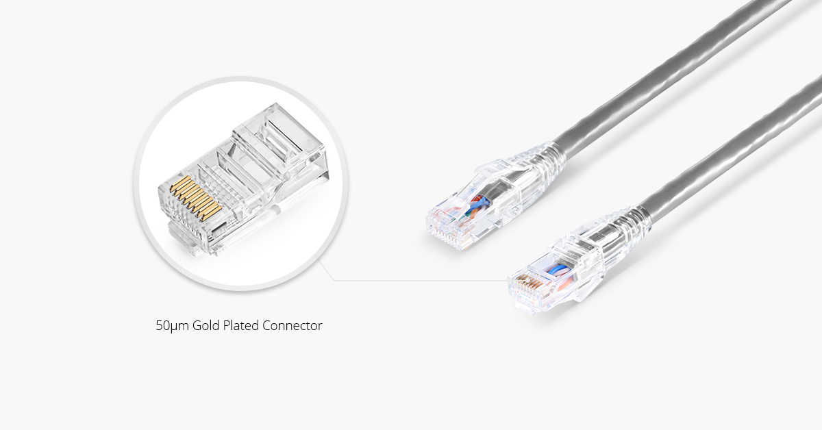
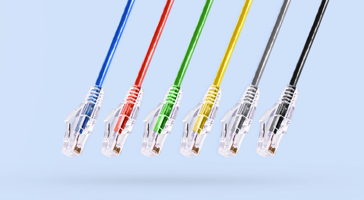
● RJ-45 Connectors: Whether STP or UTP, most twisted-pair cabling uses registered jack 45 (RJ-45) connectors to plug into network interfaces or other networked devices. This connector looks much like the RJ-11 connector on modular phone jacks, but it’s larger and contains eight wire traces rather than the four or six in an RJ-11. An RJ-45 connector, often called an RJ-45 plug, is most commonly used in patch cables (Cat6 cable, Cat6a cable, Cat7 cable, etc.), which are used to connect computers to hubs and switches and computers to RJ-45 wall jacks.

RJ45 Connector For Twisted Pair Cable

● Patch Cable: A patch cable (Cat5e cable, for example) is a short cable for connecting a computer to an RJ-45 jack or connecting a patch-panel port to a switch or hub. Patch cables can be made with inexpensive tools, two RJ-45 plugs, and a length of TP cable. Although making a patch cable is easy, most network administrators prefer buying ready-made cables to save time.

patch cables

RJ-45 Jacks: An RJ-45 jack is what you plug an RJ-45 connector into when the computer is in a work area away from hubs and switches. It has a receptacle for an RJ-45 plug on one side and a place to terminate, or “punch down,” the TP cabling on the other side. RJ-45 jacks are usually placed behind wall plates when cables are run inside walls but can also be recessed into the floor or placed in surface-mounted boxes if the cabling runs on the outside of walls.

Patch Panel: Patch panels are used to terminate long runs of cable from the work area (where the computer are) to the wiring closet (where the switches and hubs are). Patch panels are like RJ-45 jacks, in that they have a receptacle on one end and punchdown terminals on the other, but a patch panel can usually accommodate 12, 24, or 45 cables.

● Distribution Racks: Distribution racks (also called 19-inch racks because the upright rails are 19 inches apart) hold network equipment, such as routers and switches, plus patch panels and rack-mounted servers. They’re usually found in wiring closets and equipment rooms.

 Related Articles: 

Which Patch Cable Should I Choose for My Optical Transceiver?
What’s the Difference Between Twisted Pair vs Coaxial Cable vs Fiber Optic

How to Install Twisted-Pair Cable Connectors?

Video Patch Panel With Patch Cable

Share

The jacks commonly used in patch panels in the U.S. conform to Western Electric standard dimensions. The number of insertion cycles a jack can endure should be rated in the tens of thousands. The factors affecting the life and reliablility of a jack include contact wear and failure of the termination switch. Descirable features include the following:

● Contacts fully isolated from the panel.
● Sealed metal housing to keep out contaminants and provide EMI protection.
● Easy replacement from the front of the panel.
● Low VSWR (below 600 MHz)
● High signal isolation (40 dB)
● 75 Ω characteristic impedance.
● Wide designation strips, making it easier to label the field and to allow more flexibility in selecting names that will fit on the lables.

If a patch cable is inserted in the signal path of a timed video system, it will delay the signal by an amount determined by its length and physical properties. The patch thereby alters the timing of the signal path. This can be avoided by using phase-matched normal-through fiber patch panels. The design of these patch panels anticipates the delay caused by a fixed length of patch cable by including that length in the loop-through circuit.

With phase-matched panels, the normaling connection in each connector module includes a length of cable that provides a fixed delay through the panel, usually 3 ft (0.914m). If a patch cord of the same length as the internal cable is used to make connections between patch points, the delay will be the same as that of the normal-through panel. When a fiber optic patch cord is plugged in, it is substituted for the loop cable through the swiching mechanism normally used in normalled patch connectors. Thus, critical timing relationships can be maintained.

In a normal uncompensated patch panel, when a cable is used to patch between two points on the panel, the length of the patch cord is added to that of the cables connected to the patch. The additional cable length delays the signal by approximately 1.52 ns/ft (5 ns/m). To avoid the delays associated with conventional patch panels, phase-matched normal-through video patch panels should be used.

If phase-matched patch panels are used, all of the patch cord must be the same length as the delay built into the patch panel. Obviously, if all of the patch cords must be the same short length for the phase-matched panel, it would not be possible to patch between panels that are separated by a longer distance than the cord can reach. This limitation should be considered when laying out patch panels in a fiber enclosure.

Color-coded cables can be specified. When different-length patch cords are specified, different colors can be used to distinguish one length from another for better cable management.

Fiberstore specializes in fiber optic patch cable assemblies and fiber optic network devices manufacturing since 1995, we are known as the fiber optic cable manufacturer for the excellent products quality, competitive prices, fast delivery and good service.  Our fiber optic cables are available with combinations of LC, SC, ST, FC, and MTRJ connectors and come in 1, 2, 3, 5, and 10 meter lengths (and OM3 cables up to 30 meters).  We offer LC fiber optic cable, SC fiber optic patch cables, SC LC fiber patch cable ect. We not only offer OEM fiber optic patch cord assemblies to some world leading companies in this industry, but  also cooperate with many other companies from all over the world and support these partners to win in the market.

HDMI Extender (Optical Use) About Chromecast

Share

The HDMI Extender is also optional, and helps you connect the Chromecast even if does not plug directly into your television. It is, by all accounts, an extension. That is to say, if you cannot reach the back of your television (if it is mounted to the wall, perhaps), the extension will give you the room you need to still use the device. It may also improve your Wi-Fi reception, so hang onto it in case your television prompts you to use it during set up. If you do need it, coonect the HDMI video multiplexer into the television first, and then plug the Chromecast into the extender. This will keep you from damaging the small device before you even get to use it!

There is a small instruction manual that comes in the box as well. Small describes this instructional sheet perfectly because it appears to have been designed and printed for a baby doll to read. It is so tiny, in fact, that it is hard to turn the pages without feeling silly. The good news is, the Chromecast is simplicity as its best, so the manual isn’t really necessary. But it is cute.

You should already have some sort of television or display monitor which has an available HDMI port to plug the Chromecast into. If it has a USB port, that’s also helpful for plugging in the micro-USB power cable to. If your TV doesn’t have the USB port, don’t worry, you can plug the micro-USB cable (included) into the included USB/AC power adapater, and then plug that into a nearby wall outlet.

You’ll want to have a wireless network set up in your home (with a wireless modern and possibly a wireless router). If you have a secure wireless network, make sure you have any password or other info handy to enter for the Chromecast setup.

For streaming content to your Chromecast on your TV or monitor, you’ll need a Mac, Windows or Chromebook Pixel computer.

Additionally, you can use an Android or iOS smartphone or tablet. At this time, only certain apps will work on the mobile devices for streaming content. These include YouTube and Netflix, which you’ll be able to use. In the future, there is very likely to be more apps developed that will allow you to use the Chromecast streaming to your TV.

Video Extender is a kind of hardware devices that allow users to convert video in one signal format into another. For example, the video Extender built by Fiberstore provide simple plug-and-play operation, and include SDI Extenders, HDMI Extenders, VGA Extenders and DVI Extenders. This series of devices enables users to link previous technology formats with the newest updates without requiring a complete overhaul of their audio/video system. S-Video, Composite, Components, Coaxial and RGB Video Extenders. Wide screen video formats are supported, as well. These devices can be used when users to convert a video signal from some devices such as camera, notebook computer to a television. Next we will explain these video Extenders over fibers in detail.

Brief Introduction to Fiber Optic Patch Cords

Share

Fiber optic patch cord is the simplest fiber optic elements, consisting of a short length of optical fiber with a connector on either end. Since they are used to connect various components and instruments in a fiber optic system, their characteristics in terms of loss and aging determine the overall performance of the system. In principle, when two patch cords are connected, if the fibers are identical, it should result in almost zero loss. In actual practice the loss may not be very small since the fiber may not be completely concentric with the connector center, there could be dust at the tip of the connector, or there could be misalignments when two patch cords are mated. Fiber optic patch cord with different types of fibers and different connector types are available. The typical insertion loss of patch cords is about 0.4 dB, with a return loss of better than 50 dB.

We mustn’t forget the role that optical patch cords play in the practical use of an optical cable system. A patch cord is a short length of a simple optical cable, typically one to five meters, that is used to connect the active or final equipment into the cable plant, usually by way of the patch panel.

The patch cord can be of a single fiber, simplex, or two fibers, duplex. If it is duplex then the convention is to cross the circuit so that A goes to B and B to A, as seen in Figure 1.

Talk about simplex and duplex, we can recommend you some patch cord from our store.

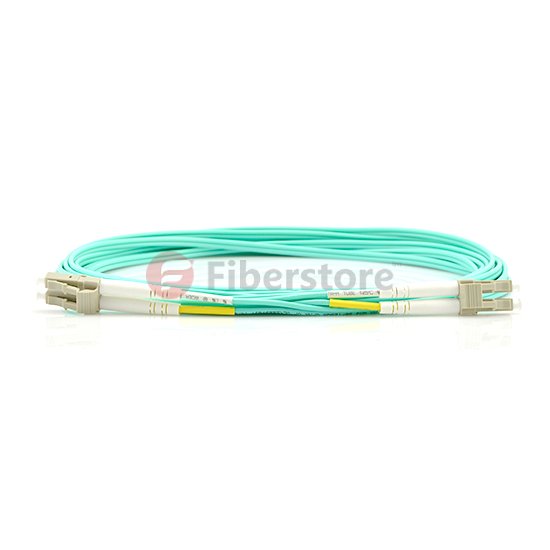
LC-LC Duplex 10G OM4 50/125 Multimode Fiber Optic Patch Cord

lc lc fiber optic patch cord

Cost-effective solution that provides higher bandwidth and transmission rates and supports longer distances with lower loss than 62.5 fiber. Specifically designed for use with today’s narrower aperture components, this LC-LC fiber optic cable is fully compatible with multimode applications. The patented injection molding process provides each connection greater durability in resisting pulls, strains, and impacts from cabling install.

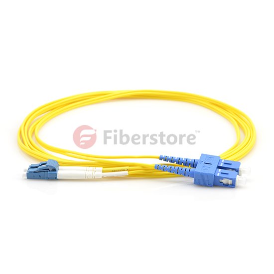
LC-SC Duplex 9/125 Single-mode Fiber Optic Patch Cord

lc sc fiber optic patch cord

● LC-SC Connectors
● Singlemode Duplex fiber optic cable
● Micron: 9/125um
● Complete with Lucent Technologies aqua jacket
● Bandwidth transmitting rates up to 10 gigabits
● All of our fiber optic patch cables feature the high degree connectors
● 100% optically tested to ensure high performance
● Color: Yellow

SC fiber cable is one of the earliest types and one of the most commonly used fiber optic cable, it is convenient to use and cost saving – It is the cheapest type fiber optic cable. SC fiber patch is widely used in fiber optic networks. SC fiber patch cable is with zirconia sleeve and plastic housing.

The patch cord must incorporate exactly the same fiber as is contained within the rest of the cable plant. There is no reason why the connectors on each end need to be the same. What is important is that one end of the patch cord matches that found on the active equipment and the other end matches the patch panel.

Patch Cord Optical Power Loss Measurement

Share

Measurement of fiber optic cable loss is an established practice that has been performed for many years. However, over time, the performance of fiber optic equipment has been improved, so occasionally it is useful to perform a practical re-assessment of the accuracy of these measurements.

Multi-mode patch cord optical loss power measurement is performed using the steps described in ANSI/TIA-526-14, method A. The fiber optic patch cord is substituted for the cable plant. Because patch cords are typically no longer than 5 m, the loss for the optical fiber is negligible and testing can be performed at 850 nm or 1300 nm. The loss measured in this test is the loss for the patch cords connector pair. ANSI/TIA-568-C.3 states that the maximum loss for a connector pair is 0.75 dB.

After setting up the test equipment as described in ANSI/TIA-526-14, method A, clean and inspect the connectors at the ends of the patch cords to be tested. Verity that your test jumpers have the same optical fiber type and connectors as the patch cords you are going to test. The transmit jumper should have a mandrel wrap or modal conditioner depending on the revision ANSI/TIA-526-14 being used for testing. Ensure that there are no sharp bends in the test jumpers or patch cord during testing.

Because both patch cord connectors are easily accessible, optical power loss should be measured in both directions. The loss for the patch cord is the average of the two measurements. If the loww for the patch cord exceeds 0.75dB in either direction, the patch cord needs to be repaired or replaced.

For testing the loss of a patchcord, you only need an 850 nm LED light source for multimode cable or 1310 laser for singlemode, a fiber optic power meter and some reference patchcords. Just remember that the patchcords used for references in testing must be good for tests to be valid, so you test them as you would other patchcords, just more often.

Testing patch cords is similar to testing any fiber optic cable. Use one reference patch cord to set a 0 dB reference. Connect a patch cord to test to the reference patch cord with a mating adapter. Connect the power meter to the other end of the patch cord and measure the loss. Since the length of the fiber is short, the loss contribution of the fiber is ignoble. And since one end of the cable is attached to the power meter, not another cable, you only measure the loss of the one connection between the reference cable and the cable under test, so you can test each connector individually.

To complete the testing of the patch cord, reverse the cable you are testing to check the connector on the other end. Sometimes you will find one bad connector and can replace it to make the patch cord useful again. But often the cost of replacing the connector may be higher than replacing the patch cord itself.

If your test equipment has different connectors than the patchcords you are testing, you will need hybrid reference cables with connectors compatible with the equipment on one end and the patchcord connectors on the other end. You will also need the correct connector adapters for your power meter.

Obviously, all reference cables used for testing must have high quality connectors to get reliable test results. Use this same method to test your reference cables against each other and discard any with high losses, usually those with losses over 0.5 dB.