Tag Archives: fiber patch cord

Have You Ever Used Traceable Fiber Patch Cords?

Share

Finding patch cord connections within densely populated patching areas is always a challenge. To meet the ever-growing need to quickly and easily identify and trace network connections in today’s high-density and mission-critical infrastructure environments, traceable fiber patch cords were introduced, which offer quick and accurate method of identifying the termination point of optical patch cords. Have you ever used this fiber cable type? This article may provide some knowledge about traceable fiber patch cords.

Traceable Fiber Patch Cords Design
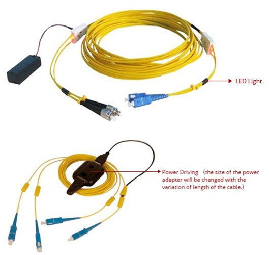
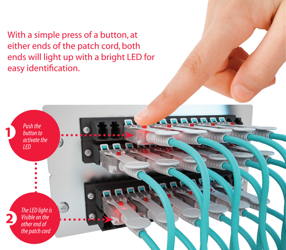
Seen from the picture below, each end of traceable fiber patch cord features a flashing LED light allowing technicians to visually trace individual patch cords from one end to another without pulling or affecting the patch cord. In terms of power driving, the size of the power adapter will be changed with the variation of length of the cable.

Traceable Fiber Patch Cord

How Do Traceable Fiber Patch Cords Work?
Traceable fiber patch cord features a LED component inside each connector end. Pushing the activation button causes the LED on both ends begin to flash rapidly, as a result, the connector on the distant end of the patch cords start reflecting the flashing light and can be quickly and easily identified without interruption of service.

Traceable Fiber Patch Cable

Traceable Fiber Patch Cords Features and Benefits
Traceable fiber patch cord is targeted toward high-density and high congestion areas of the telecommunication fiber optic network. Areas of use spans across the network where passive and active fiber management elements are located. The features and benefits of the traceable fiber patch cords are displayed in the table below.

Feature Benefit
LED indicator at both ends of jumper Visual indication of the far end of the jumper
Simple LED tool to apply power to one end of jumper to easily identify the far end of a jumper in connected area Eliminates errors due to mislabeling, missing labels or confusion in high density frames
Assemblies are available in Singlemode Bend Insensitive Fiber (BIF) and multimode OM3 and OM4 fiber types Reduced insertion loss while routing cable through congested fiber trough and tray, dense frames or between equipment
All assemblies meet TIA/EIA and IEC intermateability standards.
RoHS compliant
Reduce OPEX cost by reducing installation, maintenance and trouble shooting time
Available in a wide variety of connector types and lengths.
Custom configurations available upon request, including multiple boot styles, colors and angle options
Simplify and speed up deployment and cross connect
Eliminate errors during move and adds of fiber capacity
Simple ordering process of the right product for the application

FS.COM offers traceable fiber patch cords in 10G (OM3 and OM4) performance for 10-Gbit applications, as well as single mode or OM1 and OM2 performance for Gbit applications. FS.COM’s traceable fiber patch cords feature an integrated and exceptionally bright LED light that enables easy identification of where the cord is connected. For more information, please contact at sales@fs.com.

Frequently Asked Question About Fiber Patch Cord

Share

What Is Fiber Patch Cord?

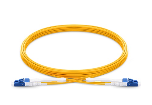
A fiber patch cord can be a cable that connects devices allowing information to pass together. Patch cords certainly are a common method of setting up wired connections between devices, including connecting a tv with a digital cable box using coaxial cable. These cords are used for any kind of signal transference, such as in a television, radio or computer network. These cables are manufactured with standard fiber optic cabling and are terminated with fiber optic connectors for both ends.

fiber patch cord

What Is Fiber Patch Cord Used for?

There are several application areas for optical fiber cable, including connecting computer workstations to outlets and connecting fiber optic patch panels or optical cross-connect distribution centers.

What Are the Most Common Fiber Optic Patch Cables?

There are lots of common forms of fiber patch cables and your network may need a number of these phones operate most efficiently. Professionals use a number of ways to categorize the most frequent fiber patch cables, like the fiber cable type, the termination connector types, the optical fiber modes, the dimensions of the fiber cable, as well as the various styles of polishing the connectors. FS.COM offer several types of common patch cable, it provides 10G OM3/OM4 fiber patch cable; 9/125 single-mode and OM2 50/125, OM1 62.5/125 multimode fiber patch cable having a number of connector types including LC, SC, ST, FC, MU, and MTRJ.

What Are Fiber Optic Cable Types?

There are the main kinds of fiber cable: Simplex, Duplex. A Simplex fiber patch cable has one fiber and one connector on each side. A Duplex fiber optic cable features two fibers and a couple connectors on both ends. Either each fiber will probably be marked separately (e.g., A and B) or the connector boots uses different colors to think the polarity of each connector.

How Are Fiber Optic Patch Cables Terminated?

You can find basically two methods to terminate a fiber cable: utilizing the same connector type on both ends from the cable (e.g., LC fiber patch cable: LC to LC) and taking advantage of two different connectors on each side from the cable (e.g. ST-SC fiber patch cable) which is also known as the Hybrid termination.

What Are the Most Common Connector Types for Fiber Patch Cord?

Typically the most popular connector types are SC, ST, LC, MTRJ, MU, and FC.

What Modes Are Utilized in Fiber Patch Cord?

Currently, there are three different modes which can be used in fiber patch cords: single mode, multimode, and 10G multimode. Single mode fiber cables count on 9/125 micron fiber cable with single mode connectors on both ends with the cable. Multimode fiber optic patch cables use 62.5/125 micron or 50/125 micron fiber cabling and therefore are terminated with multimode fiber optic connectors on each end of the cable. 10Gb multimode fiber optic patch cords use enhanced 50/125 micron fiber that is optimized for 850nm VCSEL based 10Gb Ethernet. They are usually suitable for existing network equipment and will offer 300% more bandwidth than traditional 62.5/125 multimode fibers. These cables will also be rated for distances up to 300 meters.

Why Are There Different Connector Polishing Styles?

Fiber optic connectors were created, manufactured and polished to different shapes to reduce back reflection. Back reflection grades generally vary from -30dB to -60dB. Remember that polishing is especially important for applications in which single mode fiber has been used.

What Are Other Names for Fiber Patch Cord?

This really is by no means a thorough list of synonyms of these cables, but we now have heard them called: fiber optic patch cords, fiber patch cables, fiber optic jumpers, fiber jumper cables, duplex fiber jumpers, fiber wire, LAN fiber, network fiber, optic cables, network glass, plus more.

What Information Should I Provide If I Want to Modify the Fiber Patch Cord?

The following:

1. Quantity, and Length in meters.

2. The number of fibers. Simplex or Duplex.

3. Connector type for both ends, they could ‘t be exactly the same on both ends.

4. Singlemode or Multimode fiber. If Multimode please advise if 62.5/125 or 50/125, or 50/125 laser optimized.

5. PVC or Plenum jacket.

6. It is possible to send your customized detail info to the email: sales@fs.com, our sales will contact you as soon as possible, many thanks.

Connectorized Couplings

Share

Quite often it is desirable to have a means of connecting two fibers together through a temporary mating device or connector. Figure 7.4 shows a common way to implement such a connector. Each fiber is placed in a ferrule whose function is to provide the mechanical support for the fiber and hold it in place tightly. The ferrule can be made out of plastic, metal, or ceramic materials. The central piece of the connector itself is an alignment sleeve. The two ferrules are inserted in the sleeve, and proper alignment between the cores is ensured because of the tight mechanical tolerances of the ferrules and the sleeve. The gap between the two fibers can be controlled by a mechanical stop which determines the exact stopping positions of the fibers. In some variations, the alignment sleeve is tapered to improve connector mating and demating.

Well-designed connectors provide low coupling loss, in the order of 0.1 dB or less. However, as shown in Fig. 7.5, a number of underirable situations can reduce the coupling efficiency. Figure 7.5a shows a case of two fibers with different core diameters. In general, whenver the numberical apertures of two fibers are different, the potential for power loss exists. In this case, light coupling from a narrower fiber core to a wide fiber core is easier and more efficient compared to coupling in the other direction. Figure 7.5b shows an example of poor concentricity. Fibers that do not provide a tigh concentricity tolerance may show large coupling variations depending on the orientation or from one pair of fibers to the next.

fiber connector

A large air gap, shown in Fig 7.5c, is another reason for loss of power. An air gap can result from incomplete insertion of the fiber or from mechanical problems inside the sleeve. It is also common for microscopic dust particles to get into fiber optic connector, preventing them from making proper conatact, or even scratching and damaging the fiber facets.

More dramatic power reduction results when dust particles land on the fiber core, blocking the light path. As a result, constant monitoring and cleaning of fiber facets are important to prevent such probems. Angular or lateral displacement, the mechanical tolerances are not tigh enough or when the dimensions of the sleeve and the ferrule do not match.

A fiber connector is characterized by several important parameters. As noted before, the most important factor is insertion loss, or simply connector loss. Another important factor is repeatability. If the same two fibers are connected through the same connector a number of times, each time the coupling will be slightly different. A good connector assmbly provides a small standard deviation for coupling efficiency across multiple insertions. Another desiralbe specification of a fiber connector is low return loss, i.e., a low back reflection. Return loss is defined as the ratio of the reflected power from the connector to the input power. For example, a return loss f 30 dB means 0.001 of the input power is reflected back from the connector. A conector must also be resistant and show a minimal coupling variation in the presence of normal mechanical forces such as axial and lateral forces. This is a practical requirement because in a normal environment it is likely for the connector to encounter a range of mechanical forces.

A wide range of connectors have been designed and are in use in the industry. Here we give an overview of some of the most popular types.

Straight tip or ST connectors are one of the more common type of connectors and in wide use in many applications. The ferrule diameter in an ST connector is 2.5 mm. ST connectors are spring loaded and enaged by a twist-and-lock mechanism.

Fixed connector or FC connectors use an alignment key and a threaded (screw-on) socket and are similar to the popular SMA connectors used in electronics. They are in wide use in single-mode applications and provide low insertion loss and high repeatability.

Subscriber connector, or SC, is another common type of connector. The advantage of SC connectors is that they are engaged by a push-and-snap mechanism, without the need for any roation. This make plugging and unplugging them very easy and also reduces wear out. Moreover, a higher connector density is achieved. Many transceivers provide either an SC receptacle connector, or a pigtail SC connector, as their optical interface. The push-and-snap feature of SC connectors thus provides very convenient and easy way of connecting to optical trasceivers. SC connectors are avaiable in simplex and duplex variations. The ferrule diameter in an SC connector is 2.5 mm.

SC fiber optic patch cable is one of the earliest stype and one of the most commonly used fiber optic cable, it is convenient to use and cost saving, SC fiber optic patch cord is widely uesed in fiber optic networks. SC fiber patch cable is with zirconia sleeve and plastic housing. The common type of SC connector patch cord, there are SC to SC fiber patch cord,  SC to LC Fiber Optic Patch Cable, SC to ST Fiber Optic Patch Cable,  SC to FC Fiber Optic Patch Cable, ect.

The LC or small form factor connector is similar to the SC, but with half the size. The diameter of the ferrule in an LC connector is 1.25 mm, vs 2.5 mm for most other connectors. This allow for twice the connector density for a given space. Because of their compactness, LC connectors have become more popular and are used in many high-end transceivers such as SFPs and XFPs.  LC fiber optic patch cable is with a small form factor (SFF) connector and is ideal for high density applications. LC fiber optic patch cord connector has a zirconia ceramic ferrule measuring 1.25mm O.D. with a PC or APC endface, and provides optimum insertion and return loss.

Related Article:  Which Patch Cable Should I Choose for My Optical Transceiver?

Maintaining Polarity In Modular Fiber Optic Cassette-Based Cabling

Share

Introduction

Data centers are the central location for data interchange and are found in enterprises, government offices, schools, universities, hospitals, and other networked server farms. The ease of turning nearly any location into an information interchange hub has been enabled by the development of array-based fiber optic cabling systems. Ribbon fiber cables, array-based fiber connectors, and packaged breakout assemblies like fiber optic cassette provides modular small form factor connectivity and enable fast, reliable interconnection of fiber optic links in high-density data center environments.

Once the decision has been made to deploy array-based fiber connectivity, care must be taken to ensure the integrity of connections between the transmitting optical light source and the receiving photo detector. The matching of the transmit signal (Tx) to the receive equipment (Rx) at both ends of the fiber optic link is referred to as polarity. The objective of polarity is simple: provide transmit-to-receive connections across the entire fiber optic system in a consistent, standards-based manner.

Preterminated fiber MTP MPO optical cassettes and loose-tube or ribbon fiber backbone cables are the heart of a modular fiber system. The cassettes and cables typically support groups of full-duplex fiber connections. The challenge for the network system designer becomes one of assuring the proper polarity of these array connections from end to end.

This white paper describes the methods defined in the ratified TIA/EIA (Telecommunications Industry Association/Electronic Industries Association) standard to assure correct polarity using MPO multi-fiber array connectors, cables and cassettes.

Standards and methods:

The TR-42.8 Technical Engineering Subcommittee has developed a standard that addresses the polarity issues associated with multi-fiber array connections. (This document, TIA-568-B.1-7, is available through the Internet for purchase as a reference document.)

Currently, a new release of the TIA-568 Commercial Building Cabling Standard is under development as the TIA-568-C series of standards. The fiber-systems section of this series will be TIA-568-C.1, and will include information on array system polarity along with a description of MPO array cables, duplex patch cords, and array transitions.

Modular fiber optic cassettes:

Modular fiber optic cassettes-enclosed units containing 12- or 24-fiber factory-terminated fanouts-serve to transition small-diameter ribbon cables terminated with an MPO connector to the more-common LC or SC interfaces used on the transceiver terminal equipment. The fanouts typically incorporate SC, LC, ST-style or MT-RJ connectors plugged into adapters on the cassette’s front, and an MPO connector plugged into an MPO adapter on the cassette’s rear side.

One or more MPO fanout assemblies may be installed inside the fiber optic cassette to connect up to two, 12-fiber ribbon cables, for a total of 24 fibers. Alignment pins that are preinstalled in the MPO connector within the cassette precisely align the mating fibers in the MPO conn

ectors at either end of the array cables that plug into the cassettes.
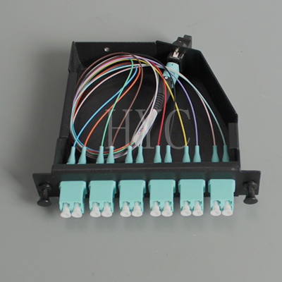
MPO Cassette

The transition that takes place inside a fiber optic cassette, the connector keying for the cassette and the corresponding MPO array cables are all thoroughly defined for all three connectivity methods listed in the TIA standard. A common transition, factory-installed inside a cassette, is used for all three methods. The adapter mounted at the rear of a cassette defines it as either a Method A or Method B type. The only difference between the two cassette types is the orientation of the internal MPO connector with respect to the mating MPO array cable connector.

Method A cassettes make a “key up”-to-“key down” connection between the internal MPO connector and the MPO array cable connector. Method B cassettes make a “key up”-to-“key up” connection. It is important to note that a Method B cassette will not allow single mode angle-polish mated-pair connection because the angles of the mating connectors are not complementary. This prevents a Method B cassette or adapter from being used in single mode applications that require low return losses-a significant limitation.

MPO array cables:

Modular fiber optic cassettes are connected to one another with MPO to MPO ribbon backbone cables. The connectors on these cables do not contain alignment pins, but they do have mating alignment holes. Alignment pins are factory-installed in the MPO fanout connectors installed inside the fiber optic cassette.
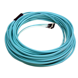
MTP MPO fiber cables

The TIA standard defines three different 12-fiber MPO cable: Types A, B, and C. Each is used for its respective connectivity method (Methods A, B, and C).

For the Type, A array cable, the opposing connections at each end of the cable have the same fiber positions, except that one end has the key oriented facing up while the other end has the key oriented facing down.
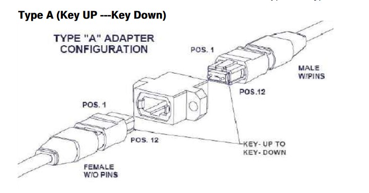
MPO to MPO

The Type B array cable has opposing connectors with both keys oriented facing up, but the fiber positions are reversed at each end; the fiber at position 1 at one end is connected to position 12 in the connector at the opposing end.
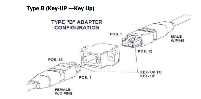
MPO to MPO Fiber

In the Type C array cable, the key is facing up at one end and facing down at the other end. It looks like a Type-A array cable, but the Type-C cable is designed such that adjacent pairs of fibers are crossed from one end to the other. In this case, the fiber at position 1 on one end of the cable is shifted to position 2 at the other end of the cable. The fiber at position 2 on one end is shifted to position 1 at the opposite end, and so on.

Connectivity methods:

The fiber patch cord, cassette (transition) and array cable previously described are used in specific combinations to form end-to-end full-duplex fiber links. Each component of the total fiber cabling system is unique, underscoring the importance of assuring that the correct component is selected and used in the proper sequence.

Importantly, regardless of which method defined in the TIA standard you use, there must be a pair-wise flipping (A-to-B polarity swap) that takes place at some point in the link. If the pair-wise flipping does not occur in the cassette (transition), then the pair-wise flipping must occur in the duplex patch cord, or in the MPO-to-MPO array cables and/or adapters.

Conclusions:

Modular fiber optic cassette-based cabling technology offers many advantages facilitating high-performance, rapid, and error-free installation, as well as reliable, robust operation. The best way to maintain correct optical polarity in these systems is to select a standards-based approach and to adhere to it throughout an installation. The three connectivity methods defined in the TIA/EIA-56-B.1-7 standard present the guidelines for maintaining polarity using array connections.

It is in the best interest of the installer and end-user to select modular fiber optic cassette-based solutions that adhere to TIA standards. Proprietary non-standards-based solutions will not assure interoperability. In addition, those solutions may not be compatible with commercially based components designed to meet the TIA standards. Selecting modular fiber systems that comply with TIA standards can help to prevent costly troubleshooting and rework of the installed fiber cable plant. Additionally, fiber-network installers can be assured of a readily available product supply from multiple stocking supply sources with acceptable delivery lead times.
The Specific Instructions of Optical Fiber Patch Cord

Share

Optical fiber communication refers to modulate voice, video and data signals to the fiber patch cord as a communication transmission medium. The optical fiber can be divided into multimode fiber and single mode fiber.

Single Mode Fiber Patch Cord

The central glass core of single mode fiber is fine (core diameter is usually 9 or 10μm), it only can transfer one mode light. The mode dispersion is small, and it is for remote communication, but it plays a major role in the chromatic dispersion so that the spectral width of the single mode fiber has a higher light stability and the requirement that the spectral width is narrower and better stability. 1000 Mb/s fiber optic transmission distance is 550m-100km. As we all know, we commonly see 9/125μm single mode optical fiber in the market. And single mode 9/125um fiber optic patch cables are recommended for Fast, Gigabit, 10G Ethernet or SONET OC3-OC192 rate optical connections. Low prices make the 9/125um fiber attractive for in-building projects too, because of the reliability and choice of using a single-strand of fiber for same communications (simplex cords are used on Bi-Directional data links).

Multimode Fiber Patch Cord

The central glass core of Multimode fiber is coarse (50 or 62.5μm), multiple modes of light can pass. However, its mode dispersion is among large, which limits the frequency of the transmitted digital signal, and with the increase in distance will be more severe. Multi-mode fiber transmission distance is relatively recent, generally only a few kilometers. 1000 Mb/s fiber optic transmission distance is 220m-550m. In general, we can find 62.5/125um Multi-mode fiber optic cable in the market. 62.5/125um multimode fiber cables are recommended for Fast Ethernet and up to OC3/STM1 rate optical connections. They can also be used for Gigabit Ethernet multi-mode connections on distances less than 275 meters. 62.5/125um fiber is most used inside buildings.

Types of Fiber Patch Cord

In the network wiring, the more applications optic fiber has three types, there are 62.5μm/125μm multimode fiber, 50μm/125μm multimode fiber, and 9μm/125μm single mode fiber. According to the rate and transmission distance, we can distinguish and choose single/multimode optic fiber. Tied the fiber bundle, outside has the protective housing, which is called fiber cable. According to different application environments, the cable can be divided into indoor and outdoor fiber optic cable.

Fiber refers that the fiber jumper with a desktop computer or device connected directly to facilitate the connection and manage the device. Fiber jumpers are also divided into two multimode and single-mode, which are connected with single mode and multimode fiber. Jumper for an active connection cable between the two devices without connectors (as distinguished: patch (patch cord) is one or both ends with connectors; jumper is at both ends of the cable has a fiber optic connectors, the device can be directly connected, but only one end of the fiber pigtail connector and the other end to the fiber splicing).

Fiber Patch Cord Connector Types

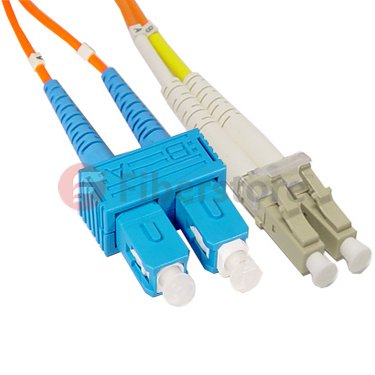
Fiber patch cord connector shape can be divided into FC, SC, ST, LC, etc. According TO ferrule grinding mode, it can be divided into PC (plane), UPC (spherical surface), APC (8 degrees inclined plane ) and other (cable optical transceiver general requirements FC / APC connector). According to the type of optical fiber, it can be divided into the single mode optical fiber, 50/125 multimode, 62.5/125 multimode and Gigabit, etc. According to the optical fiber connetor, we commonly see LC, SC fiber patch cord in the market,  the following products are LC-SC fiber in our online store, if you have interest, you can go to our store to have a see.

LC SC Fiber patch cord

Fiber patch cord products are widely applied, it applies in the communications room, fiber to the home, local area networks, fiber optic sensors, fiber optic communication systems, fiber optic transmission equipment connected, defense readiness and so on. Apply to cable television, telecommunications networks, computer networks and optical fiber test equipment. Broken down mainly used in several ways.

Using Fiber Optic Power Meter to Test Optic Power Level

Share

Fiber optic communication equipment is based on the optical power level between the transmitter and the receiver. The difference of the optical power level between them is the loss of the cabling plant. To measure the power loss of them, an optical power meter is needed to conduct a power loss testing.

fiber optic power meter is typically consist of a solid state detector, signal conditioning circuitry and a digital display of power. To interface to the large variety of fiber optic connectors in use, some form of removable connector adapter is usually provided. The power meter is calibrated at the same wavelength at the source output such as multimode 850 or 1300nm, single mode, 1310, 1490 and/or 1550nm, POF. Meters for POF systems are usually calibrated at 650 and 850nm. The wavelengths used in POF systems.

When performing the test, use the optical power meter adapter to mate to the connector type on the cable. The connectorized reference patch cables must be the same fiber type and size as the cable plant and have connectors compatible to those on the source and cables.

Power meters are calibrated to read in dB reference to one milliwatt of optical power. Some meters of a relative dB scale also, useful for loss measurements since the reference value may be set to 0 dB on the output of the test source. Occasionally, lab meters may also measure in linear units like milliwatts, microwatts and nanowatts.

Optical Power Testing Procedure:
Turn on the power meter to allow time to warm-up.
Set meter to wavelength of the source and “dBm” to measure calibrated optical power.
Clean all connectors and mating adapters.
Attach reference cable or fiber patch cord to source if testing source power or disconnect cable from receiver.
Attach power meter to end of cable and read measured power.

To reduce the measurement uncertainty, you must calibrate the optical power meter according the manufacturers specified intervals. Clean all connectors and remove the meter adapter periodically to clean the adapters and power meter detector. To avoid the stress loss, please don’t bend the fiber optic cables during the testing.

Optic power testing is only one the main part of fiber optic testing. Most test procedures for fiber optic component specifications have been standardized by national and international standards which are converted in procedures for measuring absolute optical power, cable and connector loss and the effects of many environment factors such as temperature, pressure, flexing, etc. Basice fiber optic testing instruments are the fiber optic power meter, optical light source, OTDR and fiber inspection microscope.

Fiber Optical Faceplate Wiki

Share

A fiber optic face plate is a coherent multi-fiber plate, which acts as a zero-depth window, transferring an image pixel by pixel (fiber to fiber) from one face of the plate to the other. Fiber optic faceplates can be applied in FTTH access network, telecommunication networks, CATV networks, data communication networks, which is used to bring fiber to the desk and can be widely used in multi-floor and high buildings. The fiber optic faceplate can be sometime called fiber wall jacks which are available with LC. SC, ST, FC fiber optic adapters, the port number is usually 2, 3 or 4 ports.

Generally, fiber optic wall plates can be divided into three types which is bevel fiber optic plate, hybrid fiber faceplate, FTTH fiber faceplate:

The bevel fiber wall plate is with 45 adapter plug- in/out angle, Hybrid fiber optic faceplate means the fiber adapter types are different from each other which can be SC-ST, SC-ST-LC, or
SC/ST/FC/LC, each adapter style is for one port.

Common Features of bevel fiber wall plate and hybrid fiber optic faceplate includes:
Size is 86*86mm
ABS plastic material
No additional insertion loss, simple operation, low construction intensity
The snap-in module is easy to install with straight tip style fiber optic connector
All fiber adapters are “universal” to support either multimode or single mode fiber connectors

Application:
FTTH access network
Telecommunication Networks
CATV Networks
Data communications networks

Except these two types, there is also another type which is the FTTH fiber optic faceplate, which is mainly designed for applications of FTTH, FTTB, FTTC, telecommunication networks and CATV4,Local area network. Check out some features of these FTTH fiber optic faceplate.
Indoor or outdoor rated
Available in 1×4, 1×8, 1×16 splitter as well as 2×4, 2×8, 2×16 splitter
Max. Up 16pcs of FTTH drop cable or pigtails
Suitable for wall-mounting or pole mounting application

Fiber wall plate is also used to create a fiber optic network at home. Besides the switches between different floor, fiber wall plate/jack and the pre-terminated fibers are needed. Look at the specs for the optical port on the switch. If the optical port is a pluggable device, you need to get its P/N and look up the spec. Most of the fiber sold on FiberStore that is conecterized, is patch chords. Fiber patch cord has very little strain relief in them. So take care when you pull them in your new installation that you do not damage them.