Category Archives: Fiber Patch Cord

One LC Switchable Uniboot Cable Removes All Your Problem

Share

Suppose that you need some LC fiber patch cords to build a data center and now there are common LC patch cable and LC switchable unibboot cable. What kind of cable will you choose? Considering the cost, you may select common LC patch cords. But think about that for a while, you may make the different choice. Let’s see why you need LC switchable uniboot cable.

LC Switchable Uniboot Cable: Switch Polarity Easily and Quickly

Have you ever changed polarity when running fiber patch cords? How long did you spend on finishing that? Did you make any mistake? Polarity is quite a complicated thing. Engineers must be very careful to ensure that the transmit signal (Tx) at one side should match the corresponding receiver (Rx) at the other side. If polarities don’t match, signal transmission may get impacted. Then how to do polarity conversion in an easy and quick way? LC switchable uniboot cable is your option.

duplex-cords-polarity

LC Switchable Uniboot Cable Help You Do Easy Polarity Conversion

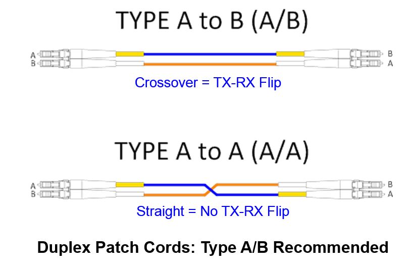
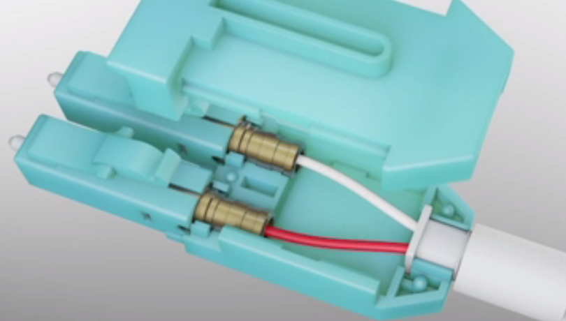
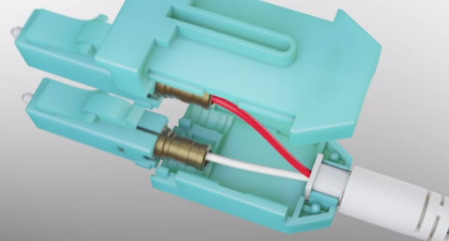
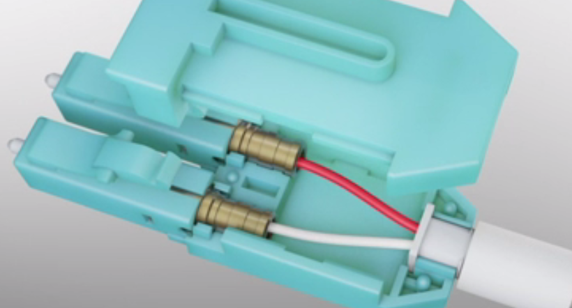
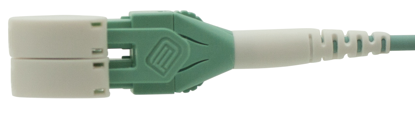
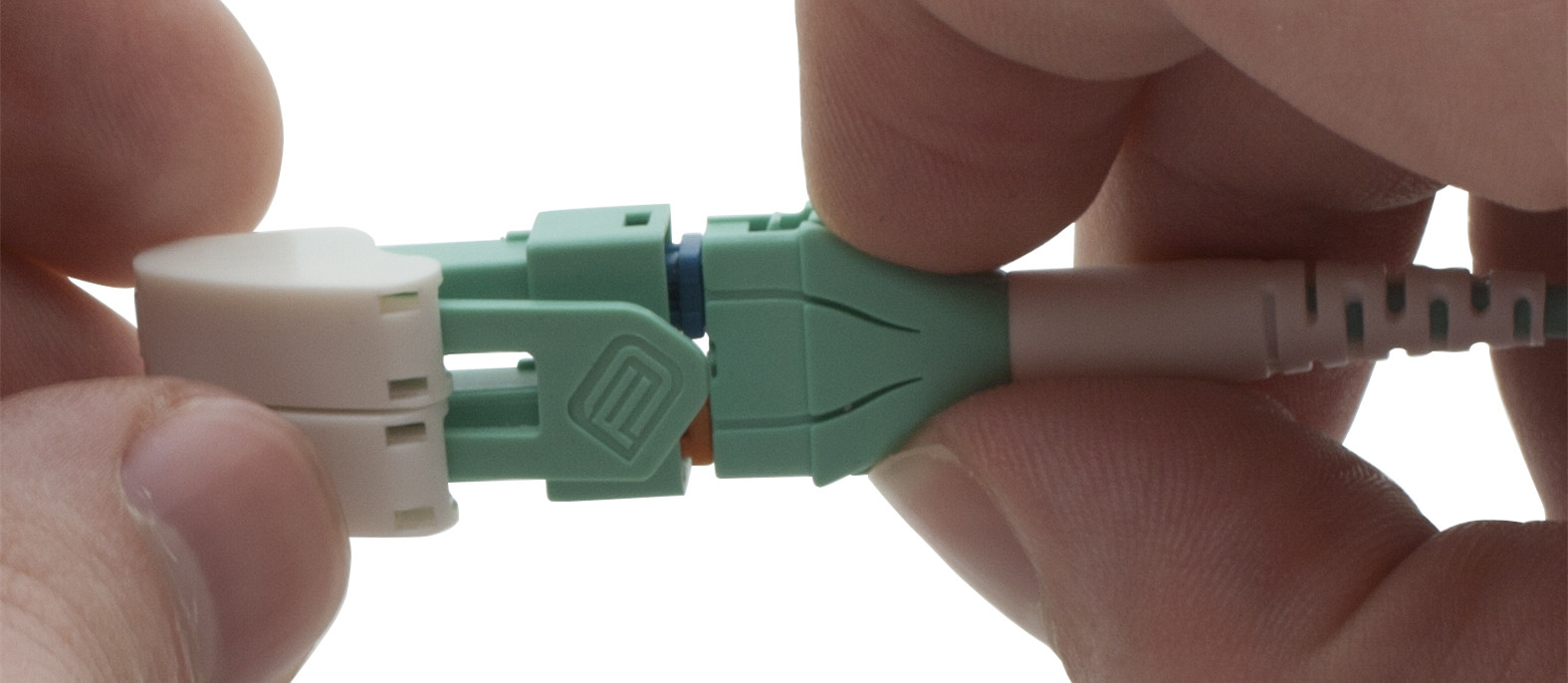
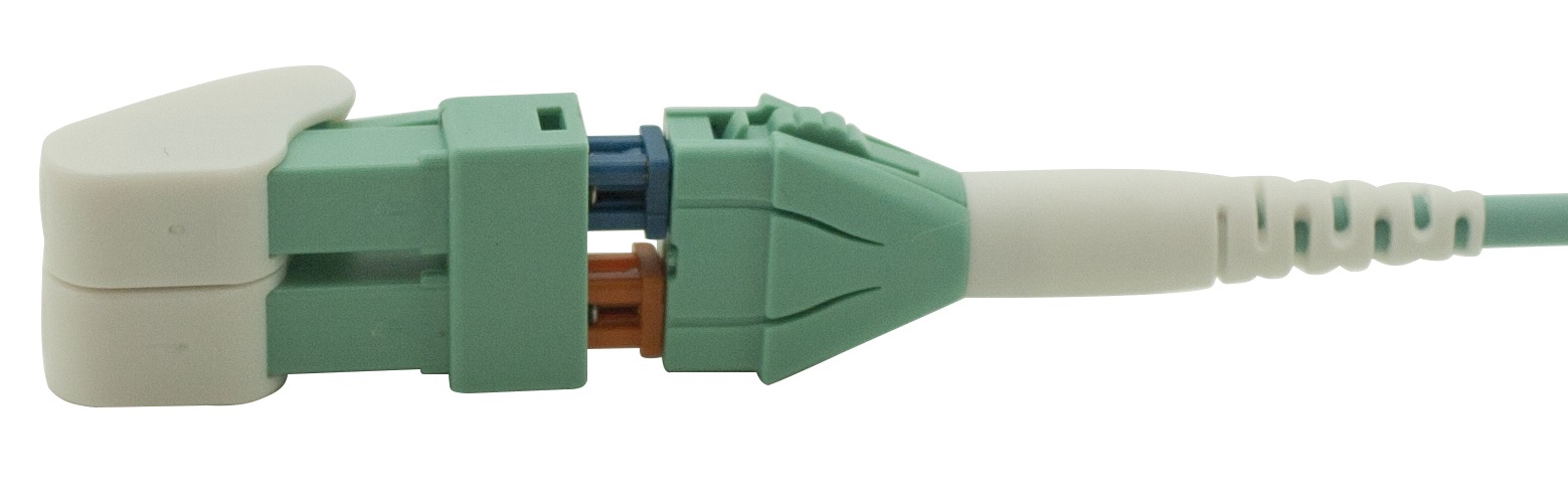
We all know that polarity conversion of traditional LC cables would require to re-terminate connector. It takes much time and leads mistakes. What’s more, you need special tool to finish that process. Unlike common LC patch cords, this switchable uniboot cable supports the polarity to be switched without connector re-termination. Polarity changes can be made in the field quickly, without the use of tools, to the correct fiber mapping polarity. No damage to fiber.

lc switchable uniboot cable

How to Reverse the Polarity of LC Switchable Uniboot Cable?

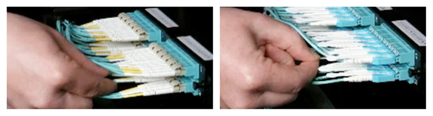
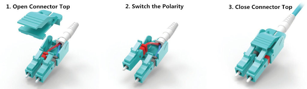
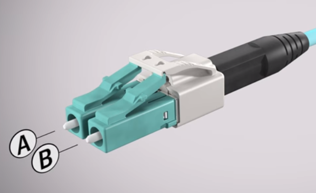
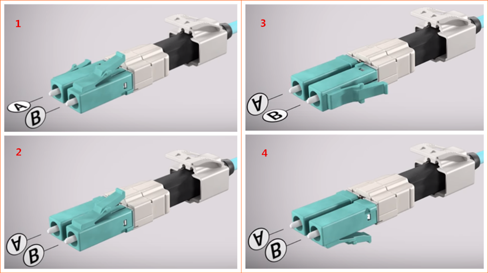
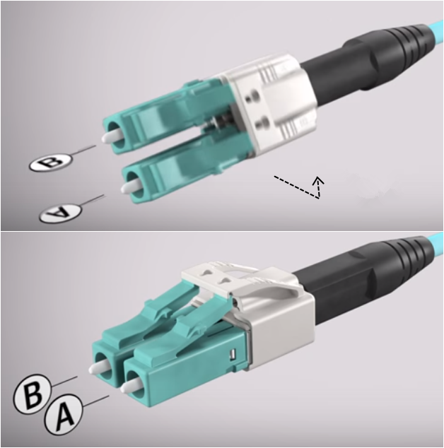
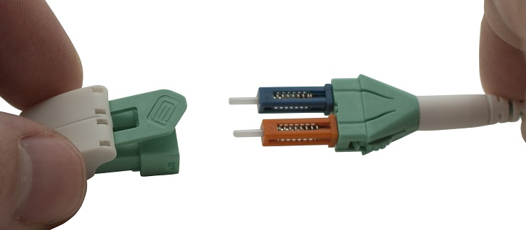
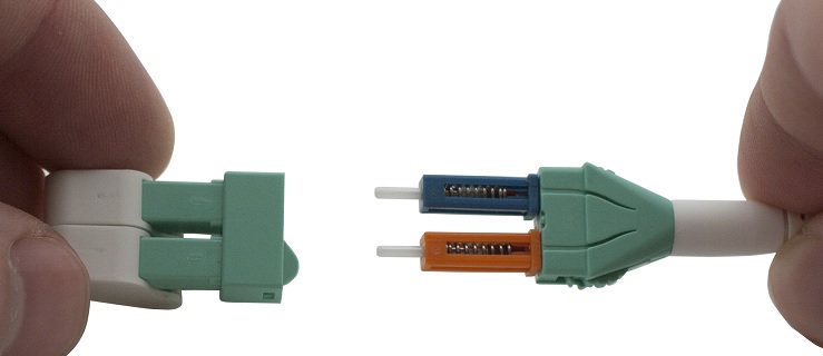
To reverse polarity, you just need three steps. First, open the connector top. Second, switch the polarity you need. At last, close the connector top. No tools are needed during the whole process. Isn’t the LC switchable uniboot cable a good choice?

lc-switchable-uniboot-polarity

LC Switchable Uniboot Cable Is Good for Saving Space and Cooling

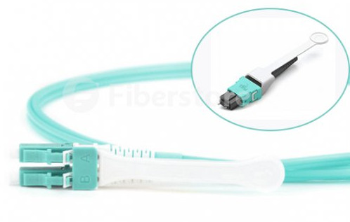
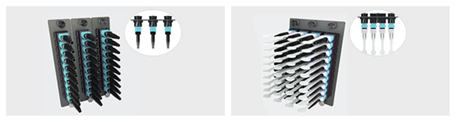
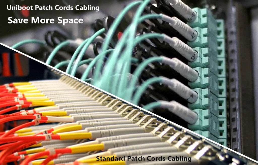
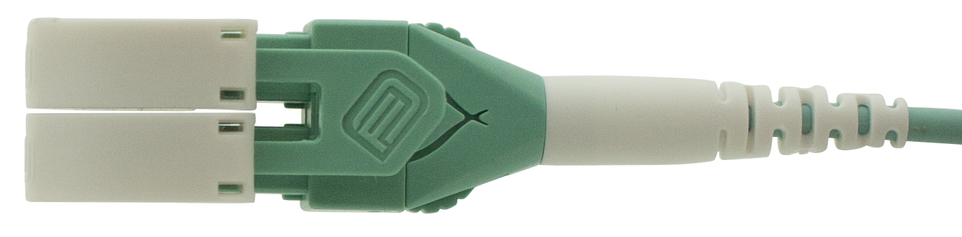
Except the polarity issue, engineers may come across the problem of limited space and airflow when building infrastructure in high density data center. How to deal with that? Switchable uniboot cable is absolutely a good choice. The cable is designed as round style of 2mm jacked cables instead of zipcord duplex cables, reducing cable size and increasing 60% density. So switchable uniboot cable is beneficial for saving space and cooling.

lc-uniboot-vs-standard

What Should Notice When Buying LC Switchable Uniboot Cable?

LC switchable uniboot cable is helpful to simplify switching polarity, save space, which is an ideal solution for high density data center. In case that you need, here are some suggestions for you When buying LC switchable unibboot cable.

  • 1. Connector is an essential factor. If the connector has a poor quality, it can cause optical loss. You are suggested to choose Senko connector which is famous for its high quality.
  • 2. For patch cords, the other important factor is fiber. As we know bending sometimes inevitable. Corning fiber is outstanding for its bending insensitivity. For single mode fiber, the minimum bend radius is 10mm. For multimode fiber, the minimum bend radius is 7.5mm.
  • 3. Pay attention to insertion loss (IL) and return loss (RL) for single mode and multimode cable.
  • 4. Find if the cable meets various standards, for instance, CE, IEC, ROSH, EIA/TIA, Telecocordia GR-326-CORE standards.
  • 5. LC uniboot patch cable price is of course another point you care much. So find several uniboot lc cable manufacturers to compare the price and choose the one you accept.

Related Article: LC Fiber Connector, Adapter and Cable Assemblies

Change Polarity in a Hurry? Try Polarity Switchable LC Cable!


How to Build a 10G Home Fiber Network?

Share

The network has become the lifeblood for home and small business. It changes the way we live, work and communicate. Nobody today would deny the importance of the network, while it keeps evolving to satisfy the requirement of people. 10G home fiber network, in this case, are no longer restricted to use in small and middle-sized business. It’s not uncommon for home to start with a 10G network setup. So how to get 10G home network? You may find some clues in this article.

Begin with Needs Assessment

Pretty much everything nowadays rely on a fast and reliable network, which leads to tremendous traffic and applications running on the networks and it keeps growing at high pace. Deploying 10G home fiber network at home eliminates network congestion at busy times while improves your productivity.   Better planning before deployment to ensuring your network can handle your business needs. You should ask yourself a few questions, such as how many computers, printers and other peripherals will connect to your network? How much wireless coverage will you need at your location? What type of mobile devices will need access to your network?

10g-home-network-needs-assessment

What Makes a 10G Home Fiber Network?

10G Ethernet makes streaming and sharing files over local network much faster. And 10GBASE-T standard is going mainstream into the consumer segment thanks to its lower power consumption and compatibility with existing infrastructure.

10g home fiber network

To build a 10G home fiber network, several components are indispensable: 10G core switches, access switches with 10G uplinks, and 10G network interface cards for servers and storage devices. The past few years had witness the price dropping of 10G network switches. For example, the cost of Ubiquiti Unifi and Eageswitch switches are only $200. And FS 10G network switch like S3800-48T4S only cost $480 by offering 48 100/1000Base-T and 4 10GE SFP+. When it comes to access switches with 10G uplink, FS S3800 series switches offers 24 ports with 4 10G uplinks at very decent price. These switches are well suited for home network use.

S3900 series switches

What About 10G Cabling – 10GBASE-T, DAC or SFP+?

Upgrading the existing 1G network to 10G can be simple. As 10G switches also support 10GBASE-T, you can use the same RJ45 network cable to connect the 10G switch with your servers, storage and some other switches. The only difference is to use Cat6a network cable instead of Cat5e and Cat6 cable, or choose SFP+ 10GBASE-T modules with 2.5W power consumption and a maximum distance of 30 m.

For 10G switch that support 10G SFP+, you should use these ports if you have devices that come with 10G SFP+ port, or you need a 10G connection to other switches over 100m away. SFP+ ports look just the same as SFP ports on your Gigabit switches, but they’re now running at 10 Gigabit. For servers or storage devices with 10G SFP+ port, the most cost efficient way to connect is to use 10G DAC (direct attach twinax cable). These are basically copper cables with SFP+ connector on both sides, and they come in various lengths.

10g-dac-cable

To connect switches over 100 m apart, a pair of SFP+ modules and the matching fiber cable are needed between them. Depending on the length required in home network, you can use 10G optics such as 10GBASE SR SFP module and multimode fiber to reach 300 meters. FS offers a wide range of 10G SFP+ modules and fiber patch cables for short and long distance transmission.

Conclusion

This article presents you some basic facts about 10 Gigabit Ethernet and how you can build a home network over 10 Gigabit. FS provides comprehensive 10G solutions: all the components mentioned to build a 10G home network are available at FS.COM, including Cat6a Ethernet cables, fiber patch cables, DACs and 10G SFP+ modules. For more details, please visit www.fs.com.

Related Article:

Comparison Between 10Gb Switch Under $550

How to Get 10Gbps Home Network for Less Than $60?

Wideband Multimode Fiber: What to Expect From It?

Share

Multimode fiber (MMF) holds a major position in local area network (LAN) backbone cabling and data center due to its capability to transmit high data rates at relatively low cost. MMF has evolved now to support multi-gigabit transmission using 850 nm VCSEL (vertical cavity surface emitting laser) sources, and the channel capacity of which is greatly improved with the use of parallel transmission over multiple strands of fiber. Wideband multimode fiber (WBMMF), known as OM5, lately comes into our horizon as an alternative to support the escalating data rate and higher bandwidth. Then what can we expect from using WBMMF? This article may give you some hints.

Existing Problems of Multimode Fiber

OM1 and OM2 MMF are developed with the intention to support Fast Ethernet, which fail to support 10 Gbps and 25 Gbps data transmission rates. Hence they are not suggested for new installations. Laser-optimized OM3 and OM4 MMF now play a dominant role in 10G, 40G and 100G Ethernet cabling. However, the demand for bandwidth accelerates so fast, and the VCSEL-based transceiver technology cannot keep pace. Consequently, it’s getting more costly for fiber cabling systems to support next-generation Ethernet migration.

Wideband Multimode Fiber: Taking New Wavelength to Multimode Fiber

Wideband multimode fiber (WBMMF) is designed to carry multiple short wavelength signals that can be aggregated for high bandwidth applications–—a technology known as wavelength division multiplexing (WDM). Unlike conventional multimode fiber that optimally supports a single wavelength, WBMMF can accommodate multiple wavelengths, enabling these multiple wavelengths to simultaneously travel along a single fiber strand.

wideband multimode fiber

In this way, wideband multimode fiber increases each fiber’s capacity by at least a factor of four, allowing at least a fourfold data-rate increase, or a fourfold reduction in the number of fibers. That means, when transmitting four optical signals, instead of using four separate fibers, WBMMF can send down these signals on one fiber over four separate operating windows. For example, 400GbE could be accomplished with 4Tx and 4Rx fibers (today 400GbE over multimode requires 16Tx and 16Rx fibers).

Highlights of Wideband Multimode Fiber

So, what makes wideband multimode fiber standing out from other multimode fibers? Besides that it increases MMF’s utility and extends MMF’s value to customers, WBMMF also has the following advantages:

    • Wideband multimode fiber can support wavelength division multiplexing (WDM) across the 840-953nm wavelength range, at 30nm intervals.

WBMMF wavelength

  • The fiber geometry of WBMMF stays the same as existing OM4 fibers, therefore it is backward compatible with OM4 multimode fiber at 850 nm, making it feasible to retain legacy application support of OM4.
  • Wideband multimode fiber reduces fiber count by a faction of four, but increases capacity to over 100 Gb/s per fiber, enabling Ethernet 100G-SR, 400G-SR4, 1600G-SR16 and Fiber Channel 128G-SWDM4.
Applications of Wideband Multimode Fiber: Short Wavelength Division Multiplexing (SWDM)

Wideband multimode fiber provides better performance for applications using WDM technology. As the parallel multimode fiber MPO cabling is considerably more costly than the multimode fiber LC-duplex patch cord, WBMMF made it possible to use a single pair of LC fiber instead of MPO trunks in direct point-to-point connection. Which helps to reduce fiber count by transmitting multiple wavelengths in the same multimode fiber, and to keep the overall cabling costs to the minimum.

WBMMF and SWDM

Conclusion

Wideband multimode fiber is a reliable medium to expand your data center or enhance network capacity. With the capability of managing multiple wavelengths, it effectively reduces the number of fibers and enhances total channel capacity, proven to be a cost-effective solution for increasing network bandwidth, and to keep pace with the escalating data demands.

Related Article: WBMMF – Next Generation Duplex Multimode Fiber in the Data Center

Three Kinds of Polarity Reversal Methods of LC Uniboot Patch Cords

Share

As the networking environment of today becomes increasingly dependent on high-speed and high-density solutions, effective cable management is a real problem. The challenge is how to manage more cables in a smaller amount of space. The LC uniboot patch cord utilises a special “round duplex” cable that allows duplex transmission within a single 2.4mm or 3.0mm cable, which reduces cable management space by up to 70% comparing to standard LC patch cords. Besides, it has a unique polarity reversal design allows the fiber polarity to be easily switched without the use of any tools. In today’s LC uniboot patch cords market, there are usually three methods to reverse the polarity.

Method One
1. Open connector top.

11
2. Switch the polarity.

22
3. Close connector top.

33

Method Two
1. Locate trigger housing on LC uniboot connector and pull towards the boot.

1
2. Open trigger housing is resting on the boot turn each LC connector to the outside 180 degrees one at a time.

888
3. Complete the polarity reversal by turning the resting trigger housing 180 degrees around boot and click into LC until you hear a click.

000

Method Three
1. Connector Polarity
Uncrossed lines under the connector latch on the housing at both ends indicates uncrossed fiber polarity A-B/B-A.

1
2. Unlock Front Housing on One End
Push the keys on either side to unlock the housing to remove the front section of the Uniboot housing.

2

3. Remove Front Housing
Slide the front housing away from the rest of the Uniboot.

3
4. Rotate Front Housing
Flip the released section of the housing. Do not rotate or twist the fiber.

4
5. Attach Front Housing
Push the housing back over the ends and the rest of the Uniboot connector until it clicks back into place.

5
6. Connector Polarity
Finished result should now show crossed lines under the flipped connector latch and uncrossed lines on the unaltered end. This would indicate a crossed fiber polarity A-A/B-B.

6

Different kind of LC uniboot patch cords may have different polarity reversal design, therefore we must use different method to change the polarity. When you choose to use LC uniboot patch cords in your network, keep in mind to take the polarity reversal methods in to consideration. FS.COM LC uniboot patch cords (easily reverse the polarity with method one) terminated with premium grade zirconia ceramic ferrule connectors which help assure high transmission quality and low optical power loss and offer improved airflow and visibility of equipment within a high-density network environment.

Have You Ever Used Traceable Fiber Patch Cords?

Share

Finding patch cord connections within densely populated patching areas is always a challenge. To meet the ever-growing need to quickly and easily identify and trace network connections in today’s high-density and mission-critical infrastructure environments, traceable fiber patch cords were introduced, which offer quick and accurate method of identifying the termination point of optical patch cords. Have you ever used this fiber cable type? This article may provide some knowledge about traceable fiber patch cords.

Traceable Fiber Patch Cords Design
Seen from the picture below, each end of traceable fiber patch cord features a flashing LED light allowing technicians to visually trace individual patch cords from one end to another without pulling or affecting the patch cord. In terms of power driving, the size of the power adapter will be changed with the variation of length of the cable.

Traceable Fiber Patch Cord

How Do Traceable Fiber Patch Cords Work?
Traceable fiber patch cord features a LED component inside each connector end. Pushing the activation button causes the LED on both ends begin to flash rapidly, as a result, the connector on the distant end of the patch cords start reflecting the flashing light and can be quickly and easily identified without interruption of service.

Traceable Fiber Patch Cable

Traceable Fiber Patch Cords Features and Benefits
Traceable fiber patch cord is targeted toward high-density and high congestion areas of the telecommunication fiber optic network. Areas of use spans across the network where passive and active fiber management elements are located. The features and benefits of the traceable fiber patch cords are displayed in the table below.

Feature Benefit
LED indicator at both ends of jumper Visual indication of the far end of the jumper
Simple LED tool to apply power to one end of jumper to easily identify the far end of a jumper in connected area Eliminates errors due to mislabeling, missing labels or confusion in high density frames
Assemblies are available in Singlemode Bend Insensitive Fiber (BIF) and multimode OM3 and OM4 fiber types Reduced insertion loss while routing cable through congested fiber trough and tray, dense frames or between equipment
All assemblies meet TIA/EIA and IEC intermateability standards.
RoHS compliant
Reduce OPEX cost by reducing installation, maintenance and trouble shooting time
Available in a wide variety of connector types and lengths.
Custom configurations available upon request, including multiple boot styles, colors and angle options
Simplify and speed up deployment and cross connect
Eliminate errors during move and adds of fiber capacity
Simple ordering process of the right product for the application

FS.COM offers traceable fiber patch cords in 10G (OM3 and OM4) performance for 10-Gbit applications, as well as single mode or OM1 and OM2 performance for Gbit applications. FS.COM’s traceable fiber patch cords feature an integrated and exceptionally bright LED light that enables easy identification of where the cord is connected. For more information, please contact at sales@fs.com.

6 Steps Help to Choose Right Fiber Patch Cord Types

Share

There are many fiber patch cord types, such as OM1, OM2, OM3, OM4 multimode fiber and OS2 single mode fiber types. Both ends of the cable are terminated with a high performance hybrid or single type connector comprising of a SC, ST, FC, LC, MTRJ, E2000 connector in simplex and duplex. These are typically not ruggedized, depending on the application, making them suitable for internal use. How to choose right fiber patch cord types for your network? Just follow these 6 steps.

Step 1: Choose the Right Connector Type (LC/SC/ST/FC/MPO/MTP)

Different fiber patch cord types
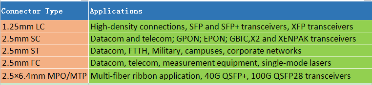
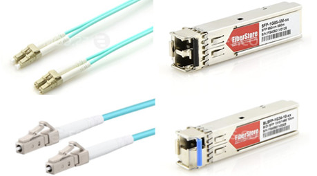
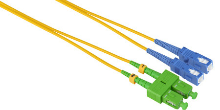
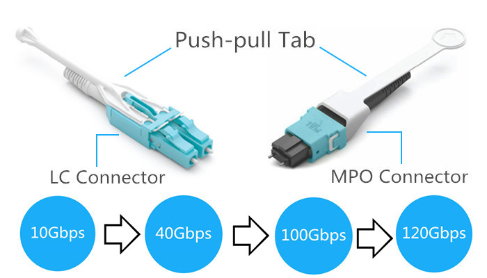
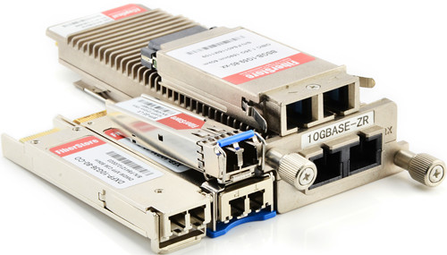
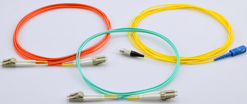
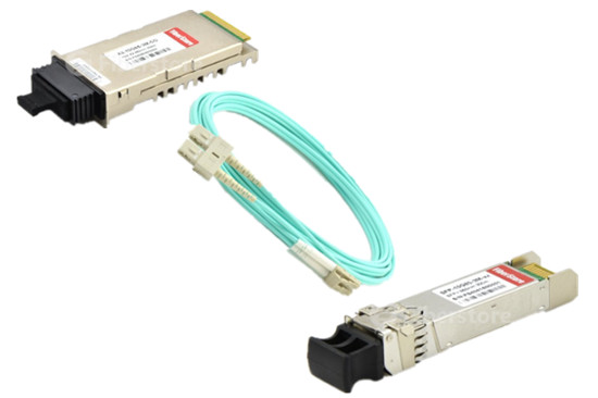
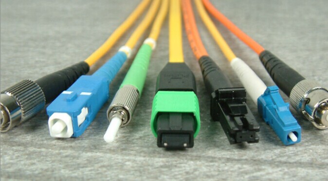
On both ends of the fiber optic patch cord are terminated with a fiber optic connector (LC/SC/ST/FC/MPO/MTP). Different connector is used to plug into different device. If ports in the both ends devices are the same, we can use such as LC-LC/SC-SC/MPO-MPO patch cables. If you want to connect different ports type devices, LC-SC/LC-ST/LC-FC patch cables may suit you.

LC SC ST FC MPO MTP fiber optic patcah cable

Step 2: Choose Single-mode or Multimode Cable Type?
Single-mode fiber patch cord uses 9/125um glass fiber, Multimode fiber patch cord uses 50/125um or 62.5/125um glass fiber. Single-mode fiber optic patch cord is used in long distance data transmission. multimode fiber optic patch cord is use in short distance transmission. Typical single-mode fiber optic patch cord used yellow fiber cable and multi mode fiber optic patch cord used orange or aqua fiber cable.

single-mode multimode fiber optic patch cable

Step 3: Fiber Patch Cord Types – Choose Simplex or Duplex?
Simplex means this fiber patch cable is with one cord, at each end is only one fiber connector, which is used for Bidirectional (BIDI) fiber optic transceivers. Duplex can be regarded as two fiber patch cable put side by side, which is used for common transceivers.

simplex duplex fiber optic patch cable

Step 4: Choose the Right Cable Length (1m/5m/10m/20m/30m/50m)
Fiber optic patch cables are made in different lengths, usually from 0.5m to 50m. You should choose an appropriate cable length according to the distance between the devices you want to connect.

Step 5: Choose the Right Connector Polish Type (UPC/APC)
Since the loss of the APC connector is lower than UPC connectors, usually, the optical performance of APC connectors is better than UPC connectors. In the current market, the APC connectors are widely used in applications such as FTTx, passive optical network (PON) and wavelength-division multiplexing (WDM) that are more sensitive to return loss. But APC connector is usually expensive than UPC connector, so you should weigh the pros and cons. With those applications that call for high precision optical fiber signaling, APC should be the first consideration, but less sensitive digital systems will perform equally well using UPC. Usually, connector color of APC patch cable is green, and of UPC patch cable is blue.

UPC APC fiber optic patch cable

Step6: Choose the Right Cable Jacket Type (PVC/LSZH/OFNP/Armored)
Usually, there are three cable jacket types: Polyvinyl Chloride (PVC), Low Smoke Zero Halogen (LSZH) and Optical Fiber Nonconductive Plenum (OFNP). You can see there features in figure below and choose the right one for your network.

PVC LSZH OFNP Fiber Optic Patch Cable
Besides the three cables mentioned above, there is another common cable—Armored Cable. The double tubing and steel sleeve construction make these patch cables completely light tight, even when bent. These cables can withstand high crushing pressures, making them suitable for running along floors and other areas where they may be stepped on. The tubing also provides excellent cutting resistance, abrasion resistance, and high tensile strength.

Armored Fiber Optic Patch Cable

FS.COM provides all kinds of fiber optic patch cables to meet demands of various customers!

Related Article:

 Common Types of Fiber Patch Cables

What Kind of Fiber Patch Cord Should I Choose?

Do You Know about Push-Pull Tab Fiber Patch Cables?

Share

More and more data centers are upgrading to 40G and beyond, which adds more floor space is an expensive, disruptive and sometimes un-affordable solution. Therefore, we should use high-density products to solve this problem. Then push-pull TAB fiber patch cables were conceived. This high-density patch cable provides improved accessibility, reduced installation costs and outstanding performance for today’s demanding high-density data center applications. In this article, some knowledge of push-pull TAB fiber patch cables will be provided.

Introduction to Push-Pull Tab Patch Cables
Push-Pull Tab Patch CablePush-pull TAB fiber patch cable is a new patch cord with a special “pull” tab design that can help to solve the problems of finger access in high-density cabling. It has the same components and internal-structure as the traditional patch cords, except a tab attached to the connector used for pushing or pulling the whole connector. With this special design, technicians can finish the installing and removing procedures with only one hand and no additional tools are needed. At present, this high-density push-pull TAB fiber patch cable, with either MPO or LC connector, is widely used in 40G and 100G network cabling.

Types of Push-Pull Tab Patch Cables
There are mainly two kinds of push-pull TAB fiber patch cables in the market: LC-HD TAB fiber patch cables and MPO-HD TAB fiber patch cables. The LC-HD TAB fiber patch cable is designed for the LC-HD switchable& movable connector. And its slim uni-boot design saves much space and makes cables more easily to be managed. MPO-HD TAB fiber patch cables can greatly simplify the use of MPO connectivity when manual access to the release slider and rear portion of the connector is restricted. In this way, easy insertion and extraction of MPO patch cords can be achieved.

push-pull-tab-patch-cords_

Advantages of Using Push-Pull Tab Patch Cables
Though traditional patch cables are popular in the data center, the push-pull TAB patch cables have many unique advantages.

  • Easy to Release Patch Cord

In high-density environment such as 48-port 1U patch panels, inserting and disconnecting patch cords can be challenging for technicians. The flexible pull-tab of the patch cable allows for the connector to be disengaged easily from loaded panels without the need for special tools. In fact, a gentle pull on the tab may disengage the connector from extremely dense fiber patch panels. Furthermore, labeling is also available on the pull-tab so that each cable can be quickly identified.

high-density Push-Pull Tab Patch Cable

  • Higher Flexibility and Adjustabilityfie

Push-pull patch cords are available in various specifications which can connect different generation of devices from 10Gb/s to 120Gbp/s or more. It provides safe and easy push and pull of the specific connector without affecting the other connectors around it. What’s more, high-density and ease of installation provide a low initial investment cost. All these benefits provide a high return on investment.

  • Space Saving

The traditional connectors often require a small vertical space above and below the adapters. While the low profile push-pull TAB patch cable, together with its pull tab, allow adapters to be stacked with absolutely no vertical space (as in the following figure).

Push-Pull Tab Patch Cables

Conclusion
We started with 1G switches. Those switches became 10G. Recently we’ve seen the trend of 40G. In the future, those switches will become 100G and even 120G. It has been proved that push-pull tab patch cords can support high durability and flexibility which fit the connection between devices of different data rate. Fiberstore offers a wide range of push-pull TAB patch cables that will help free up space.We supply simplex&duplex LC-HD patch cords, 12&24 fibers MPO-HD patch cords, MPO-LC harness cables, providing low-loss performance for multi-mode and single mode high speed networks and improving network performance.

Which SFP Fiber Cable Should I Choose for My Optical Transceiver?

Share

SFP fiber cable and fiber optic transceiver have become more and more important in fiber optic data transmission, especially in data transmission between the switches and equipment. But with so many different kinds of SFP fiber cables available in the market, which one is suitable for may optical transceiers? This article may on this issue to provide some solutions. Before starting this topic, it is necessary for us to review the basic knowledge of the fiber optic transceiver and fiber optic cable.

Fiber Optic Transceiver Overview
Fiber Optic Transceiver is a self-contained component that can both transmit and receive. Usually, it is inserted in devices such as switches, routers or network interface cards which provide one or more transceiver module slot. There are many optical transceivers types, such as SFP+ transceiver, X2 transceiver, XENPAK transceiver, XFP transceiver, SFP (Mini GBIC) transceiver, GBIC transceiver and so on.

Fiber Optic Transceiver

Fiber Optic Patch Cable Overview
Fiber optic patch cable, also known as fiber jumper or fiber optic patch cord. It is composed of a fiber optic cable terminated with different connectors on the ends. Fiber optic patch cables are used in two major application areas: computer work station to outlet and patch panels or optical cross connect distribution center. According to fiber cable mode, cable structure or connector types etc., fiber patch cable can be divided into different types.

SFP Fiber Cable

1.Single-mode and Multimode SFP fiber Cable
According cable mode, patch cables can be divided into single-mode and multimode fiber patch cable. The word mode means the transmitting mode of the fiber optic light in the fiber optic cable core. Single-mode patch cables are with 9/125 fiber glass and are yellow jacket color, while multimode patch cables are with OM1 62.5/125 or OM2 50/125 fiber glass and are orange color. In addition, there is 10G OM3 and OM4 multimode patch cables which cable jacket are usually aqua.

2.Simplex and Duplex SFP fiber Cable
Simplex fiber patch cable is consist of single fiber core, while duplex fiber patch cable is consist of two fiber cores and can be either singlemode or multimode. Additionally, there is also ribbon fan-out cable assembly (ie. one end is ribbon fiber with multi fibers and one ribbon fiber connector such as MTP connector (12 fibers), the other end is multi simplex fiber cables with connectors such as ST, SC, LC, etc.).

3.LC, SC, ST, FC, MT-RJ, E2000, MU and MPO/MTP Patch Cable
Fiber optic patch cable can be also classified by the types of fiber optic connector. For example, LC fiber optic patch cable is named as it is with LC connector. Similarly, there are SC, ST, FC, MT-RJ, E2000, MU and MPO/MTP fiber optic patch cables. What’s more, there are PC, UPC, APC type fiber patch cords, which are differentiated from the polish of fiber connectors.

Which SFP fiber Cable Should I Choose for My Fiber Optic Transceivers?
Now, I will take the Cisco fiber optic transceiver as an example to discuss this topic. For example, we need to choose a right patch cable to connect Cisco fiber optic transceiver SFP-10G-SR and X2-10GB-SR. Which patch cable to use? According to “Cisco 10-Gigabit Ethernet Transceiver Modules Compatibility Matrix”, we may know that SFP-10G-SR is the 10GBASE-SR SFP+ transceiver module for MMF, 850-nm wavelength, LC duplex connector. And X2-10GB-SR is the 10GBASE-SR X2 transceiver module for MMF, 850-nm wavelength, SC duplex connector. Obviously, this two knids of optica trancseivers are both for MMF, so we should choose a multimode patch cable. Besides, we know X2-10GB-SR is designed for SC duplex connector and the SFP-10G-SR is designed for duplex LC connector, so we should use a patch cable with SC-LC duplex connector.

Which Patch Cable Should I Choose for My Fiber Optic Transceivers

The Most Common Used SFP fiber Cable Selection
In the way mentioned above, you could choose right fiber patch cable for your other transceiver modules. Keep in mind that if your transceiver modules are not Cisco’s, you need to ask your brand supplier to get the corresponding compatibility matrix. In fact, in terms of a same kind of optical transceiver, different supplier may provide the transceiver with different specifications. Here I may list the most common used patch cables selection. Hope to give you smoe reference.

Fiber optic patch cable Applicable fiber optic transceiver connection
LC-LC Simplex 9/125 Single-mode Fiber Patch Cable 1.25Gbps 1310nmTX/1490nmRX BiDi SFP

10GBASE 1270nmTX/1330nmRX BiDi SFP+

LC-LC Duplex 9/125 Single-mode Fiber Patch Cable 1000Base-LX/LH 1310nm 10km LC SMF SFP
LC-SC Duplex 9/125 Single-mode Fiber Patch Cable Cisco X2-10GB-LR , Cisco XENPAK-10GB-LR and Cisco SFP-10G-LR
SC-LC Duplex 10G OM4 50/125 Multimode Fiber Patch Cable Cisco XENPAK-10GB-SR , Cisco X2-10GB-SR and Cisco SFP-10G-SR
LC-LC Duplex OM1 62.5/125 Multimode Fiber Patch Cable 100Base-FX 2km 1310nm MMF LC SFP
LC-LC Duplex OM2 50/125 Multimode Fiber Patch Cable 1000Base-SX 850nm 550m LC MMF SFP
LC-LC Duplex 10G OM3 50/125 Multimode Fiber Patch Cable 10GBASE-SR 850nm 300m Multi-Mode SFP+
LC-LC Duplex 10G OM4 50/125 Multimode Fiber Patch Cable Cisco SFP-10G-SR Compatible 10GBASE-SR SFP+

Related Article: Differences Between SFP, BiDi SFP and Compact SFP

Related Article: Cisco SFP-10G-SR: All You Need to Know

What’s the Difference Between UPC and APC Connector?

Share

We usually hear about descriptions like “LC/UPC multimode duplex fiber optic patch cable”, or “ST/APC single-mode simplex fiber optic jumper”. What do these words UPC and APC connector mean? What’s the difference between them? This article may give some explanations to you.

What’s the Meaning of UPC and APC?

As we know, fiber optic cable assemblies are mainly with connectors and cables, so the fiber cable assembly name is related to the connector name. We call a cable LC fiber patch cable, because this cable is with LC fiber optic connector. Here the words UPC and APC are related only to the fiber optic connectors and have nothing to do with fiber optic cables.

Whenever a connector is installed on the end of fiber, loss is incurred. Some of this light loss is reflected directly back down the fiber towards the light source that generated it. These back reflections will damage the laser light sources and also disrupt the transmitted signal. To reduce back reflections, we can polish connector ferrules to different finishes. There are four types of connector ferrule polishing style in all. UPC and APC are two types of them. Among UPC stands for Ultra Physical Contact and APC is short for Angled Physical Contact.

Differences Between UPC and APC Connector

The main difference between UPC and APC connector is the fiber end face. UPC connectors are polished with no angle, but APC connectors feature a fiber end face that is polished at an 8-degree angle. With UPC connectors, any reflected light is reflected straight back towards the light source. However, the angled end face of the APC connector causes reflected light to reflect at an angle into the cladding versus straight back toward the source. This causes some differences in return loss. Therefore, UPC connector is usually required to have at least -50dB return loss or higher, while APC connector return loss should be -60dB or higher. In general, the higher the return loss the better the performance of the mating of two connectors. Besides the fiber end face, another more obvious difference is the color. Generally, UPC connectors are blue while APC connectors are green. The following figure picture shows the differences mentioned above intuitively.

UPC and APC Connector

Application Considerations of UPC and APC Connectors

There is no doubt that the optical performance of APC connectors is better than UPC connectors. In the current market, the APC connectors are widely used in applications such as FTTx, passive optical network (PON) and wavelength-division multiplexing (WDM) that are more sensitive to return loss. But besides optical performance, the cost and simplicity also should be taken into consideration. So it’s hard to say that one connector beats the other. In fact, whether you choose UPC or APC will depend on your particular need. With those applications that call for high precision optical fiber signaling, APC should be the first consideration, but less sensitive digital systems will perform equally well using UPC.

Fiberstore offers a variety of high speed fiber optic patch cables with LC, SC, ST, FC etc. connectors (UPC and APC polish). For more information about UPC and APC fiber optic connectors, please visit fs.com.

Related Article: 6 Steps Help to Choose Right Fiber Optic Patch Cable

Related Article: LC Fiber Connector, Adapter and Cable Assemblies

Do You Know About Mode Conditioning Patch Cord?

Share

The great demand for increased bandwidth has prompted the release of the 802.3z standard (IEEE) for Gigabit Ethernet over optical fiber. As we all know, 1000BASE-LX transceiver modules can only operate on single-mode fibers. However, this may pose a problem if an existing fiber network utilizes multimode fibers. When a single-mode fiber is launched into a multimode fiber, a phenomenon known as Differential Mode Delay (DMD) will appear. This effect can cause multiple signals to be generated which may confuse the receiver and produce errors. To solve this problem, a mode conditioning patch cord is needed. In this article, some knowledge of mode conditioning patch cords will be introduced.

What Is a Mode Conditioning Patch Cord?

A mode conditioning patch cord is a duplex multimode cord that has a small length of single-mode fiber at the start of the transmission length. The basic principle behind the cord is that you launch your laser into the small section of single-mode fiber, then the other end of the single-mode fiber is coupled to multimode section of the cable with the core offset from the center of the multimode fiber (see diagram below).

mode conditioning patch cord

This offset point creates a launch that is similar to typical multimode LED launches. By using an offset between the single-mode fiber and the multimode fiber, mode conditioning patch cords eliminate DMD and the resulting multiple signals allowing use of 1000BASE-LX over existing multimode fiber cable systems. Therefore, these mode conditioning patch cords allow customers an upgrade of their hardware technology without the costly upgrade of their fiber plant.

Some Tips When Using Mode Conditioning Patch Cord

After learning about some knowledge of mode conditioning patch cords, but do you know how to use it? Then some tips when using mode conditioning cables will be presented.

    • Mode conditioning patch cords are usually used in pairs. Which means that you will need a mode conditioning patch cord at each end to connect the equipment to the cable plant. So these patch cords are usually ordered in numbers. You may see someone only order one patch cord, then it is usually because they keep it as a spare.
    • If your 1000BASE-LX transceiver module is equipped with SC or LC connectors, please be sure to connect the yellow leg (single-mode) of the cable to the transmit side, and the orange leg (multimode) to the receive side of the equipment. The swap of transmit and receive can only be done at the cable plant side. See diagram below.

mode conditioning patch cord

  • Mode conditioning patch cords can only convert single-mode to multimode. If you want to convert multimode to single-mode, then a media converter will be required.
  • Besides, mode conditioning patch cables are used in the 1300nm or 1310nm optical wavelength window, and should not be used for 850nm short wavelength window such as 1000Base-SX.

Conclusion

From the text, we know that mode conditioning patch cords really significantly improve the data signal quality and increase the transmission distance. But when using it, there are also some tips must be kept in mind. Fiberstore offer mode conditioning patch cords in all varieties and combinations of SC, ST, MT-RJ and LC fiber optic connectors. All of the Fiberstore’s mode conditioning patch cords are at high quality and low price. For more information, please visit fs.com.