Tag Archives: Multimode Fiber

40G Deployment: The Cost Difference Between SMF and MMF

Share

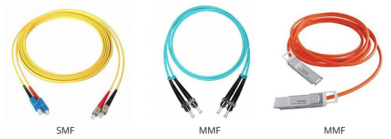
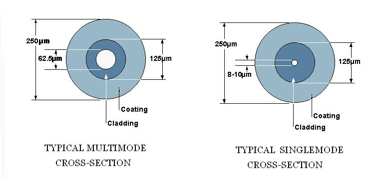
40G network are now being extensively adopted within LANs and data centers. 100G is still predominantly in the carrier network, but could soon extend its stretch to your local network. There exists much confusion as to whether to choose single-mode fiber (SMF) or multimode fiber (MMF) for deploying 40G bandwidth, considering the single mode vs multimode fiber cost. As well as how to get fully prepared for scaling to higher-speed 100G. If you are hesitating to make the choice, you may find this article helpful.

40G Cost: Difference Between SMF and MMF

Multimode Fiber (MMF): Cost-effective With Higher Tolerance to Dirt

Cost-effectiveness: Multimode fiber (MMF) has been evolving to handle the escalating speed: OM3 has been superseded by OM4 and OM5 is there ready to use. MMF has a wider array of short distance transceivers that are easier to get. One of the liable argument that in favor of using MMF is that multimode optics use less power than single-mode ones, but only in condition that you have tens of thousands of racks. In essence, MMF still has its position under certain circumstances, like cabling within the same rack, in Fiber Channel and for backbone cabling in some new construction buildings.

smf mmf

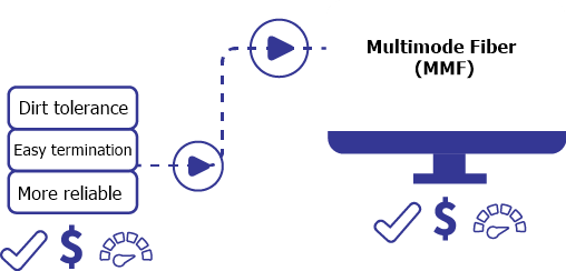
Tolerance to Dirt: Multimode fiber tends to have a lot more tolerance to dirty connections than single-mode fiber. It can handle very dirty couples or connectors to ensure reliable and consistent link performance. Besides, it is easy to terminate, and more accommodating bend radius. So MMF is preferred by links that change frequently or are less than permanent.

smf mmf

Single-mode Fiber (SMF): Higher Capability and Better Future-proofing

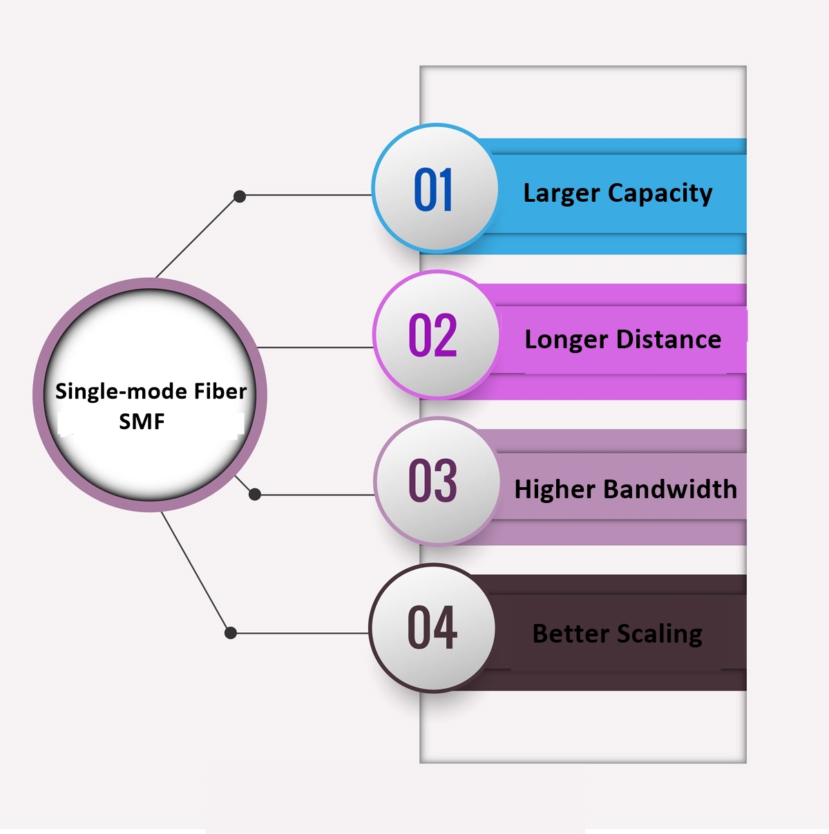
Speed capability: Capacities are really vital for network growth. SMF does so with relatively larger capability than that of MMF. The gap between SMF and MMF cabling is much wider for high-density, high-speed networks. If you want to go further with SMF, say scaling to 100G or beyond, you simply need to upgrade the optics. Unlike using MMF, in which you have to upgrade the glass (OM3 to OM4 to OM5), the labor cost concerning this cannot be underestimated. The capacity for scaling of SMF alone makes it worth the cost. You can use single-mode for almost everything, no need for media conversion. SMF offers enough bandwidth to last a long time, making it possible to upgrade 100 Gbps to Tbps with CWDM/DWDM.

smf mmf

Future proofing: Despite the fact that SM optical transceivers usually cost higher than MM optics, SMF cabling is cheaper and can support much longer distance and reliable performance. Not to mention that bandwidth on SMF keeps going up and up on the same old glass. The good news is that the cost of SMF is dropping in recent years, and it is redesigning to run with less power, thus advocators of SMF think that it is pretty much the only rational choice for infrastructure cabling and the sure winner for today and tomorrow.

SMF and MMF: A Simple Comparison of Cost

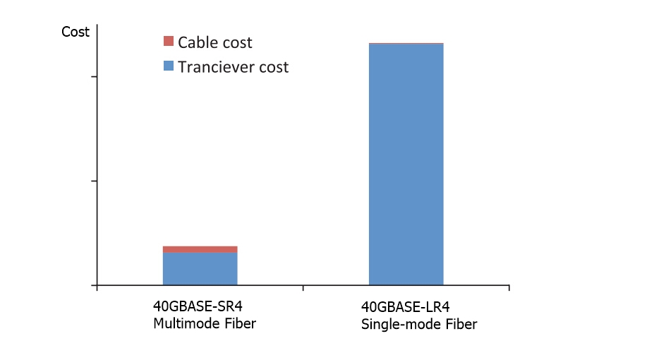
There is no doubt that SMF is a better investment in the long run, but MMF still has a long way to go in data center interconnections. In fact the price difference of SMF optics and MMF optics can be minimized if you choose the right solution. Assuming to connect two 40G devices at 70 m away, let’s see the single mode vs multimode fiber cost for deployment in the following chart.

Module Connector Type SMF or MMF Price 2 Connections 4 Connections 6 Connections
40GBASE-SR4 MPO12 MMF, OM4 $49.00 $564.48 $1128.96 $1693.44
40GBASE-BiDi LC MMF, OM4 $300.00 $1534.24 $2734.24 $3934.24
40GBASE-LR4 LC SMF, OS2 $340.00 $1,609.84 $2,969.84 $4,329.84
80 Gbit 160 Gbit 240 Gbit


Conclusion

Choosing the right fiber for your network application is a critical decision. Understanding your system requirements in order to select the appropriate fiber will maximize the value and performance of your cabling system. Be sure to select the right cable on the basis of aspects including link length, performance, and of course costs. FS provides a broad range of 40G optical transceivers and fiber patch cables with superior quality and fair price. For more details, please visit www.fs.com.

Related Article: Single Mode vs Multimode Fiber: What’s the Difference? 


Common Mistakes in Fiber Optic Network Installation

Share

When install a fiber optic network, people may make some common mistakes, which were usually overlooked. In this article, I will list the most common ones. Hope to give you some guidance for your optical network installation.

1. Single Strand Fiber Device Must Be Used in Pairs

You will never buy two left shoes, but people often make a similar mistake when they’re working with Single Strand Fiber (SSF). Single strand fiber technology allows for the use of two independent wavelengths, such as 1310 and 1550 nm, on the same piece of cable. The most common single strand fiber device is Bi-Directional (BiDi) transceiver. Two BiDi transceiver must be matched correctly. One unit must be a 1310nm-TX/1550nm-RX transceiver (transmitting at 1310 nm, receiving at 1550 nm) and the other must be a 1550nm-TX/1310nm-RX transceiver (transmitting at 1550 nm, receiving at 1310 nm). The 1550nm-TX/1310nm-RX transceiver is more expensive than the 1310nm-TX/1550nm-RX transceiver, due to the cost of their more powerful lasers. So network engineers may hope to save money by installing a pair of 1310nm-TX/1550nm-RX transceivers. But, like mismatched shoes, it doesn’t work.

single-strand-fiber

2. Don’t Use Single-Mode Fiber over Multimode Fiber

Some people may want to make use of legacy cabling or equipment from an older fiber installation to save cost. But keep in mind that single-mode and multimode fiber are usually incompatible. Multimode fiber uses cable with a relatively large core size, typically 62.5 microns (om2, om3 and om4), and 50 microns (om1) still used in some installations. The larger core size simplifies connections and allows for the use of less powerful, less expensive light sources.  But the light therefore tends to bounce around inside the core, which increases the modal dispersion. That limits multimode’s useful range to about 2 km. Single-mode fiber combines powerful lasers and cabling with a narrow core size of 9/125 microns to keep the light focused.  It has a range of up to 120 km, but it is also more expensive. If you tried to use single-mode fiber over a multimode fiber run.  The core size of the fiber cable would be far too large.  You’d get dropped packets and CRC errors.

single-mode-multimode-fiber

3. Understand All kinds of Fiber connectors First

Fiber optic transceivers use a variety of connectors, so make clear their differences before you begin ordering products for a fiber installation is necessary. SC (stick and click) is a square connector. ST (stick and twist) is a round, bayonet-type. LC, or the “Lucent Connector”, was developed by Lucent Technologies to address complaints that ST and SC were too bulky and too easy to dislodge. LC connectors look like a compact version of the SC connector. SFP (small form‐factor pluggable) transceivers usually use LC connector.  Less common connectors include MT-RJ and E2000.

st-lc-sc

4.Connector Links and Splice Times Also Affect 

Although single-mode fiber suffers from less signal loss per km than multimode, all fiber performance is affected by connectors and splices. The signal loss at a single connector or splice may seem insignificant. But as connectors and splices become more numerous signal loss will steadily increase. Typical loss factors would include 0.75 dB per connector, 1 dB per splice, 0.4 dB attenuation per km for single-mode fiber and 3.5 dB attenuation per km for multimode fiber.  Add a 3 dB margin for safety. The more splices and connectors you have in a segment, the greater the loss on the line.

5. Don’t Use APC connector with UPC Connector

Fiber connections may use Angle Polished Connectors (APC) or Ultra Polished Connectors (UPC), and they are not interchangeable. There are physical differences in the ferules at the end of the terminated fiber within the cable (shown in the figure below).  An APC ferrule end-face is polished at an 8° angle, while the UPC is polished at a 0° angle. If the angles are different, some of the light will fail to propagate, becoming connector or splice loss. UPC connectors are common in Ethernet network equipment like media converters, serial devices and fiber‐based switches. APC connectors are typical for FTTX and PON connections.  ISPs are increasingly using APC.

apc-upc-connector

6. Don’t Connect SFP to SFP+ Transceivers

Small Form Pluggable (SFP) transceivers are more expensive than fixed transceivers.  But they are hot swappable and their small form factor gives them additional flexibility. They’ll work with cages designed for any fiber type and their prices are steadily dropping.  So they have become very popular. Standard SFPs typically support speeds of 100 Mbps or 1 Gbps. XFP and SFP+ support 10 Gbps connections. SFP+ is smaller than XFP and allows for greater port density.  Though the size of SFP and SFP+ is the same, you can’t connect SFP+ to a device (SFP) that only supports 1 Gbps.

Related Article: Optical Module Maintenance Methods and Installation Tips

What Kind of Single Mode Fiber Should You Choose?

Share

As we all know, multimode fiber is usually divided into OM1, OM2, OM3 and OM4. Then how about single mode fiber? In fact, the types of single mode fiber seem much more complex than multimode fiber. There are two primary sources of specification of single mode optical fiber. One is the ITU-T G.65x series, and the other is IEC 60793-2-50 (published as BS EN 60793-2-50). Rather than refer to both ITU-T and IEC terminology, I’ll only stick to the simpler ITU-T G.65x in this article. There are 19 different single mode optical fiber specifications defined by the ITU-T.

Name Type
ITU-T G.652 ITU-T G.652.A, ITU-T G.652.B, ITU-T G.652.C, ITU-T G.652.D
ITU-T G.653 ITU-T G.653.A, ITU-T G.653.B
ITU-T G.654 ITU-T G.654.A, ITU-T G.654.B, ITU-T G.654.C
ITU-T G.655 ITU-T G.655.A, ITU-T G.655.B, ITU-T G.655.C, ITU-T G.655.D, ITU-T G.655.E
ITU-T G.656 ITU-T G.656
ITU-T G.657 ITU-T G.657.A, ITU-T G.657.B, ITU-T G.657.C, ITU-T G.657.D

Each type has its own area of application and the evolution of these optical fiber specifications reflects the evolution of transmission system technology from the earliest installation of single mode optical fiber through to the present day. Choosing the right one for your project can be vital in terms of performance, cost, reliability and safety. In this post, I may explain a bit more about the differences between the specifications of the G.65x series of single mode optical fiber families. Hope to help you make the right decision.

G.652
The ITU-T G.652 fiber is also known as standard SMF (single mode fiber) and is the most commonly deployed fiber. It comes in four variants (A, B, C, D). A and B have a water peak. C and D eliminate the water peak for full spectrum operation. The G.652.A and G.652.B fibers are designed to have a zero-dispersion wavelength near 1310 nm, therefore they are optimized for operation in the 1310-nm band. They can also operate in the 1550-nm band, but it is not optimized for this region due to the high dispersion. These optical fibers are usually used within LAN, MAN and access network systems. The more recent variants (G.652.C and G.652.D) feature a reduced water peak that allows them to be used in the wavelength region between 1310 nm and 1550 nm supporting Coarse Wavelength Division Multiplexed (CWDM) transmission.

G.652 

G.653
G.653 single mode fiber was developed to address this conflict between best bandwidth at one wavelength and lowest loss at another. It uses a more complex structure in the core region and a very small core area, and the wavelength of zero chromatic dispersion was shifted up to 1550 nm to coincide with the lowest losses in the fiber. Therefore, G.653 fiber is also called dispersion-shifted fiber (DSF). G.653 has a reduced core size, which is optimized for long-haul single mode transmission systems using erbium-doped fiber amplifiers (EDFA). However, its high power concentration in the fiber core may generate nonlinear effects. One of the most troublesome, four-wave mixing (FWM), occurs in a Dense Wavelength Division Multiplexed (CWDM) system with zero chromatic dispersion, causing unacceptable crosstalk and interference between channels.

G.653

G.654
The G.654 specifications entitled “characteristics of a cut-off shifted single mode optical fiber and cable.” It uses a larger core size made from pure silica to achieve the same long-haul performance with low attenuation in the 1550-nm band. It usually also has high chromatic dispersion at 1550 nm, but is not designed to operate at 1310 nm at all. G.654 fiber can handle higher power levels between 1500 nm and 1600 nm, which is mainly designed for extended long-haul undersea applications.

G.655
G.655 is known as non-zero dispersion-shifted fiber (NZDSF). It has a small, controlled amount of chromatic dispersion in the C-band (1530-1560 nm), where amplifiers work best, and has a larger core area than G.653 fiber. NZDSF fiber overcomes problems associated with four-wave mixing and other nonlinear effects by moving the zero-dispersion wavelength outside the 1550-nm operating window. There are two types of NZDSF, known as (-D)NZDSF and (+D)NZDSF. They have respectively a negative and positive slope versus wavelength. The following picture depicts the dispersion properties of the four main single mode fiber types. The typical chromatic dispersion of a G.652 compliant fiber is 17ps/nm/km. G.655 fibers were mainly used to support long-haul systems that use DWDM transmission.

G.655

G.656
As well as fibers that work well across a range of wavelengths, some are designed to work best at specific wavelengths. This is the G.656, which is also called Medium Dispersion Fiber (MDF). It is designed for local access and long haul fiber that performs well at 1460 nm and 1625 nm. This kind of fiber was developed to support long-haul systems that use CWDM and DWDM transmission over the specified wavelength range. And at the same time, it allows the easier deployment of CWDM in metropolitan areas, and increase the capacity of fiber in DWDM systems.

G.657
G.657 single mode fiber
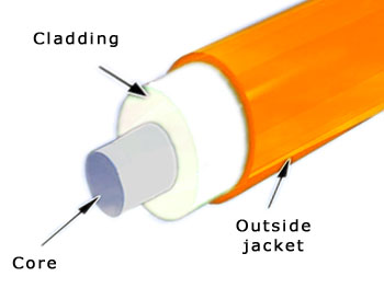
G.657 optical fibers are intended to be compatible with the G.652 optical fibers but have differing bend sensitivity performance. It is designed to allow fibers to bend, without affecting performance. This is achieved through an optical trench that reflects stray light back into the core, rather than it being lost in the cladding, enabling greater bending of the fiber. As we all know, in cable TV and FTTH industries, it is hard to control bend radius in the field. G.657 is the latest standard for FTTH applications, and, along with G.652 is the most commonly used in last drop fiber networks.

From the passage above, we know that different kind of single mode fiber has different application. Since G.657 is compatible with the G.652, some planners and installers are usually likely to come across them. In fact, G657 has a larger bend radius than G.652, which is especially suitable for FTTH applications. And due to problems of G.643 being used in WDM system, it is now rarely deployed, being superseded by G.655. G.654 is mainly used in subsea application. According to this passage, I hope you have a clear understanding of these single mode fibers, which may help you make the right decision.

Related Article: https://community.fs.com/blog/what-kind-of-single-mode-fiber-should-you-choose.html

SMF or MMF? Which Is the Right Choice for Data Center Cabling?

Share

Selecting the right cabling plant for data center connectivity is critically important. The wrong decision could leave a data center incapable of supporting future growth, requiring an extremely costly cable plant upgrade to move to higher speeds. In the past, due to high cost of single-mode fiber (SMF), multimode fiber (MMF) has been widely and successfully deployed in data center for many years. However, as technologies have evolved, the difference in price between SMF and MMF transceivers has been largely negated. With cost no longer the dominant decision criterion, operators can make architectural decisions based on performance. Under these circumstances, should we choose SMF or MMF? This article may give you some advice.

MMF Can’t Reach the High Bandwidth-Distance Needs
MMF datacenter
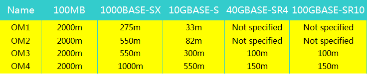
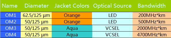
Based on fiber construction multimode fiber has different classifications types that are used to determine what optical signal rates are supported over what distances. Many data center operators who deployed MMF OM1/OM2 fiber a few years ago are now realizing that the older MMF does not support higher transmit rates like 40GbE and 100GbE. As a result, some MMF users have been forced to add later-generation OM3 and OM4 fiber to support standards-based 40GbE and 100GbE interfaces. However, multimode fiber’s physical limitations mean that as data traffic grows and interconnectivity speeds increase, the distance between connections must decrease. The only alternative in an multimode fiber world is to deploy more fibers in parallel to support more traffic. Therefore, while MMF cabling has been widely and successfully deployed for generations, its limitations now become even more serious. Operators must weigh unexpected cabling costs against a network incapable of supporting new services.

SMF Maybe a Viable Alternative
Previously, organizations were reluctant to implement SMF inside the data center due to the cost of the pluggable optics required, especially compared to MMF. However, newer silicon technologies and manufacturing innovations are driving down the cost of SMF pluggable optics. Transceivers with Fabry-Perot edge emitting lasers (single-mode) are now comparable in price and power dissipation to VCSEL (multimode) transceivers. Besides, Where MMF cable plants introduce a capacity-reach tradeoff, SMF eliminates network bandwidth constraints. This allows operators to take advantage of higher-bit-rate interfaces and wave division multiplexing (WDM) technology to increase by three orders of magnitude the amount of traffic that the fiber plant can support over longer distances. All these factors make SMF a more viable option for high-speed deployments in data centers.

SMF datacenter

Comparison Between SMF and MMF
10GbE has become the predominant interconnectivity interface in large data centers, with 40GbE and 100GbE playing roles in some high-bandwidth applications. Put simply, the necessity for fiber cabling that supports higher bit rates over extended distances is here today. With that in mind, the most significant difference between SMF and MMF is that SMF provides a higher spectral efficiency, which means it supports more traffic over a single fiber using more channels at higher speeds. This is in stark contrast to multimode fiber, where cabling support for higher bit rates is limited by its large core size. This effectively limits the distance higher speed signals can travel over MMF fiber. In fact, in most cases, currently deployed MMF cabling is unable to support higher speeds over the same distance as lower-speed signals.

Name Interface FP (SMF) VCSEL (MMF)
Link Budget (dB)
4 to 6 2
Reach (in meters) (Higher value is better)
10GbE 1300 300
40GbE 1300 150
100GbE 1300 <100

Conclusion
As operators consider their cabling options, the tradeoff between capacity and reach is important. Network operators must assess the extent to which they believe their data centers are going to grow. For environments where users, applications, and corresponding workload are all increasing, single mode fiber offers the best future proofing for performance and scalability than multimode fiber. And because of fundamental changes in how transceivers are manufactured, those benefits can be attained at prices comparable to SMF’s lower performing alternative.

Source: Single Mode vs Multimode Fiber: What’s the Difference?

WBMMF – Next Generation Duplex Multimode Fiber in the Data Center

Share

Enterprise data center and cloud operators use multimode fiber for most of their deployments because it offers the lowest cost means of transporting high data rates for distances aligned with the needs of these environments. The connections typically run at 10G over a duplex multimode fiber pair—one transmit (Tx) fiber and one receive (Rx) fiber. Upgrading to 40G and 100G using MMF has traditionally required the use of parallel ribbons of fiber. While parallel transmission is simple and effective, continuation of this trend drives higher cost into the cabling system. However, a new generation of multimode fiber called WBMMF (wideband multimode fiber) is on the way, which can enable transmission of 40G or 100G over a single pair of fibers rather than the four or ten pairs used today. Now, let’s get close to WBMMF.

What Is Wideband Multimode Fiber?
WBMMF is a new multimode fiber type under development that will extend the ability of conventional OM4 fiber to support multiple wavelengths. Unlike traditional multimode fiber, which supports transmission at the single wavelength of 850 nm, WBMMF will support traffic over a range of wavelengths from 850 to 950 nm. This capability will enable multiple lanes of traffic over the same strand of fiber to transmit 40G and 100G over a single pair of fibers and to drastically increase the capacity of parallel-fiber infrastructure, opening the door to 4-pair 400GE and terabit applications. Multimode fiber continues to provide the most cost-effective platform for high bandwidth connectivity in the data center, and with the launch of the WBMMF solution, that platform has been extended to support higher speeds with fewer fibers and at greater distances.

Wideband Multimode Fiber

What Is the Technology Behind WBMMF?
WBMMF uses short wavelength division multiplexing (SWDM) to significantly increase its transmission capacity by four times. WDM technology is well known for its use in single-mode transmission, but has only recently been adapted for use with vertical cavity surface-emitting lasers (VCSELs), which have been proven in high-speed optical communications and are widely deployed in 10G interconnection applications. SWDM multiplexes different wavelengths onto duplex MMF utilizing WDM VCSEL technology. By simultaneously transmitting four VCSELs, each operating at a slightly different wavelength, a single pair WBMMF can reliably transfer 40G (4x10G) or 100G (4x25G). The use of SWDM then enables WBMMF to maintain the cost advantage of multimode fiber systems over single mode fiber in short links and greatly increases the total link capacity in a multimode fiber link.

SWDM WBMMF

Why Does WBMMF Make Sense?
In order to increase transmission speeds up to 10G or 25G, transceiver vendors simply increased the speed of their devices. When 40G and 100G standards were developed, transmission schemes that used parallel fibers were introduced. This increase in fiber count provided a simple solution to limitations of the technology available at the time. It was accepted in the industry and allowed multimode links to maintain a low cost advantage. However, the fiber count increase was not without issues. At some point, simply increasing the number of fibers for each new speed became unreasonable, in part because the cable management of parallel fiber solutions, combined with the increasing number of links in a data center, becomes very challenging. Please see the picture below. Usually, 40G is implemented using eight of the twelve fibers in an MPO connector. Four of these eight fibers are used to transmit while the other four are used to receive. Each Tx/Rx pair is operating at 10G. But if we use WDMMF, two fibers are enough. Each Tx/Rx pair can transmit 40G by simultaneously transmitting four different wavelengths. This enables at least a four-fold reduction in the number of fibers for a given data rate, which provides a cost-effective cabling solution for data center.

Parallel fibers vs WBMMF

Conclusion
WBMMF is born at the right moment to meet the challenges associated with escalating data rates and the ongoing need to build cost-effective infrastructure. Besides, WBMMF will support existing OM4 applications to the same link distance. Optimized to support wavelengths in the 850 nm to 950 nm range to take advantage of SWDM, WBMMF ensures not only more efficient support for future applications to useful distances, but also complete compatibility with legacy applications, making it an ideal universal medium that supports not only the applications of the present, but also those of the future.

Related Article: OM5 Multimode Fiber FAQs

Understanding Fiber Optic Wavelength

Share

The light we are most familiar with is surely the light we can see. Our eyes are sensitive to light whose wavelength is in the range of about 400 nm to 700 nm, from the violet to the red. But for fiber optics with glass fibers, we use light in the infrared region which has wavelengths longer than visible light. Because the attenuation of the fiber is less at longer wavelengths. This text may mainly tell you the common types of fiber optic wavelength used in fiber optics and why they are used.

wavelength-nm

Fiber Optic Wavelength Definition

In fact, light is defined by its wavelength. It is a member of the frequency spectrum, and each frequency (sometimes also called color) of light has a wavelength associated with it. Wavelength and frequency are related. Generally, the radiation of shorter wavelengths are identified by their wavelengths, while the longer wavelengths are identified by their frequency.

Common Fiber Optic Wavelengths

Wavelengths typically range from 800 nm to 1600 nm, but by far the most common wavelengths actually used in fiber optics are 850 nm, 1300 nm, and 1550 nm. Multimode fiber is designed to operate at 850 nm and 1300 nm, while single-mode fiber is optimized for 1310 nm and 1550 nm. The difference between 1300 nm and 1310 nm is simply a matter of convention. Both lasers and LEDs are used to transmit light through optical fiber. Lasers are usually used for 1310nm or 1550nm single-mode applications. LEDs are used for 850nm or 1300nm multimode applications.

fiber optic wavelength

Why Those Common Fiber Optic Wavelengths?

As mentioned above, the most common fiber optic wavelength includes 850 nm, 1300 nm and 1550 nm. But why do we use these three wavelengths? Because the attenuation of the fiber is much less at those wavelengths. Therefore, they best match the transmission properties of available light sources with the transmission qualities of optical fiber. The attenuation of glass optical fiber is caused by two factors: absorption and scattering. Absorption occurs in several specific wavelengths called water bands due to the absorption by minute amounts of water vapor in the glass. Scattering is caused by light bouncing off atoms or molecules in the glass.

It is strongly a function of wavelength, with longer wavelengths having much lower scattering. From the chart below, we can obviously see that there are three low-lying areas of absorption, and an ever-decreasing amount of scattering as wavelengths increase. As you can see, all three popular wavelengths have almost zero absorption.

wavelength-nm

Conclusion

After reading this passage, you may know some basic knowledge of wavelengths in fiber optics. Since the attenuation of the wavelengths at 850 nm, 1300 nm, and 1550 nm are relatively less, they are the most three common wavelengths used in fiber optic communication. Fiberstore offer all kinds multimode and single-mode fiber optic transceivers which operate on 850 nm and 1310 nm respectively very well. For more information, please visit fs.com.

Related Article: From O to L: the Evolution of Optical Wavelength Bands

Related Article: The Bandwidth and Window of Fiber Optic Cable

Do You Know About Mode Conditioning Patch Cord?

Share

The great demand for increased bandwidth has prompted the release of the 802.3z standard (IEEE) for Gigabit Ethernet over optical fiber. As we all know, 1000BASE-LX transceiver modules can only operate on single-mode fibers. However, this may pose a problem if an existing fiber network utilizes multimode fibers. When a single-mode fiber is launched into a multimode fiber, a phenomenon known as Differential Mode Delay (DMD) will appear. This effect can cause multiple signals to be generated which may confuse the receiver and produce errors. To solve this problem, a mode conditioning patch cord is needed. In this article, some knowledge of mode conditioning patch cords will be introduced.

What Is a Mode Conditioning Patch Cord?

A mode conditioning patch cord is a duplex multimode cord that has a small length of single-mode fiber at the start of the transmission length. The basic principle behind the cord is that you launch your laser into the small section of single-mode fiber, then the other end of the single-mode fiber is coupled to multimode section of the cable with the core offset from the center of the multimode fiber (see diagram below).

mode conditioning patch cord

This offset point creates a launch that is similar to typical multimode LED launches. By using an offset between the single-mode fiber and the multimode fiber, mode conditioning patch cords eliminate DMD and the resulting multiple signals allowing use of 1000BASE-LX over existing multimode fiber cable systems. Therefore, these mode conditioning patch cords allow customers an upgrade of their hardware technology without the costly upgrade of their fiber plant.

Some Tips When Using Mode Conditioning Patch Cord

After learning about some knowledge of mode conditioning patch cords, but do you know how to use it? Then some tips when using mode conditioning cables will be presented.

    • Mode conditioning patch cords are usually used in pairs. Which means that you will need a mode conditioning patch cord at each end to connect the equipment to the cable plant. So these patch cords are usually ordered in numbers. You may see someone only order one patch cord, then it is usually because they keep it as a spare.
    • If your 1000BASE-LX transceiver module is equipped with SC or LC connectors, please be sure to connect the yellow leg (single-mode) of the cable to the transmit side, and the orange leg (multimode) to the receive side of the equipment. The swap of transmit and receive can only be done at the cable plant side. See diagram below.

mode conditioning patch cord

  • Mode conditioning patch cords can only convert single-mode to multimode. If you want to convert multimode to single-mode, then a media converter will be required.
  • Besides, mode conditioning patch cables are used in the 1300nm or 1310nm optical wavelength window, and should not be used for 850nm short wavelength window such as 1000Base-SX.

Conclusion

From the text, we know that mode conditioning patch cords really significantly improve the data signal quality and increase the transmission distance. But when using it, there are also some tips must be kept in mind. Fiberstore offer mode conditioning patch cords in all varieties and combinations of SC, ST, MT-RJ and LC fiber optic connectors. All of the Fiberstore’s mode conditioning patch cords are at high quality and low price. For more information, please visit fs.com.

What are OM1, OM2, OM3 and OM4?

Share

There are different types of fiber optic cable. Some types are single-mode, and some types are multimode. Multimode fibers are described by their core and cladding diameters. Usually the diameter of the multimode fiber is either 50/125 µm or 62.5/125 µm. At present, there are four kinds of multi-mode fibers: OM1, OM2, OM3 and OM4. The letters “OM” stand for optical multimode. Each type of them has different characteristics.

Standard

Each “OM” has a minimum Modal Bandwidth (MBW) requirement. OM1, OM2, and OM3 fiber are determined by the ISO 11801 standard, which is based on the modal bandwidth of the multimode fiber. In August of 2009, TIA/EIA approved and released 492AAAD, which defines the performance criteria for OM4. While they developed the original “OM” designations, IEC has not yet released an approved equivalent standard that will eventually be documented as fiber type A1a.3 in IEC 60793-2-10.

Specifications

  • OM1 cable typically comes with an orange jacket and has a core size of 62.5 micrometers (µm). It can support 10 Gigabit Ethernet at lengths up 33 meters. It is most commonly used for 100 Megabit Ethernet applications.
  • OM2 also has a suggested jacket color of orange. Its core size is 50µm instead of 62.5µm. It supports 10 Gigabit Ethernet at lengths up to 82 meters but is more commonly used for 1 Gigabit Ethernet applications.
  • OM3 fiber has a suggested jacket color of aqua. Like OM2, its core size is 50µm. It supports 10 Gigabit Ethernet at lengths up to 300 meters. Besides OM3 is able to support 40 Gigabit and 100 Gigabit Ethernet up to 100 meters. 10 Gigabit Ethernet is its most common use.
  • OM4 also has a suggested jacket color of aqua. It is a further improvement to OM3. It also uses a 50µm core but it supports 10 Gigabit Ethernet at lengths up 550 meters and it supports 100 Gigabit Ethernet at lengths up to 150 meters.

OM1, OM2, OM3 and OM4 multi-mode fiber

Differences

There are several differences between four kinds of multi-mode fiber, and we can see them clearly from the table below:
OM1, OM2, OM3 and OM4 multi-mode fiber

  • Diameter: The core diameter of OM1 is 62.5 µm , however, core diameter of the OM2, OM3 and OM4 is 50 µm.
  • Jacket Color: OM1 and OM2 MMF are generally defined by an orange jacket. OM3 and OM4 are usually defined with an aqua jacket.
  • Optical Source: OM1 and OM2 commonly use LED light source. However, OM3 and OM4 usually use 850 nm VCSELs.
  • Bandwidth: At 850 nm the minimal modal bandwidth of OM1 is 200MHz*km, of OM2 is 500MHz*km, of OM3 is 2000MHz*km, of OM4 is 4700MHz*km.

OM3 & OM4 are Superior to OM1&OM2

10G OM3Both OM1 and OM2 work with LED based equipment that can send hundreds of modes of light down the cable, while OM3 and OM4 are optimized for laser (eg. VCSEL) based equipment that uses fewer modes of light. LEDs can not be turned on/off fast enough to support higher bandwidth applications, while VCSELs are capable of modulation over 10 Gbit/s and are used in many high speed networks. For this reason, OM3 and OM4 are the only multi-mode fibers included in the 40G and 100G Ethernet standard. Now OM1 and OM2 are usually used for 1G which are not suitable for today’s higher-speed networks. OM3 and OM4 are used for 10G mostly at present. But in the future, since OM3 and OM4 can support the 40G and 100G, which may make them the tendency.

Related article: Singl-mode vs. Multimode Fiber Cable

What’s the Difference: Single Mode vs Multimode Fiber

Share

fiber cable diagAn optical fiber is a flexible, transparent fiber made of extruded glass or plastic, slightly thicker than a human hair. Optical fibers are used most often as a means to transmit light between the two ends of the fiber and find wide usage in fiber-optic communications, where they permit transmission over longer distances and at higher bandwidths than wire cables. Optical fibers typically include a transparent core surrounded by a transparent cladding material with a lower index of refraction. Light is kept in the core by the phenomenon of total internal reflection which causes the fiber to act as a waveguide. In general, there are two kinds of optical fiber: fibers that support many propagation paths or transverse modes are called multimode fibers (MMF), while those that support a single mode are called single mode fibers (SMF). Single mode vs multimode fiber: what’s difference between them? Reading this text will help you get the answer.

Single Mode vs Multimode Fiber: What’s single mode optical fiber?

In fiber-optic communication, a single mode optical fiber (SMF) is an optical fiber designed to carry light only directly down the fibre – the transverse mode. For single mode optical fiber, no matter it operates at 100 Mbit/s or 1 Gbit/s date rates , the transmission distance can reach to at least 5 km. Typically, it is used for long-distance signal transmission.

single mode fiber

Single Mode vs Multimode Fiber: What’s multimode optical fiber?

Multimode optical fiber (MMF) is a type of optical fiber mostly used for communication over short distances, such as within a building or on a campus. Typical transmission speed and distance limits are 100 Mbit/s for distances up to 2 km (100BASE-FX), 1 Gbit/s up to 1000m, and 10 Gbit/s up to 550 m. There are two kinds of multimode indexes: step index and graded index.

multimode fiber

What’s difference between single mode optical fiber and multimode?

  • Core diameter

The main difference between multimode and single mode fiber is that the former has much larger core diameter, typically has a core diameter of 50 or 62.5 µm and a cladding diameter of 125 µm. While a typical single mode fiber has a core diameter between 8 and 10 µm and a cladding diameter of 125 µm.

Single Mode vs Multimode Fiber

  • Optical source
    Both lasers and LEDs are used as light sources. Laser light sources are significantly more expensive than LED light sources however they produce a light that can be precisely controlled and which has a high power. Because the LED light sources produce a more dispersed light source (many modes of light) these light sources are used with multimode
    cable. While a laser source is used (which produces close to a single mode of light) with single mode cable.

Single Mode vs Multimode Fiber

  • Bandwidth
    Since multimode fiber has a larger core-size than single mode fiber, it supports more than one propagation mode. Besides, like multimode fibers, single-mode fibers do exhibit modal dispersion resulting from multiple spatial modes, but the modal dispersion of single mode fiber is less than multi-mode fiber. For these reasons, single mode fibers can have a higher bandwidth than multi-mode fibers.
  • Jacket color
    Jacket color is sometimes used to distinguish multimode cables from single mode ones. The standard TIA-598C recommends, for non-military applications, the use of a yellow jacket for single mode fiber, and orange or aqua for multimode fiber, depending on type. Some vendors use violet to distinguish higher performance OM4 communications fiber from other types.

Single Mode vs Multimode Fiber

  • Modal dispersion
    The LED light sources sometimes used with multimode fiber produce a range of wavelengths and these each propagate at different speeds. This will lead to much modal dispersion, which is a limit to the useful length for multimode fiber optic cable. In contrast, the lasers used to drive single mode fibers produce coherent light of a single wavelength. Hence its modal dispersion is much less than multimode fiber. Due to the modal dispersion, multimode fiber has higher pulse spreading rates than single mode fiber, limiting multimode fiber’s information transmission capacity.

Single Mode vs Multimode Fiber

  • Price
    For multimode fiber can support multiple light mode, the price of it is higher than single-mode fiber. But in terms of the equipment, because single mode fiber normally uses solid-state laser diodes, therefore, the equipment for single mode fiber is more expensive than equipment for multimode fiber. And for this reason , the cost of using multimode fiber is much less than using single-mode fiber instead.

Single Mode vs Multimode Fiber: What kind of optical fiber should I choose?

This is based on transmission distance to be covered as well as the overall budget allowed. If the distance is less than a couple of miles, multimode fiber will work well and transmission system costs (transmitter and receiver) will be in the $500 to $800 range. If the distance to be covered is more than 3-5 miles, single mode fiber is the choice. Transmission systems designed for use with this fiber will typically cost more than $1000 due to the increased cost of the laser diode. Single mode vs multimode fiber: Do you know the differences now?

Related Article: Single Mode Fiber: How Much Do You Know?

Comparison Between OS1 and OS2 SMF Cables

Low-loss Connectivity For Multimode Fiber Applications

Share

Optical insertion loss budgets are now one of the top concerns among data center managers, especially in today’s large virtualized server environments with longer-distance 40 and 100 gigabit Ethernet (GbE) backbone switch-to-switch deployments for networking and storage area networks (SANs). In fact, loss budgets need to be carefully considered during the early design stages of any data center—staying within the loss budget is essential for ensuring that optical data signals can properly transmit from one switch to another without high bit error rates and performance degradation.

low-loss-multifiber-connectivity

With the length and type of the fiber optic cable and number of connectors and splices all contributing to the link loss, data center managers are faced with the challenge of calculating each connection point and segment within their fiber channels. Multi-fiber push on (MPO) or mechanical transfer push on (MTP) connectors are rapidly becoming the norm for switch-to-switch connections due to their preterminated plug and play benefits and ease of scalability from 10 to 40 and 100 gigabit speeds. Unfortunately, typical MPO MTP module insertion loss may not allow for having more than two mated connections in a fiber channel, which significantly limits design flexibility and data center management. Low loss, rather than standard loss, MPO/MTP connectors better support multiple mated connections for flexibility over a wide range of distances and configurations while remaining within the loss budget.

MTP LC

Typical MPO/MTP connectors, which are required for 40 and 100 GbE eployments have insertion loss values that range from 0.3 dB to 0.5 dB. Typical LC multimode fiber connectors have loss values that range from 0.3 dB to 0.5 dB. While better than the allowed 0.75 dB TIA value, typical connector loss still limits how many connections can be deployed in 10, 40 and 100 GbE channels. For example, with an LC connector loss of 0.5 dB, a 300-meter 10 GbE channel over OM3 fiber can include only three connectors with no headroom. Having just two or three connections prevents the use of cross connects at both interconnection (MDA) and access switches (HDA).

Due to improvements in connector technology and manufacturing techniques, Fiberstore has succeeded in lowering the loss to 0.20 dB for MTP connectors and to 0.15 dB (0.1 dB typical) for LC and SC connectors, well below the industry standard of 0.75 dB and loss values offered by other manufacturers.

For 10 GbE, Fiberstore low loss LC fiber jumpers offer a loss of 0.15 dB (typical 0.1 dB) and Fiberstore low loss plug and play MTP to LC or SC modules offer a loss of 0.35 dB (typical 0.25 dB). For 40 and 100 GbE, MTP to MTP pass-through adapter plates and MTP fiber jumpers offer a loss of 0.2 dB. These lower loss values allow data center managers to deploy more connection points in fiber channels, enabling the use of distribution points or cross connects that significantly increase flexible configuration options.

Table 2 below provides an example of how many connections can be deployed in 10, 40 and 100 GbE channels over OM3 and OM4 multimode fiber using low loss MTP to LC modules for 10 GbE and low loss MTP to MTP pass-through adapters for 40 and 100 GbE versus standard loss solutions.

As indicated in Table 2, the use of low loss connectivity allows for four connections in a 10 GbE OM3 or OM4 channel compared to just two when using standard loss connectivity. Low loss connectivity allows for eight connections in a 100- meter 40/100 GbE channel over OM3 versus just four connections using standard loss, and five connections in a 150-meter 40/100 GbE channel over OM4 fiber compared to just two connections using standard loss. Deploying cross connects between interconnection and access switches requires a minimum of four connections, depending on the configuration. Therefore, cross connects in a full-distance optical channel are simply not feasible without low loss connectivity.

Figures 6, 7 and 8 shows some example scenarios for deploying cross connects in 10 GbE and 40/100 GbE channels over OM3 and OM4 fiber using Fiberstore low loss fiber connectivity. In Figure 6, all changes are made at the cross connect with LC fiber jumpers. The switches remain separate and the permanent MTP trunk fiber cables need only be installed once. The cross connect can be placed anywhere within the channel to maximize ease of deployment and manageability.

MTP Trunk Cable

Figure 7. shows an OM3 40/100 GbE channel with six Fiberstore low loss MTP-MTP pass-through adapter plates and low loss trunks. This scenario offers 0.4 dB of headroom and provides even better manageability and security. All changes are made at the cross connects via MTP fiber jumpers, switches remain separate, and the MTP trunk cables need only be installed once.Once again, the cross connects can be located anywhere in the data center for maximum flexibility. This allows for one-time deployment of high fiber-count cabling from the cross connect at the interconnection switch to the cross connect at the access switch. Adding additional access switches can be accomplished with short fiber runs from the cross connect.

Figure 7: For maximum flexibility, manageability and security, up to eight low loss MTP-MTP pass-through adapters can be deployed using low loss trunks in a 100-meter 40/100 GbE switch-to-switch backbone channel over OM3 fiber.

If the loss budget does not permit deploying six MTP to MTP adapters, one option is to deploy MTP to LC or MTP to MTP jumpers from the cross connect to the equipment, depending on the equipment interface. For example, if using OM4 fiber to extend the channel distance to 150 meters, up to five Low Loss MTP-MTP pass through adapters can be deployed as shown in Figure 8.