Tag Archives: optical fiber

What Are the Fiber Optic Cable Advantages and Disadvantages?

Share

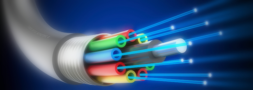
What are the fiber optic cable advantages and disadvantages? An optical fiber or fiber optic cable is a flexible, transparent fiber made by drawing glass, which are used most often as a means to transmit light between the two ends of the fiber and find wide usage in fiber-optic communications, where they permit transmission over longer distances and at higher bandwidths (data rates) than wire cables. Whether should I use optical fiber cables in my network? Single mode fiber or multimode fiber? Don’t worry, read through this post to learn both fiber optic cable advantages and disadvantages and then make a right choice.

optical fiber

Fiber Optic Cable Advantages and Disadvantages

Advantages of Optical Fiber Cable
  • Bandwidth

Fiber optic cables have a much greater bandwidth than metal cables. The amount of information that can be transmitted per unit time of fiber over other transmission media is its most significant advantage.

  • Low Power Loss

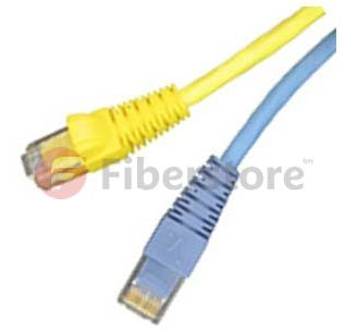
An optical fiber offers low power loss, which allows for longer transmission distances. In comparison to copper, in a network, the longest recommended copper distance is 100m while with fiber, it is 2km.

  • Interference

Fiber optic cables are immune to electromagnetic interference. It can also be run in electrically noisy environments without concern as electrical noise will not affect fiber.

  • Size

In comparison to copper, a fiber optic cable has nearly 4.5 times as much capacity as the wire cable has and a cross sectional area that is 30 times less.

  • Weight

Fiber optic cables are much thinner and lighter than metal wires. They also occupy less space with cables of the same information capacity.  Lighter weight makes fiber easier to install.

  • Security

Optical fibers are difficult to tap. As they do not radiate electromagnetic energy, emissions cannot be intercepted. As physically tapping the fiber takes great skill to do undetected, fiber is the most secure medium available for carrying sensitive data.

  • Flexibility

An optical fiber has greater tensile strength than copper or steel fibers of the same diameter. It is flexible, bends easily and resists most corrosive elements that attack copper cable.

  • Cost

The raw materials for glass are plentiful, unlike copper. This means glass can be made more cheaply than copper.

Disadvantages of Optical Fiber Cable
  • Difficult to Splice

The optical fibers are difficult to splice, and there are loss of the light in the fiber due to scattering. They have limited physical arc of cables. If you bend them too much, they will break.

  • Expensive to Install

The optical fibers are more expensive to install, and they have to be installed by the specialists. They are not as robust as the wires. Special test equipment is often required to the optical fiber.

  • Highly Susceptible

The fiber optic cable is a small and compact cable, and it is highly susceptible to becoming cut or damaged during installation or construction activities. The fiber optic cables can provide tremendous data transmission capabilities. So, when the fiber optic cabling is chosen as the transmission medium, it is necessary to address restoration, backup and survivability.

  • Can’t Be Curved

The transmission on the optical fiber requires repeating at distance intervals. The fibers can be broken or have transmission losses when wrapped around curves of only a few centimeters radius.

Conclusion

Fiber optic cable has both advantages and disadvantages. However, in the long run, optical fiber will replace copper. In today’s network, fiber optic cable becomes more popular than before and is widely used. FS.COM, as a leading optics supplier, provides all kinds of optical fiber cables with high quality and low price for your option.

Related Article: What Are the Most Popular Fiber Optic Cable Types?

Related Article: What Kind of Fiber Patch Cord Should I Choose?

What Kind of Single Mode Fiber Should You Choose?

Share

As we all know, multimode fiber is usually divided into OM1, OM2, OM3 and OM4. Then how about single mode fiber? In fact, the types of single mode fiber seem much more complex than multimode fiber. There are two primary sources of specification of single mode optical fiber. One is the ITU-T G.65x series, and the other is IEC 60793-2-50 (published as BS EN 60793-2-50). Rather than refer to both ITU-T and IEC terminology, I’ll only stick to the simpler ITU-T G.65x in this article. There are 19 different single mode optical fiber specifications defined by the ITU-T.

Name Type
ITU-T G.652 ITU-T G.652.A, ITU-T G.652.B, ITU-T G.652.C, ITU-T G.652.D
ITU-T G.653 ITU-T G.653.A, ITU-T G.653.B
ITU-T G.654 ITU-T G.654.A, ITU-T G.654.B, ITU-T G.654.C
ITU-T G.655 ITU-T G.655.A, ITU-T G.655.B, ITU-T G.655.C, ITU-T G.655.D, ITU-T G.655.E
ITU-T G.656 ITU-T G.656
ITU-T G.657 ITU-T G.657.A, ITU-T G.657.B, ITU-T G.657.C, ITU-T G.657.D

Each type has its own area of application and the evolution of these optical fiber specifications reflects the evolution of transmission system technology from the earliest installation of single mode optical fiber through to the present day. Choosing the right one for your project can be vital in terms of performance, cost, reliability and safety. In this post, I may explain a bit more about the differences between the specifications of the G.65x series of single mode optical fiber families. Hope to help you make the right decision.

G.652
The ITU-T G.652 fiber is also known as standard SMF (single mode fiber) and is the most commonly deployed fiber. It comes in four variants (A, B, C, D). A and B have a water peak. C and D eliminate the water peak for full spectrum operation. The G.652.A and G.652.B fibers are designed to have a zero-dispersion wavelength near 1310 nm, therefore they are optimized for operation in the 1310-nm band. They can also operate in the 1550-nm band, but it is not optimized for this region due to the high dispersion. These optical fibers are usually used within LAN, MAN and access network systems. The more recent variants (G.652.C and G.652.D) feature a reduced water peak that allows them to be used in the wavelength region between 1310 nm and 1550 nm supporting Coarse Wavelength Division Multiplexed (CWDM) transmission.

G.652 

G.653
G.653 single mode fiber was developed to address this conflict between best bandwidth at one wavelength and lowest loss at another. It uses a more complex structure in the core region and a very small core area, and the wavelength of zero chromatic dispersion was shifted up to 1550 nm to coincide with the lowest losses in the fiber. Therefore, G.653 fiber is also called dispersion-shifted fiber (DSF). G.653 has a reduced core size, which is optimized for long-haul single mode transmission systems using erbium-doped fiber amplifiers (EDFA). However, its high power concentration in the fiber core may generate nonlinear effects. One of the most troublesome, four-wave mixing (FWM), occurs in a Dense Wavelength Division Multiplexed (CWDM) system with zero chromatic dispersion, causing unacceptable crosstalk and interference between channels.

G.653

G.654
The G.654 specifications entitled “characteristics of a cut-off shifted single mode optical fiber and cable.” It uses a larger core size made from pure silica to achieve the same long-haul performance with low attenuation in the 1550-nm band. It usually also has high chromatic dispersion at 1550 nm, but is not designed to operate at 1310 nm at all. G.654 fiber can handle higher power levels between 1500 nm and 1600 nm, which is mainly designed for extended long-haul undersea applications.

G.655
G.655 is known as non-zero dispersion-shifted fiber (NZDSF). It has a small, controlled amount of chromatic dispersion in the C-band (1530-1560 nm), where amplifiers work best, and has a larger core area than G.653 fiber. NZDSF fiber overcomes problems associated with four-wave mixing and other nonlinear effects by moving the zero-dispersion wavelength outside the 1550-nm operating window. There are two types of NZDSF, known as (-D)NZDSF and (+D)NZDSF. They have respectively a negative and positive slope versus wavelength. The following picture depicts the dispersion properties of the four main single mode fiber types. The typical chromatic dispersion of a G.652 compliant fiber is 17ps/nm/km. G.655 fibers were mainly used to support long-haul systems that use DWDM transmission.

G.655

G.656
As well as fibers that work well across a range of wavelengths, some are designed to work best at specific wavelengths. This is the G.656, which is also called Medium Dispersion Fiber (MDF). It is designed for local access and long haul fiber that performs well at 1460 nm and 1625 nm. This kind of fiber was developed to support long-haul systems that use CWDM and DWDM transmission over the specified wavelength range. And at the same time, it allows the easier deployment of CWDM in metropolitan areas, and increase the capacity of fiber in DWDM systems.

G.657
G.657 single mode fiberG.657 optical fibers are intended to be compatible with the G.652 optical fibers but have differing bend sensitivity performance. It is designed to allow fibers to bend, without affecting performance. This is achieved through an optical trench that reflects stray light back into the core, rather than it being lost in the cladding, enabling greater bending of the fiber. As we all know, in cable TV and FTTH industries, it is hard to control bend radius in the field. G.657 is the latest standard for FTTH applications, and, along with G.652 is the most commonly used in last drop fiber networks.

From the passage above, we know that different kind of single mode fiber has different application. Since G.657 is compatible with the G.652, some planners and installers are usually likely to come across them. In fact, G657 has a larger bend radius than G.652, which is especially suitable for FTTH applications. And due to problems of G.643 being used in WDM system, it is now rarely deployed, being superseded by G.655. G.654 is mainly used in subsea application. According to this passage, I hope you have a clear understanding of these single mode fibers, which may help you make the right decision.

Related Article: https://community.fs.com/blog/what-kind-of-single-mode-fiber-should-you-choose.html

Optical Fiber Benefits the Green Data Center Building

Share

Green DataCenterWith the amount of energy now required to power the world’s data centers, one of the greatest challenges in today’s data centers is minimizing costs associated with power consumption and cooling, which is also the requirement of building the green data center. Higher power consumption means increased energy costs and greater need for heat dissipation. This requires more cooling, which adds even more cost. Under these circumstances, high-speed optical fiber offers a big advantage over copper to reduce the network operational and cooling energy.

What Is Green Data Center?
The word “green” invokes natural images of deep forests, sprawling oak trees and financial images of dollar bills. The topic of green has been gaining momentum across international, commercial and industrial segments as global warming and greenhouse gas effects hit headlines. In terms of different fields, the word “green” has different definitions. Specific to the data center segment of the telecommunications industry, green data center is a repository for the storage, management, and dissemination of data in which the mechanical, lighting, electrical and computer systems are designed for maximum energy efficiency and minimum environmental impact.

green data enter

How to Build Green Data Center?
Green data center address two issues which plague the average data center. One is the power required to run the actual equipment, the other is the power required to cool the equipment. Reduced the power required will effectively lessen not only the energy consumption but also the impact on environment. Green solutions include:

  • More efficient hardware components and software systems
  • Innovative cooling systems
  • Using natural ways to cool equipment
  • Building near advantageous natural resources or environments
  • Effective server and rack management for better air-flow

How Does Optical Fiber Benefit the Green Data Center Building?
Compared to copper cable, optical fiber may offer many advantages in contribution to building green data center. Usually, optical fiber connectivity can enhance green data center installations by utilizing high-port-density electronics with very low power and cooling requirements. Additionally, an optical network provides premier pathway and space performance in racks, cabinets and trays to support high cooling efficiency when compared to copper connectivity. All these advantages can be summarized as the following three points.

Lower Operational Power Consumption
Optical transceiver requires less power to operate compared to copper transceiver. Copper requires significant analog and digital signal processing for transmission that consumes significantly higher energy when compared to optical media. A 10G BASE-T transceiver in a copper system uses about 6 watts of power. A comparable 10G BASE-SR optical transceiver uses less than 1 watt to transmit the same signal. The result is that each optical connection saves about 5 watts of power. Data centers vary in size, but if we assume 10,000 connections at 5 watts each, that’s 50 kW less power—a significant savings opportunity thanks to less power-hungry optical technology.

Less Cooling Power Consumption
Optical system requires far fewer switches and line cards for equivalent bandwidth when compared to a copper card. Fewer switches and line cards translate into less energy consumption for electronics and cooling. One optical 48-port line card equals three copper 16-port line cards (as shown in the following picture). A typical eight-line card chassis switch would have 384 optical ports compared to 128 copper ports. This translates into a 3:1 port advantage for optical. It would take three copper chassis switches to have equivalent bandwidth to one optical chassis switch. The more copper chassis switches results in more network and cooling power consumption.

Line card port density in a 10G optical system vs. copper system

More Effective Management for Better Air-flow
Usually, a 0.7-inch diameter optical cable would contain 216 fibers to support 108 10G optical circuits, while 108 copper cables would have a 5.0-inch bundle diameter. The larger CAT 6A outer diameter impacts conduit size and fill ratio as well as cable management due to the increased bend radius. Copper cable congestion in pathways increases the potential for damage to electronics due to air cooling damming effects and interferes with the ability of ventilation systems to remove dust and dirt. Optical cable offers better system density and cable management and minimizes airflow obstructions in the rack and cabinet for better cooling efficiency. See the picture below: the left is a copper cabling system and the right is an optical cabling system.

copper cabling system vs optical cabling system

Conclusion
Data center electrical energy consumption is projected to significantly increase in the next five years. Solutions to mitigate energy requirements, to reduce power consumption and to support environmental initiatives are being widely adopted. Optical connectivity supports the growing focus on a green data center philosophy. Optical cable fibers provide bandwidth capabilities that support legacy and future-data-rate applications. Optical fiber connectivity provides the reduction in power consumption (electronic and cooling) and optimized pathway space utilization necessary to support the movement to greener data centers.

For more information about fiber optics and data center, please visit our twitter page: https://twitter.com/Fiberstore

Cat6 vs Fiber: What Is the Difference?

Share

In recent years, Cat6 data cabling has become more and more popular for Voice over Internet Protocol (VoIP) networks. Recently, however, fiber optic cabling has become another popular way for businesses to maintain communications. So, as for Cat6 vs Fiber, which of these is best for your company? This article will show you how each works and what makes them different from one another.

Cat6 vs Fiber: What is Cat6 Cabling?

Cat6 vs Fiber: Cat6 CablingCategory 6 cabling (often shortened to cat-6 or cat6) is a type of data cabling that is standard for Gigabit Ethernet and several other network protocols which are not compatible with cat3 cables. As the sixth generation Ethernet cables formed from twisted pairs of copper wiring, cat6 is composed of four pairs of wires, similar to cat5 cables. The primary difference between the two, though, is that cable cat6 makes full use of all four pairs. This is why cat6 cable can support communications at more than twice the speed of Cat5e patch panel, allowing for Gigabit Ethernet speeds of up to 1 gigabit per second.

It is cat6’s speed that has made it such a great choice for VoIP telephony, but there are some setbacks. For starters, there are length restrictions in using this type of data cabling. When used for 10/100/1000BASE-T, the restriction is 100 meters, and when used for 10GBASE-T, the restriction is 55 meters. Another issue is that there are some cat6 cables that are very large and are quite difficult to connect to 8P8C connectors (a type of modular connector used for communications purposes such as phone/Ethernet jacks) when the user does not have a unique modular piece.

Cat6 vs Fiber: What about Fiber Optic Cabling?

Fiber optic cabling sometimes referred to as optical fiber, which is completely different from cat6 and other types of structured cabling systems. This is because optical fiber works by drawing on light as opposed to electricity as a means of transmitting signals. As we all know, light is the fastest mode of transmitting any information which is great for businesses with the need for speed. And because fiber optic cabling has a much cleaner signal than conventional copper cabling, it is able to transmit signals faster than ever before.

Another great thing about optical fiber is that it is immune to electrical interference. This means that a user can run it just about anywhere, anytime. The immunity of light to resistance also allows fiber optic cabling to be run over extremely long distances. In fact, it can be run countries apart without any need for boosting or cleaning the signal.

Cat6 vs Fiber: Which Should You Choose?

If you prefer to stick with old and reliable, copper data cabling may be your best option for now. But be aware that soon, fiber optic cabling may be the only option as it grows in popularity. If you prefer higher speeds, you may want to switch to fiber optic cabling right now—it’s getting faster and better every day. Fiberstore offers both Cat6 copper cables and all kinds of fiber optic patch cable with different connectors. Wish it may satisfy your needs!

Related Article:
Difference Between Fiber Optic Cable, Twisted Pair Cable, and Coaxial Cable
Running 10GBASE-T Over Cat6 vs Cat6a vs Cat7 Cabling?
Choose 10GBASE-T Copper Over SFP+ for 10G Ethernet
Will Copper Cables Still Be an Indispensable Part in Data Center?

Development and Benefits of Multi Core Single Mode Fiber

Share

1. The development of multi core single mode fiber

A typical optical fiber is single mode fiber structure, the outer cladding / inner cladding surrounding the core constitutes a waveguide. A common multi core single mode fiber includes a number of cores, and each core has their own single mode optical fiber inner cladding. Thus, each core is a fiber optic of the waveguide, i.e., one single mode fiber optic cable’s function is equal to a plurality of single core fiber. The obvious advantage of this fiber is low cost, low production costs of about 50% compared with ordinary fiber. In addition, Fiber optic cables can increase integration density, but also can reduce construction costs. Back in the late 1970s, foreigner proposed the idea which uses multi-core optical fiber manufacturing high density fiber. However, because of the imperfect manufacturing technology, fiber affected by the residual stress, low mechanical strength, poor reliability, has not developed into practical and commercialization. Into the 1990s, fiber optic communication in the FTTH ( fiber to the home ) development has encountered higher cost of obstacles, and the intense competition in the copper. To overcome this obstacle, we must significantly reduce the cost of fiber optic cable manufacturing, and requires the development of high-density large armored fiber optic cable, in order to facilitate the laying of fiber optic cable and reducing installation costs. Thus, in 1994, France Telecom proposed a new concept of multi core single mode fiber and design a 4 core fiber optic cable. In July 1994 made more than 100 kilometers Single Mode Fiber Cable, and use different core and structures fiber optic cables and non-fiber ribbon cable into the cable experiment. Compared with the common Single Mode Fiber, the cable density increase many times. Initially confirmed that the proposed multi core single mode fiber can reduce manufacturing costs while addressing the fiber optic cable and the development of high- density optical fiber optic cable. Since then, France Telecom and Alcatel have carried out a 4 core single mode optical fiber research and development , studied from optical design, perform manufacture, drawing techniques, optical properties, a 4-pin cable, and mechanical connections from each a core of separation and termination of ordinary single mode fiber and other aspects of a comprehensive. Currently, the cost per meter per core for $ 0.03, while the cost per meter of ordinary single mode fiber is $ 0.055. We can say that multi-core single mode fiber forward practical development. This article focuses on the structure of multi-core single mode optical fiber design, manufacturing processes, and fiber properties, but also a brief introduction to the new fiber optic FTTH applications in the technical and economic advantages.

2. Design of multi core single mode fiber

To meet the needs of FTTH systems. The design of multi-core fiber should meet the following key requirements: 1.31 um and 1.55um wavelength dual-window work; Crosstalk between each core is greater than -35 dB: precise geometry; Easy identification of each core and ordinary Single mode Fiber Optic Cable. Further, since the optical fiber length shorter in FTTH network (≤ l0 km), so the requirements for dispersion and attenuation of the fiber is relatively relaxed, there are strict requirements on bending and micro bending losses. Each of the core is respectively located on the vertices of a square, the center of the square is the central axis of the multi core single mode fiber. Each core is a single mode optical fiber waveguide, cutoff wavelength 1.3 um. In order to reduce the bending loss and crosstalk, reinforce fiber molded capacity constraints, therefore compared with the conventional G652 optical fiber, the refractive index difference has increased. 3 core is a simple step structure, a refractive index difference 0.0062; another annular core refractive index profile, the refractive index difference 0.0l, this core is provided in order to facilitate identification of each of the cores.

The main advantage of multi core Single Mode Fiber Cable

1. Attenuation coefficient

By the testing and research of nearly 200km long fiber, the attenuation coefficient of the multi core single mode optical fiber reached levels close to the corresponding single core fiber.

2. Bending and micro-bending loss characteristics

Bending and micro bending loss characteristics of the multi-core single mode fiber optic are good, negligible additional loss introduced. This is due to the higher refractive index and limits the ability of a strong mold. Multi core single mode fiber optic in the l310nm and 1550nm wavelength mode field diameter was 8.4 ± 0.21un and 9.75 ± 0.25um, slightly smaller than the ordinary single mode optical fiber.

3. Crosstalk characteristics

To 30 g of tension around 15 cm in diameter optical fiber on ferrule l0 km optical fiber with characteristic measurement, crosstalk between each core at l 310 nm wavelength, less than-70dB; at 1 550 nm wavelength, less than a 50 dB, are excellent -35 dB in the required index. Even slim to the 30 km, between 0-30g tension variations, changes, crosstalk is also only a few dB.

4. Mechanical strength

With 10m length test, the average intensity of 70N. The conventional 125um fiber diameter of 60 N, it is because of a large cross-sectional area of multi-core single mode fiber. Fracture stress 4.6 GPa, 94% for the conventional 125 um diameter fiber.