Tag Archives: Fiber Connectors

Common Mistakes in Fiber Optic Network Installation

Share

When install a fiber optic network, people may make some common mistakes, which were usually overlooked. In this article, I will list the most common ones. Hope to give you some guidance for your optical network installation.

1. Single Strand Fiber Device Must Be Used in Pairs

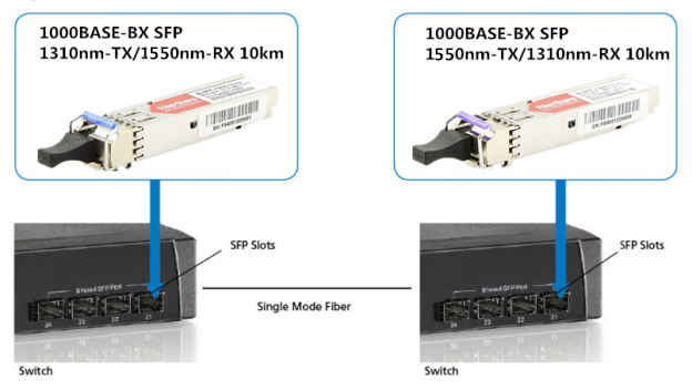
You will never buy two left shoes, but people often make a similar mistake when they’re working with Single Strand Fiber (SSF). Single strand fiber technology allows for the use of two independent wavelengths, such as 1310 and 1550 nm, on the same piece of cable. The most common single strand fiber device is Bi-Directional (BiDi) transceiver. Two BiDi transceiver must be matched correctly. One unit must be a 1310nm-TX/1550nm-RX transceiver (transmitting at 1310 nm, receiving at 1550 nm) and the other must be a 1550nm-TX/1310nm-RX transceiver (transmitting at 1550 nm, receiving at 1310 nm). The 1550nm-TX/1310nm-RX transceiver is more expensive than the 1310nm-TX/1550nm-RX transceiver, due to the cost of their more powerful lasers. So network engineers may hope to save money by installing a pair of 1310nm-TX/1550nm-RX transceivers. But, like mismatched shoes, it doesn’t work.

single-strand-fiber

2. Don’t Use Single-Mode Fiber over Multimode Fiber

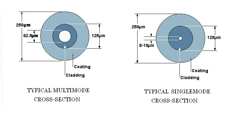
Some people may want to make use of legacy cabling or equipment from an older fiber installation to save cost. But keep in mind that single-mode and multimode fiber are usually incompatible. Multimode fiber uses cable with a relatively large core size, typically 62.5 microns (om2, om3 and om4), and 50 microns (om1) still used in some installations. The larger core size simplifies connections and allows for the use of less powerful, less expensive light sources.  But the light therefore tends to bounce around inside the core, which increases the modal dispersion. That limits multimode’s useful range to about 2 km. Single-mode fiber combines powerful lasers and cabling with a narrow core size of 9/125 microns to keep the light focused.  It has a range of up to 120 km, but it is also more expensive. If you tried to use single-mode fiber over a multimode fiber run.  The core size of the fiber cable would be far too large.  You’d get dropped packets and CRC errors.

single-mode-multimode-fiber

3. Understand All kinds of Fiber connectors First

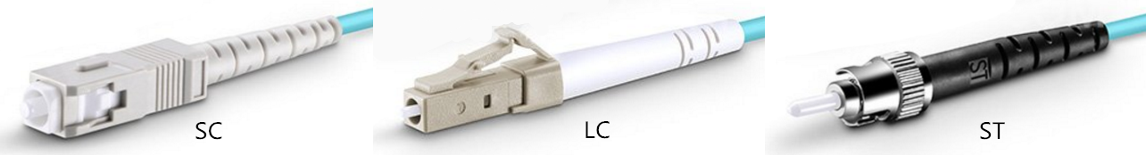
Fiber optic transceivers use a variety of connectors, so make clear their differences before you begin ordering products for a fiber installation is necessary. SC (stick and click) is a square connector. ST (stick and twist) is a round, bayonet-type. LC, or the “Lucent Connector”, was developed by Lucent Technologies to address complaints that ST and SC were too bulky and too easy to dislodge. LC connectors look like a compact version of the SC connector. SFP (small form‐factor pluggable) transceivers usually use LC connector.  Less common connectors include MT-RJ and E2000.

st-lc-sc

4.Connector Links and Splice Times Also Affect 

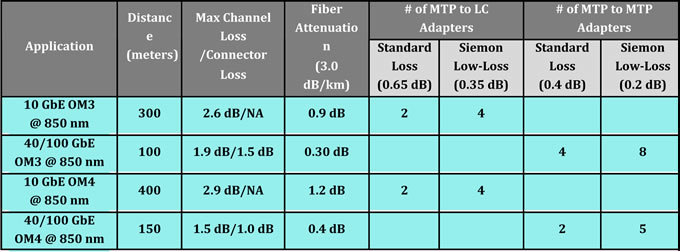
Although single-mode fiber suffers from less signal loss per km than multimode, all fiber performance is affected by connectors and splices. The signal loss at a single connector or splice may seem insignificant. But as connectors and splices become more numerous signal loss will steadily increase. Typical loss factors would include 0.75 dB per connector, 1 dB per splice, 0.4 dB attenuation per km for single-mode fiber and 3.5 dB attenuation per km for multimode fiber.  Add a 3 dB margin for safety. The more splices and connectors you have in a segment, the greater the loss on the line.

5. Don’t Use APC connector with UPC Connector

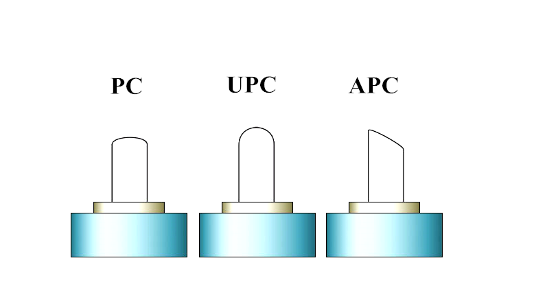
Fiber connections may use Angle Polished Connectors (APC) or Ultra Polished Connectors (UPC), and they are not interchangeable. There are physical differences in the ferules at the end of the terminated fiber within the cable (shown in the figure below).  An APC ferrule end-face is polished at an 8° angle, while the UPC is polished at a 0° angle. If the angles are different, some of the light will fail to propagate, becoming connector or splice loss. UPC connectors are common in Ethernet network equipment like media converters, serial devices and fiber‐based switches. APC connectors are typical for FTTX and PON connections.  ISPs are increasingly using APC.

apc-upc-connector

6. Don’t Connect SFP to SFP+ Transceivers

Small Form Pluggable (SFP) transceivers are more expensive than fixed transceivers.  But they are hot swappable and their small form factor gives them additional flexibility. They’ll work with cages designed for any fiber type and their prices are steadily dropping.  So they have become very popular. Standard SFPs typically support speeds of 100 Mbps or 1 Gbps. XFP and SFP+ support 10 Gbps connections. SFP+ is smaller than XFP and allows for greater port density.  Though the size of SFP and SFP+ is the same, you can’t connect SFP+ to a device (SFP) that only supports 1 Gbps.

Related Article: Optical Module Maintenance Methods and Installation Tips

Low-loss Connectivity For Multimode Fiber Applications

Share

Optical insertion loss budgets are now one of the top concerns among data center managers, especially in today’s large virtualized server environments with longer-distance 40 and 100 gigabit Ethernet (GbE) backbone switch-to-switch deployments for networking and storage area networks (SANs). In fact, loss budgets need to be carefully considered during the early design stages of any data center—staying within the loss budget is essential for ensuring that optical data signals can properly transmit from one switch to another without high bit error rates and performance degradation.

low-loss-multifiber-connectivity

With the length and type of the fiber optic cable and number of connectors and splices all contributing to the link loss, data center managers are faced with the challenge of calculating each connection point and segment within their fiber channels. Multi-fiber push on (MPO) or mechanical transfer push on (MTP) connectors are rapidly becoming the norm for switch-to-switch connections due to their preterminated plug and play benefits and ease of scalability from 10 to 40 and 100 gigabit speeds. Unfortunately, typical MPO MTP module insertion loss may not allow for having more than two mated connections in a fiber channel, which significantly limits design flexibility and data center management. Low loss, rather than standard loss, MPO/MTP connectors better support multiple mated connections for flexibility over a wide range of distances and configurations while remaining within the loss budget.

MTP LC

Typical MPO/MTP connectors, which are required for 40 and 100 GbE eployments have insertion loss values that range from 0.3 dB to 0.5 dB. Typical LC multimode fiber connectors have loss values that range from 0.3 dB to 0.5 dB. While better than the allowed 0.75 dB TIA value, typical connector loss still limits how many connections can be deployed in 10, 40 and 100 GbE channels. For example, with an LC connector loss of 0.5 dB, a 300-meter 10 GbE channel over OM3 fiber can include only three connectors with no headroom. Having just two or three connections prevents the use of cross connects at both interconnection (MDA) and access switches (HDA).

Due to improvements in connector technology and manufacturing techniques, Fiberstore has succeeded in lowering the loss to 0.20 dB for MTP connectors and to 0.15 dB (0.1 dB typical) for LC and SC connectors, well below the industry standard of 0.75 dB and loss values offered by other manufacturers.

For 10 GbE, Fiberstore low loss LC fiber jumpers offer a loss of 0.15 dB (typical 0.1 dB) and Fiberstore low loss plug and play MTP to LC or SC modules offer a loss of 0.35 dB (typical 0.25 dB). For 40 and 100 GbE, MTP to MTP pass-through adapter plates and MTP fiber jumpers offer a loss of 0.2 dB. These lower loss values allow data center managers to deploy more connection points in fiber channels, enabling the use of distribution points or cross connects that significantly increase flexible configuration options.

Table 2 below provides an example of how many connections can be deployed in 10, 40 and 100 GbE channels over OM3 and OM4 multimode fiber using low loss MTP to LC modules for 10 GbE and low loss MTP to MTP pass-through adapters for 40 and 100 GbE versus standard loss solutions.

As indicated in Table 2, the use of low loss connectivity allows for four connections in a 10 GbE OM3 or OM4 channel compared to just two when using standard loss connectivity. Low loss connectivity allows for eight connections in a 100- meter 40/100 GbE channel over OM3 versus just four connections using standard loss, and five connections in a 150-meter 40/100 GbE channel over OM4 fiber compared to just two connections using standard loss. Deploying cross connects between interconnection and access switches requires a minimum of four connections, depending on the configuration. Therefore, cross connects in a full-distance optical channel are simply not feasible without low loss connectivity.

Figures 6, 7 and 8 shows some example scenarios for deploying cross connects in 10 GbE and 40/100 GbE channels over OM3 and OM4 fiber using Fiberstore low loss fiber connectivity. In Figure 6, all changes are made at the cross connect with LC fiber jumpers. The switches remain separate and the permanent MTP trunk fiber cables need only be installed once. The cross connect can be placed anywhere within the channel to maximize ease of deployment and manageability.

MTP Trunk Cable

Figure 7. shows an OM3 40/100 GbE channel with six Fiberstore low loss MTP-MTP pass-through adapter plates and low loss trunks. This scenario offers 0.4 dB of headroom and provides even better manageability and security. All changes are made at the cross connects via MTP fiber jumpers, switches remain separate, and the MTP trunk cables need only be installed once.Once again, the cross connects can be located anywhere in the data center for maximum flexibility. This allows for one-time deployment of high fiber-count cabling from the cross connect at the interconnection switch to the cross connect at the access switch. Adding additional access switches can be accomplished with short fiber runs from the cross connect.

Figure 7: For maximum flexibility, manageability and security, up to eight low loss MTP-MTP pass-through adapters can be deployed using low loss trunks in a 100-meter 40/100 GbE switch-to-switch backbone channel over OM3 fiber.

If the loss budget does not permit deploying six MTP to MTP adapters, one option is to deploy MTP to LC or MTP to MTP jumpers from the cross connect to the equipment, depending on the equipment interface. For example, if using OM4 fiber to extend the channel distance to 150 meters, up to five Low Loss MTP-MTP pass through adapters can be deployed as shown in Figure 8.

Fiber Optics And Cleaning Of Fiber Optic Connectors

Share

Fiber optics can be a revolutionary technology which has transformed the strategies of communication, making data considerably faster. We have which utilizes glass (or plastic) threads (fibers) to send out data. They carry numerous additional benefits as compared with metal wires with regards to data transfer useage. The fiber optic cable is made up of bundle of glass threads, which can do transmitting messages modulated onto light waves. The thin size optical cables makes them easy to set up, greater bandwidths allow greater data and less vunerable to any interference in the signals.

Advantages of fiber optics include:

  •  Faster connection speeds
  •  More bandwidth for phone lines, data transfer, videos, and television
  • Stronger signal over longer distances
  • Clearer phone conversations and video reception

Although benefits are plenty, yet a very important factor that holds importance is cleaning of fiber optic cables. Cleaning is to maintain normal running of the fiber optic method. In optical devices used process, for instance, optical fiber joint activities in various degrees may contamination by dust, dirt, the optical link loss increase, at this point the particular phenomenon seen as optical receiver optical power reduction, optical receiver output level is decreased obviously. In cases like this, the fiber connectors has to be properly clean maintenance. Light always travels in the straight path as well as a slight hindrance in its path can bring about data loss. So, to ensure that there is no data loss in fiber optic communication, it is necessary to clean fiber optics.

Not simply is the cleaning of fiber optics crucial, but the connectors which are utilized to connect the fiber optics need to be maintained and cleaned regularly. Cleaning of fiber optic connectors requires that you have a very little technical knowledge.

The first task in connector cleaning may be the cleaning of Ferrule, a cylindrical element of the connector which is generally comprised of stainless steel. The dwelling of an ferrule contains small holes in which the fiber cables are positioned. The fibers are engraved to suit with all the end face from the ferrule. With the aid of a mating sleeve, the 2 ferrules are contacted with each other within their end faces and additional transmission of sunshine signals comes about. Any blockage or damage in the form of dust or stain can distort the info connection and result in signal loss. So, to make certain that your communication channels are operating smoothly with no interruption inside the data flow you’ll want to perform the cleaning of fiber optical connections and cables with a timely basis.

There are various fiber optic tool kits you can purchase that can be used for cleaning of fiber optic cables installed at your home and also office. The very fact, that cleaning has to be done on a regular basis makes the cleaning kits more important for domestic use. By using these kits, you can save yourself in the need for calling professional cleaning providers when you look to clean your optical connections. FiberStore provide other fiber optic tool,for example Crimping tool,wire cutter etc. You’ll find your optical tools within our store.

Insert Loss And Return Loss For Fiber Connectors

Share

Optical fiber connector is connected to various devices communication systems are essential components, is currently the largest use of optical devices. Since the local optical fiber communication network gradually, metro and access network users increased demand, global fiber optic connector market in recent years, the total demand continues to expand, the annual growth rate over the next decade is expected to be around 20%.

Although there are more than 70 kinds of Fiber Connectors, and new varieties are still emerging. Typically, the measure of product quality fiber optic connector optical characteristics of the main indicators Insert loss and Return loss. In addition, the impact of product quality and reliability ferrule endface geometry and other physical characteristics of the system indicators are increasingly being valued by manufacturers or end customers. The following from the fiber optic connector works starting on the connector insertion and return loss as a brief introduction:

Fiber optic connectors can not be used, it must be the same with other types of connectors with each other, in order to form a light path connections. Insertion loss is the connector connecting the system with an optical power attenuation (i.e., the output power to the optical connector relative to the input power reduction amount). Insertion loss mainly by optical phase between successive two lateral deviation caused. For example, two optical fibers in alignment, laterally offset is zero, then the result of the minimum insertion loss. However, in the actual docking connector, this is unlikely to be achieved, since the core and the fiber cladding misalignment of the fiber cladding and the pin bore and the pin bore misalignment of the outer diameter of the concentric error, etc., will cause lateral deviation between the fibers.

Meanwhile, the fiber optic connector end face quality vertical clearances and insertion loss is caused by one of the factors commonly used in recent years, UPC plug contact way, you can solve the problem of vertical clearance. In this way, pins and fiber end is spherically polished, so that the two pins relative access under the action of external forces engaged with the engaging morph fiber and flattened, forming an optical fiber butt sufficient to reduce fiber connector vertical clearance.

Return loss is a measure of the back end connector to the size of the parameters of reflected light. The essence of the echo that is reflected light, according to Fresnel reflection principle, the light during the transmission encounter two different refractive index interface Fresnel reflection occurs, causing the optical path of the signal is superimposed or interfere. In high data rate systems of single-mode fiber, in particular cable television system (CATV), reflections of the transmitted signal is generated a time lag, so that the signal time delay to reach the client, cause image ghosting and decreased sharpness.

UPC connector connector contact manner, by reducing the gap between the connection end faces, in addition to reducing the insertion loss, but also reduces the connection end of the reflection and improve the return loss; while for other users of the CATV system, APC type contact method was a better choice: Because APC ceramic ferrule type connector end of its spherical axis normal to the fiber at an angle (usually 8 °), so that the light reflected from the end face escape without returning core, thus greatly improving the return loss of the connector.

Other info: Before installing any fiber optic system, you must first consider the approach to low-loss optical fiber or cable to connect to each other in order to achieve the optical link connection. Fiber link connection, can be divided into permanent and activities of two kinds. Permanent connection, they use a fiber splicing method(related:fiber splicer), bonding method or fixed connector to achieve; activity of continuation, the general activities of the connector to achieve.Want to know more fiber connectors info ,pls continue to focus on my blog.

Crimping Tool Types And Operation

Share

The crimping tool is used for creating a joint between two metal pieces or other materials with good malleability. The joint formed by crimping needs to be strong to ensure that the application works properly. Crimping tools are available in different types to support various types of applications. FiberStore is a good crimping tools supplier.  We provide many types of crimping tools in all possible varieties so that the purchasers are able to make the right choice while being in our store.

For example, the structured cabling system lays stress on following the practices which will add elegance, discipline, method and reliability to cabling. The tools which are used in installation of a cabling system go a long way in and can sustain extensive use in the field. Modular Crimping Tool can be used to crimp RJ-45 (related products: rj45 plug) and RJ-11 types of fiber connectors. It is a highly compact and rugged tool and is meant for continuous use in the field. The parallel action design maintains accurate.

Hand operated crimpers are the most frequently used of all cable crimping tools. Most are designed in a basic plier pattern with one or a number of crimping points machined into their jaws. This type of tool is typically used to effect smaller crimps on steel cables, electrical connections and terminations, preinsulated lugs and ferrules, and RJ type plugs. The crimp points on hand crimpers are either half round compression or cup and tab crimp type designs. This type of crimper is generally used to crimp steel or copper ferrules or sleeves to join two lengths of steel or electrical cable.

Types of Crimping Tools

First and foremost, you must offer these them manufactured in different types. Different customers might come and ask for a specific type. learn about different types of tools used for crimping form the below list:

1.Cable tie tools are the crimping tools used to tighten the ties around the bundles of wires or cables.
2.Compression crimp tools are used for terminating twisted-pair modular plugs and coaxial compression connectors.
3.RJ45 crimp tools are used for crimping the wires of various connectors like RJ45, RJ-11, RJ-12 and so on.
4.Point to cup tools are used with round section crimp sleeves. Besides, there are cup to cup tools available in different varieties like standard duty tool, heavy duty tool and bench press tool.

8P8C RJ-45 Network Cable Crimping Tool HT-210C

Crimp Tool Operation

A crimping tool is an essential part of the crimping process, the other parts being the terminal and wire. Terminal size is largely universal and can accept many sizes of gauged wire, which can also vary widely within the same nominative value. As such, the crimp tool is a means of compressing the terminal to both the wire’s insulation (for positioning) and the wire’s brush (for conduction).

The quality of the tooling determines the quality of the crimp design. Common considerations include if the volume of crimping deserves an automated wire stripping and process machine, or if the application is better suited by an on-site, handheld crimping tool. Many tools will have two crimping cavities to properly roll the terminal’s crimps, and possibly more if there are two conductors in the wire. Some crimp tools will feature several gauge sizes and possibly a stripper to enhance the crimper’s utility. Crimp tools may also feature interchangeable dies. Die-less crimpers are meant for general applications.

Fiberstore supplies a wide variety of specialized cable crimping tool, modular crimping tool, network cables crimpers which are all at very competitive price to help you get the job done right. For more information, please contact our sales representative right now.

Related Article: https://www.cables-solutions.com/used-the-crimping-tool-to-made-a-rj45-plug.html

Overview The Ethernet Technology

Share

The term Ethernet in basic terms is cables linked to a network which in-turn send data packets across several networks. Ethernet works by linking computers and other devices through cables. One end of these cables is connected to the computer, and the other is to a connector. These Fiber Connectors could be Repeaters, Hubs or fiber switch.

In the present, the Ethernet technology is available in many versions. The earliest ones are the 10BASE5 (the very first standard), 10BROAD36 (the first standard that allowed long-distance connections), 10BASE2 (also known as the Cheapernet) and 1BASE5 (said to be a failure but started the following developments in Ethernet technology).

The more modernized generation of the technology came with different speed performances. The 10 megabit Ethernet was the first to step out of the previous 1Mbit/second rating. And then the Fast Ethernet, which upholds the rate of 100Mbit per second, dethroned the previous by executing ten times higher.

And then the Gigabit Ethernet was born, priding itself with an even more edgy speed of 1 gigabyte per second data transmission. The Gigabit Ethernet soon opened doors for the 10 Gigabit Ethernet, the variant that surpassed its already-powerful precedent. And today, the public is only waiting for newer versions 40 and 100 Gigabit to be released.

Some Ethernet knowledge you must know. The 10 Mbps protocol continues to be most widely used for most networks, and commonly regarded as ‘Standard Ethernet’ as well as 10BASE-T. Many networks are currently making use of something known as the ‘Fast Ethernet’ which uses a 100 Mbps protocol and is known as 100BASE-T. Finally you will find the 1000 Mbps protocol which is referred to as the ‘Gigabit Ethernet’. Most LAN systems at present use a Fast Ethernet for the main system, and every one of the computer workstations will use particular 100BASE-T or 10BASE-T ethernet card which the LAN facilitates.

The Ethernet is classified making use of international standards, explicitly IEEE 802.3. It makes it possible for the connection of fiber optic cables, up to 1024 coaxial nodes and the twisted-pair cable and the most often used is the Category 5 cable.

The Ethernet functions in such a way that signals are transmitted serially from the primary location to all locations within the network. The Ethernet will make use of a CSMA/CD Carrier Sense Multiple Access/Collision Detection. This implies that all locations will hear all transmissions but is only to listen to the ones that have been meant for it.

Depending on the size your network you are able to select Standard, Fast or GigaByte Ethernet setups. Obviously, the bigger the network the higher the Ethernet setup you need to utilize. If you use the Standard Network but have hundreds of workstations on the network, it may not be able to handle all the transmissions and can have too many collisions which will decelerate everything. Want to have some products to support your Ethernet, like serial to ethernet, ethernet card,ethernet Media Converter and so on. FiberStore maybe can help you.

Many newer versions of Ethernet are updated often as the necessity for more performance primarily based services becomes imperative. The wants of organisations differ and thus does the dimensions of the network. The value for putting in place an Ethernet network depends upon the quantity of computers that is to be connected on the network. The computers therefore connected through the Ethernet network can share a common operating system, security measures and unique identification certificates. It uses special routers, switch or modems for this according to the need or necessity. It wants minimal hardware and that is principally Ethernet cables to connect. It will be used for both wired and wireless interfaces. Even for personal use one will founded the Ethernet affiliation to attach a pair of-three computers among the same home network. Thus it is extremely helpful to form a standard communication network within an area. Knowing what ethernet communications are will be terribly helpful to all technocrats and even the laymen as everyone is using computers at home and within the office.

The Detail For RJ45 Interface Connector

Share

In this network era, the connector has been becoming more and more popular in our life. All kinds of copper wires and fiber optic cables are likely to require corresponding connectors such as RJ45 connectors/plugs and fiber connectors. Here, we focus on the connector for RJ45 Interface involved with RJ45 Ethernet cable.

What Is RJ45 Interface Connector?

Commonly known as “crystal head” given its appearance, RJ45 interface connector is a kind of component that can insert along a fixed direction into a RJ45 interface and can prevent loss of plastic connectors automatically. RJ45 is a kind of network interface specification (similar to RJ11 interface, commonly used as “telephone interface” to connect telephone lines). Crystal head is suitable for the equipment or horizontal subsystem field termination, shell material with high density polyethylene. Both ends of the twisted pair must be installed RJ45 plug to plug the RJ45 connector on the RJ45 interface card (NIC), the hub or switch on RJ45 interface, for network communication. Each of the twisted pair at both ends by installing crystal head with NIC connected to a hub (or switch). RJ45 interface is typically used for data transmission, the most common application interfaces for the network card.

RJ45 Interface Connector

Line Sequence for Network Cable Cords

The RJ45 network cord, made up of a total of eight core, is widely used in LAN and ADSL broadband Internet between network devices for network cable connection. It is often inserted into a RJ45 interface connector to form a RJ45 Ethernet cable.

There are two connection orders  (line sequence) for the eight cores. Normally, the two line sequence were referred to as T568A line order and T568B wire order in the specific application. One order for T568A is white green, green, white orange, blue, white blue, orange, white brown, brown; the other is white orange, orange, white green, blue, white blue, green, white brown, brown.

T-568A-vs.-T-568B

RJ45 Interface Connector Types

Common RJ45 connector can be divided into two categories: DTE type used in Ethernet card, router, etc., and the DCE type used in switches, etc. DTE is called “data terminal equipment”, DCE is known as “data communications equipment”. In a sense, DTE device known as the “active communication equipment”, DCE devices referred to as “passive communication equipment”. When two types of devices using RJ45 interface connection communication, one must use a crossover cable connection.

Conclusion

In network products, network cable and RJ45 connector may be ordinary but necessary. Although Internet cable and crystal head is not important things, but if the quality of cable with crystal head is not good, then you will often meet all kinds of puzzling problem when surfing the Internet for transmission and the exchange of important data. So the choice and buying of cables and crystal head is important as well. By the way, FS.COM offers RJ45 Plugs with high quality and have superior performance in your networking system.

Related Articles:
How to Choose and Buy the Best Ethernet Cable
Difference of Straight Through and Crossover Cable
Patch Cable vs. Crossover Cable: What Is the Difference?
Quick View of Ethernet Cables Cat5, Cat5e And Cat6