Tag Archives: Optical Amplifier

5 Concepts Help Easily Get WDM System

Share

The Wavelength Division Multiplexing (WDM) system is a passive, optical solution for increasing the flexibility and capacity of existing fiber lines in high-speed networks. By adding more channels onto available fibers, the WDM System enables greater versatility for data communications in ring, point-to-point, and multi-point topologies for both enterprise and metro applications. Do you know about WDM system? 5 concepts provided in this blog may help you easily get it.

Optical Transmission
Optical transmission is the conversion of a digital stream of information to light pulses. The light pulses are generated by a laser source (LED or vessel) and transmitted over an optical fiber. The receiver converts the light pulses back to digital information.

Optical Transmission

Wavelength Division Multiplexing
WDM is based on the fact that optical fibers can carry more than one wavelength at the same time. The lasers are transmitting the light pulses at different wavelengths that are combined via filters to one single output fiber. The device used to combine wavelengths is called multiplexer and the device used to separate wavelengths is called demultiplexer, which are the two most basic component in WDM system.

Wavelength Division Multiplexing

Optical Amplifiers
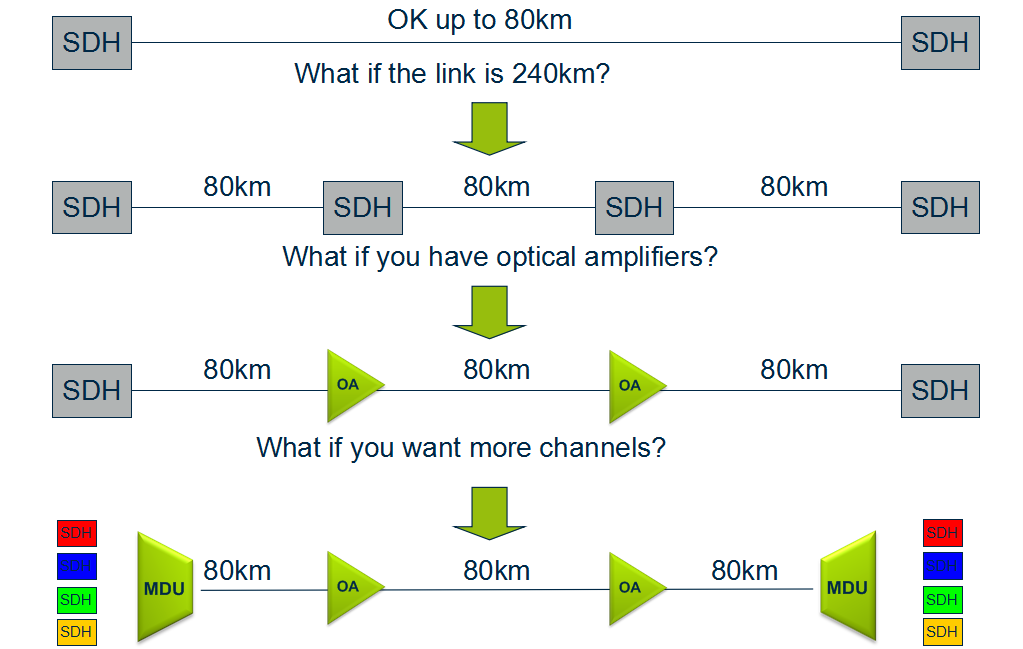
An optical amplifier is a device that amplifies an optical signal directly, without the need to first convert it to an electrical signal. Optical amplifiers boosts the attenuated wavelengths and are more cost efficient than electrical repeaters. Without amplifiers the reach is limited to 80-100km before electrical regeneration. Amplifier stations typically each 80-100km.

optical-amplifiers
Depending on signal types and fiber characteristics, amplifiers are used in DWDM networks and increases the reach of the optical signals up to 3000 km. Amplifiers are an basic building block for a powerful DWDM network.
Optical Amplifiers

Transponder
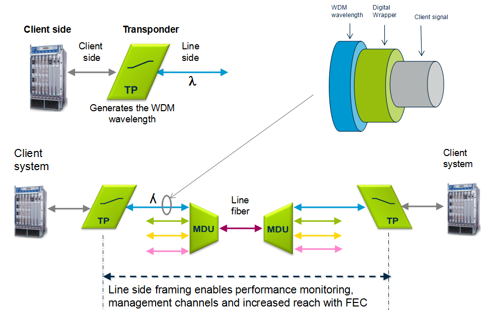
Transponders provides wavelength conversion from client to WDM signal. A transponder maps a single client to a single WDM wavelength. The digital framing of a line signal from a transponder provides service monitoring, management connectivity and increased reach. The broad range of available transponders enables cost efficient solutions for both CWDM & DWDM.
transponder

Optical Add Drop Multiplexer
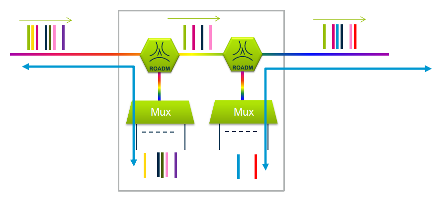
The main function of an optical multiplexer is to couple two or more wavelengths into the same fiber. If a demultiplexer is placed and properly aligned back-to-back with a multiplexer, it is clear that in the area between them, two individual wavelengths exist. This presents an opportunity for an enhanced function, one in which individual wavelengths could be removed and also inserted. Such a function would be called an Optical Add Drop Multiplexer (OADM). OADM is used for increased flexibility in the optical paths. Services can be redirected upon failure or capacity constraints and capacity can be increased dynamically per node.
optical-add-drop-multiplexer

Conclusion
Multiplexer and demultiplexer are the most basic component in WDM system. If your transmission distance is more than 100 km, an optical amplifier is necessary. If your client wavelength isn’t available for WDM applications, you may need a transponder to convert it to WDM available wavelength. Want to achieve a more flexible, just choose to use a OADM. Besides these, sometimes, a dispersion compensation module is also needed to fix the form of optical signals that are deformed by chromatic dispersion and compensates for chromatic dispersion in fiber that causes the light pulses to spread and generate signal impairment. Do you get WDM system? Just start to build your own WDM system now!

Erbium Doped Fiber Amplifier (EDFA) Used in WDM System

Share

The capacity of fiber optical communication systems has undergone enormous growth during the last few years in response to huge capacity demand for data transmission. With the available wavelength division multiplexing (WDM) equipment, commercial system can transport more than 100 channels over a single fiber. However, increasing the number of channels in such systems will eventually result in the usage of optical signal demultiplexing components with greater values of optical attenuation. Besides, when transmitted over long distances, the optical signal is highly attenuated. Therefore, to restore the optical power budget, it is necessary to implement optical signal amplification. This article may mainly tell you  why EDFA is used in WDM system and how does it work.

Why Use EDFA in WDM System?

EDFA stands for erbium-doped fiber amplifiers, which is an optical amplifier that uses a doped optical fiber as a gain medium to amplify an optical signal. EDFA has large gain bandwidth, which is typically tens of nanometers and thus actually it is enough to amplify data channels with the highest data rates. A single EDFA may be used for simultaneously amplifying many data channels at different wavelengths within the gain region. Before such fiber amplifiers were available, there was no practical method for amplifying all channels between long fiber spans of a fiber-optic link. There are practically two wavelength widows C-Band (1530nm-1560nm) and L-Band (1560nm-1600nm). EDFA can amplify a wide wavelength range (1500nm-1600nm) simultaneously, which just satisfies the DWDM application, hence it is very useful in WDM for amplification.

How Does EDFA Work ?

The basic configuration for incorporating the EDFA in an optical fiber link is shown in the picture below. The signals and pump are combined through a WDM coupler and launched into an erbium-doped fiber (EDF). The amplified output signals can be transmitted through 60-100km before further amplification is required.

EDFA
Erbium-doped fiber is the core technology of EDFA, which is a conventional silica fiber doped with erbium ions as the gain medium. Erbium ions (Er3+) are having the optical fluorescent properties that are suitable for the optical amplification. When an optical signal such as 1550nm wavelength signal enters the EDFA from input, the signal is combined with a 980nm or 1480nm pump laser through a wavelength division multiplexer device. The input signal and pump laser signal pass through erbium-doped fiber. Here the 1550nm signal is amplified through interaction with doped erbium ions. This can be well understood by the energy level diagram of Er3+ ions given in the following figure.

EDFA

Where to Buy EDFA for Your WDM System ?

To ensure the required level of amplification over the frequency band used for transmission, it is highly important to choose the optimal configuration of the EDFAs. Before you buy a EDFA, keep in mind that the flatness and the level of the obtained amplification, and the amount of EDFA produced noise are highly dependent on each of the many parameters of the amplifier. Fiberstore provide many kinds of EDFAs, especially the DWDM EDFAs (shown in the picture below), which have many output options (12dBm-35dBm). Besides, they are very professional in optical amplifiers. Whatever doubts you have, they can give a clear reply.

EDFA

Ultra-High-Power Optical Amplifier for FTTH – EYDFA

Share

Background

While the Cable Modem, xDSL, and other forms of broadband access are booming in recent years, Fiber To The Home (FTTH) access is also gradually becoming a project that people are very interested in. The FTTH will eventually realize the “three networks in one” of Telephone, CATV and Internet, when the speed of data transmission can be more than 100 Mbps (200 times faster than the commonly used dial-up Internet access) and bring homes high-definition TV movies and fast online office, etc. FTTH can also solve the problem such as the quality of phone calls, the definition of television and so on.

From the perspective of the world’s situation, the FTTH’s promotion of South Korea and Japan has entered a rapid growth period; North America and Europe has begun to start which brings an optimistic outlook; China, Russia, India and South America is following and speeding up the development. From the perspective of FTTH, the optical communications industry market’s growth potential is still very large.

Applications of High-Power Optical Amplifiers

High-power optical amplifier as one of the basic devices of modern optical communications, is not only the premise of the existence of large-capacity and long-distance all-optical communication networks, but also plays a more and more important role in the process of fiber optic networks’ constantly extending and expanding. At present, in the central office, it usually needs to install more than one optical amplifiers in order to cover larger scope and more users. To take CATV for example, if a medium-sized county needs to send high-quality first-level TV signals to the villages and towns, it generally needs 4 to 8 sets of optical amplifiers. However, if high-power optical amplifiers are used, then only one is enough, which can greatly reduce the cost.

Solutions of High-Power Optical Amplifiers

Traditional Solution using EDFA Technology

One of the solutions for high-power optical amplifiers is to use the traditional general EDFA technology. As shown in the figure below, the signal is amplified at the first stage and then divided into several parts into several EDFAs at the second stage to realize the further ascension of power. The power enlarged in the end can be allocated.

Traditional High-Power Solution using EDFAs

Theare are mainly four problems of this solution:

  • The adoption of multilevel structure will make the optical structure very complex, and due to the adoption of multiple lasers in the internal part, the corresponding control scheme is very complicated.
  • As the multilevel structure has a WDM between the two stages of optical amplifiers, equivalent to bring more insertion loss to the optical path, the noise figure of EDFA amplifiers will deteriorate.
  • In addition, the traditional EDFAs use single mode fiber core pump technology, but high-power single-mode pumped lasers have been greatly restricted on technical and cost.
  • The whole sets of EDFA’s cost is very high and is very expensive.

Better Solution using EYDFA Technology

This ultra-high-power amplifier technology is a multimode cladding pump technology—EYDFA technology, a recently developed new technology that uses the Yb3+ and Er3+ ions doped double-clad fiber. The technology results to the combination of a series of new technologies, new processes and new materials. It is the core technology of ultra-high-power amplifiers and represents the development direction of optical amplifier technologies. While traditional EDFA use single-mode fiber core pump technology to achieve higher output power (which has been greatly limited on the technical and cost), the Er/Yb-Doped Fiber Amplifier (EYDFA) multimode cladding pump technology is the best choice for large output power optical amplifiers. Here is a typical optical structure of EYDFA.

EYDFA Structure

The main advantages of EYDFA are as following:

  • Compared with the single mode fiber core pump technology, multimode cladding pump technology has obvious advantages. The multimode cladding pump technology is to input the pump light to the multimode double-cladding fiber whose cross section are hundreds to thousands of times the single-mode fiber. As a result, at the same input optical density, multimode cladding pump can allow hundreds to thousands of times the single-mode pumped input, easily realizing the optical amplifiers’ high output power or ultra-high output power.
  • Can be realized using a simple optical structure, so the application form is very simple (as shown in the figure below).EYDFA Application Structure
  • The overall cost of the pumps can be greatly reduced.

Fiberstore’s high-power optical amplifier module type products—FTTH-EYDFA series are featured with high output power (17–26 dBm), low noise figure (less than 6 dB @ 1550 nm, 5 dBm input power), wide range of working wavelength (1540–1565 nm), flexible control, high reliability, etc. The output power of high-power optical amplifier is nearing 32 dBm in the laboratory.

Conclusion

Predictably, the widely applications of the ultra-high-power optical amplifiers (EYDFA) will have a profound impact on the development of optical communication, and its market prospect and effectiveness to economic and social present a good trend.

Some Developments that May Occur in the Fiber Amplifier

Share

This page will focus on fiber optic amplifiers?application, and obviously, the introduction of EDFA in a long distance network has been the first, application identified by several telecom’s operators. I just think EDFA’s advantage is that using the existing cable from 565 Mbit/s systems. Into a 2400 Mbit/s without any additional electronic requirement, maybe this is one of the cost/performance ratio advantage of the optical amplifier versus the conventional technologies. Other applications arise from those countries where the telecommunication network infrastructures are poor, or even non existing. In such a situation the possibility to reach a distance in the order of 200km at 140 or 565 Mbit/s makes the use of EDFA more competitive.

Optical amplification has been already successfully tested in various laboratories and field trials in Europe, North America and Japan. Worldwide standards authority is still working on the standardization of EDFA optical amplifier. Major telecom manufactures already supply line terminals with integrated optical amplifier functions. As far as the future submarine links are concerned, it is expected that in a few years, because of optical amplification, the electronical of today submerged repeaters, will be amended by replacing all optical amplifiers.

Well, an example of the power budget calculations at 2400 Mbit/s is given in the annex, where an EDFA system composed by a power amplifier and a pre-amplifier has been considered. In combination with a dispersion shifted submarine fiber optic cable, it belongs to outdoor fiber optic cable. Junction Networks. The massive introduction of SDH systems, and the forecast use of it on the existing cables, has made the use of EDFA technologies achievable also in the junction networks area. In Europe, North America and Japan, this possibility will be limited to the intercity applications.

In connection with the subscriber loop network design, a similar range of products is drawn up by the worldwide industry for the next generation of CATV systems. It is CATV amplifier. In a near future optical transmitters with Booster Amplifier? integrated in the same equipment, will need to be able to transmit up to 60/80 television channels simultaneously, in a cluster of 200/300 subscribers each. The figure showed a?Booster EDFA Optical Amplifier.

edfa

Although CATV amplifier housing employed in current CATV networks is designed to accommodate a return path amplifier, most of today’s CATV system have unactivated return channels. Roughly 20 percent of today’s CATV systems use some fiber optic links to bypass slow amplifier chains in the trunk portion of the network. Service is typically provided to residences and apartments, with relatively limited business locations connected to CATV networks. Similar applications product has WDM amplifier. In-line amplifier, just differ in the range of applications. There is usually only a single CATV operator in a given service area, with nascent competition from microwave and direct broadcast satellite service providers. Television receives only background antennas that are 1 to 2 meters in diameter are used by a small fraction of residential customers. With the fast developments of fiber optical amplifiers, I am very bullish on the trend of it, hope it can be dragged out more widely features and bring more benefits to people.

Related Article:  Which Patch Cable Should I Choose for My Optical Transceiver?

Micrel Launches New Limiting Post Amplifier for 10Gbps FTTH PON Network

Share
Micrel Semiconductor has introduced SY88053CL and SY88063CL limiting post amplifier. Both devices support the expansion of the next generation passive optical network (PON) FTTH XGPON and 10GEPON optical line terminal (OLT) ideal for applications. The product line also applies to support multi-rate applications. Fiber optic transceiver module, the maximum rate is up to 12.5Gbps. Support for Ethernet, Fibre Channel, OTN and OBSAI data rate.
“These new devices offer an impressive number of features including a new level of high bandwidth, high input sensitivity with programmable, wide range SD Assert and LOS De-Assert threshold levels, 4dB of electrical hysteresis, and stable SD Assert and LOS De-Assert timing to meet the stringent requirements of next generation PON network,” stated Tom Kapucija,director of marketing for the high speed communications business, Micrel. “Thesse features enable link efficiency optimization with increased system reach, higher link up-time and higher payload bandwidth.”Vice president for the timing and communications business group, Rami Kanama, said, “As the demand for more data at higher speeds increases, carries need to meet this demand by upgrading their line-side equipment and revamping their networks. Micrel continues its effort in addressing this demand at the device level. Our new optical limiting amplifier delivers speed, performance, and features that is critical to solving technical difficulties facing next generation FTTH, Enterprise, and transport networks. With increased link efficiency, system operators can achieve higher data transmission performance and potentially reduce carries’ CapEx and OpEx.”
Both devices incorporate fast SD Assert and LOS De-Assert times across the entire differential input voltage range of 5mVPP to 1800mVPP which enables improved link efficiency and optimization. In 3mVPP to 30mVPP wide LOS / SD threshold range provides a 4dB electrical hysteresis.  Integrated 50 Ohm input and output impedances optimize high speed signal integrity while reducing external component counts and in turn, cost. TTL compatible JAM input enables a SQUELCH function by routing back the LOS or SD signal.
The SY88053CL enable user adjustable decision threshold adjustment for optimized Bit Erro Rate operation in noisy applications with asymmetrical noise distribution while the SY880563CL provides a user selectable Digital Offset Correction function that automatically compensates for internal device offsets in the high speed data path. Other features include multi-rate 1Gbps to 12.5Gpbs operations, optional LOS or SD output, selectable RXOUT +/ RXOUT- signal polarity (SY88053CL) and 25ps typical rise / fall time. Beyond the current customer demand through increased performance margins, improved manufacturability of the module, while reducing costs. By increasing each node and the downstream branch exceeds 512ns link budget margin established, to improve the efficiency and data throughput of the link. By optimizing in a noisy environment and the error rate or RAMAN EDFA Optical Amplifier noise characteristics of asymmetric compensation, expanding the system extends the scope to improve the data throughput.
Both devices offer a wide power supply range of 3.3V+/-10 percent and come in an industrial temperature range of -40 degC to +85-degC and a tiny 3mm x 3mm QFN package.
Source: www.fs.com/news/