Category Archives: Optical Solutions

PCI vs PCI Express: What’s the Difference?

Share

PCI Vs PCI Express are two different versions of internal bus standards for connecting or injecting peripheral devices into equipment like computers, network servers. But do you know about their relations? And could you tell the differences in PCI Vs PCI Express? To figure out these questions, an exploration for PCI and PCI Express will be introduced in this post.

What Does PCI Vs PCI Express Stands for?

What Is PCI?

PCI, also called peripheral component interconnect, is a connection interface standard developed by Intel in 1990. Originally, it was only used in servers. Later on from 1995 to 2005, the PCI was widely implemented in computer and other network equipment like network switch. Most commonly, PCI is used as the PCI-based expansion card to insert into the PCI slot in a motherboard of a host or server. In the expansion card market, the popular PCI expansion cards are NIC card or network interface card, graphics card, and sound card.
What Is PCI Express?
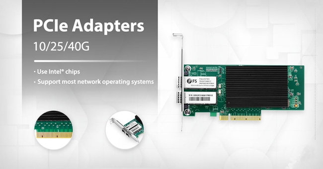
PCI Express Network Card

Figure 1: PCI Express Network Card

PCI Express, also abbreviated as PCIe, refers to the peripheral component interconnect express. As the successor of PCI, PCI Express is also a type of connection standard carried out by Intel in 2001, which provides more bandwidth and is more compatible with existing operating systems than PCI. Similar like PCI, PCIe also can be used as expansion cards like PCIe Ethernet card to insert into PCI Express slot.

Comparison of PCI Vs PCI Express

As the replacement of PCI, PCI Express differs with it in several aspects, such as working topology and bandwidth. In this part, a brief comparison of PCI Vs PCI Express will be made.

PCI Vs PCI Express in Working Topology: PCI is a parallel connection, and devices connected to the PCI bus appear to be a bus master to connect directly to its own bus. While PCIe card is a high-speed serial connection. Instead of one bus that handles data from multiple sources, PCIe has a switch that controls several point-to-point serial connections.
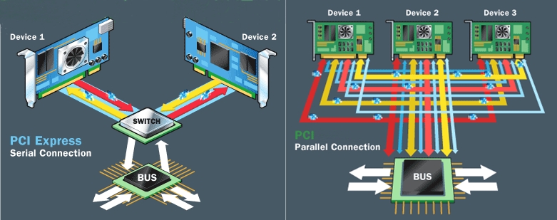
PCI Vs PCI Express

Figure 2: PCI Vs PCI Express

PCI Vs PCI Express in Bandwidth: Generally, the fixed widths for PCI are 32-bit and 64-bit versions, running at 33 MHz or 66 MHz. 32 bits with 33 MHz, the potential bandwidth is 133 MB/s, 266 MB/s for 66 MHz, and 532 MB/s for 64 bits with 66 MHz. As for PCIe card, the bandwidth varies from 250 MB/s to several GB/s per lane, depending on its card size and version. For more detail, you can refer to the post: PCIe Card Tutorial: What Is PCIe Card and How to Choose It?

PCI Vs PCI Express in Others: With PCI Express, a maximum of 32 end-point devices can be connected. And they support hot plugging. While hot-plugging function is not available for PCI, it can only support a maximum of 5 devices.

FAQs About PCI Vs PCI Express

1. Is the speed for PCI slower than PCI Express?

Sure, the speed for PCIe is faster than PCI. Take the PCIe x1 as an example, it is at least 118% faster than PCI. It’s more obvious when you compare the PCIe-based video card with a PCI video card, the PCIe video card x16 type is almost 29 times faster than PCI video card.

2. Can PCI cards work in PCIe slots?

The answer is no. PCIe and PCI are not compatible with each other due to their different configurations. In most cases, there are both PCI and PCIe slots on the motherboard, so please fit the card into its matching slot and do not misuse the two types.

3. What is a PCIe slot?

PCIe slot refers to the physical size of PCI Express. By and large, there are four slot types: x16, x8, x4, and x1. The more the slot number, the longer the PCIe will be. For example, PCIe x1 is 25 mm in length, while PCIe x16 is 89 mm.

Summary

In this post, we make a comparison in PCI Vs PCI Express from their origin, working mode to their bandwidth, etc. In the final part, there are several frequently asked questions listed for your information. Hope this post will give you some inspiration in telling PCI Vs PCI Express.

How to Build Affordable 10G Network for Small and Midsize Business?

Share

With the fast development of today’s networking field, many people tend to build 10G network in small and midsize business for their growing network needs. Then, why they choose 10G network? How to build an affordable one? If you want to build such a network, what things you should know? Don’t worry. Let’s find all the answers in the following text.

Necessity of 10G network

Actually, the necessity of 10G network is quite simple to understand. As time goes on, there will be more traffic and applications running on your existing networks and they will keep growing. At that time, the common used Gigabit network will no longer satisfy the urgent needs for higher networking speeds and larger network construction.

How to Build An Affordable 10G Network?

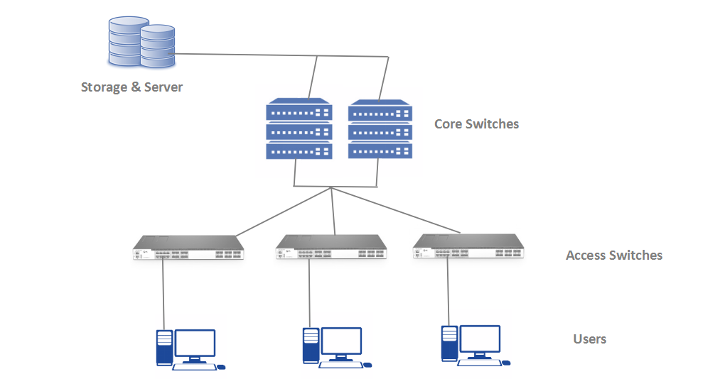
To build a 10G network, there are several indispensable components you need, such as 10GbE switch (10G core switch and access switch with 10G uplinks), 10G SFP+ modules, fiber cables, severs and storage devices, etc.

10G network layout

To build an affordable 10G network for small and midsize business (SMB), let’s take fiber cabling solution as an example.

Fiber Cabling Solution for 10G Network

Under such circumstance, the server or storage has 10G SFP+ port. And it is suitable for applications matching with a 10G fiber switch as the core switch. You can connect all the devices with the steps below:

Step 1: Connect Server Or Storage to A Core Switch

For connection between server (or storage) and a core switch, you can insert a 10G transceiver module connecting with one end of a LC cable into the server or storage, and then connect the other end of the LC cable with the core switch.

Here, the transceiver we use is 10G SFP+ module provided by FS.COM. It can reach a maximum cable distance of 300m over OM3 multimode fiber (MMF).

The LC cable we use is LC UPC to LC UPC duplex OM3 MMF, which has less attenuation when bent or twisted compared with traditional optical fiber cables and will make the installation and maintenance of the fiber optic cables more efficient.

What’s more, the core switch we use is FS S5850-48S2Q4C. This network switch is a 48-port 10Gb SFP+ L2/L3 carrier grade switch with 6 hybrid 40G/100G uplink ports. It is a high performance top of rack (ToR) or leaf switch to meet the next generation metro, data center and enterprise network requirements.

Step 2: Connect the Core Switch With An Access Switch

Next, you need to connect the core switch with an access switch. Just like step 1, insert a 10G transceiver module connecting with one end of a LC cable into the core switch, and then connect the other end of the LC cable with the access switch.

Here, we use FS Gigabit Ethernet switch with 10G SFP+ uplink as the access switch. This is a fanless switch, which is suitable for quilt requirement in SMB network. In addition, it has 24 10/100/1000BASE-T ports and 4 10Gb SFP+ ports for uplinks.

And the LC cable and 10G transceiver we use are the same as the products used in step 1.

Step 3: Connect Your Access Switch to Computers

After the previous two steps, you can use Cat5 or Cat5e cable (here we use Cat5e) to connect your access switch with computers or other devices you need to use. Just remember that you have to connect the 10/100/1000BASE-T ports rather than the 10Gb SFP+ ports.

Products
Price
Features
From US$16.00
Supports 8 Gbit/s Fibre Channel, 10 Gigabit Ethernet and Optical Transport Network standard OTU2.
From US$1.4 to 5.3 for 1m
OM3 10Gb 50/125 multimode fiber
US$5,699.00
48 x 10Gb + 2 x 40Gb + 4 x 100Gb ports; Non-blocking bandwidth up to 960Gbps
US$279.00
24 x 100/1000BASE-T + 4 x 10GB SFP+ ports; Switching capacity up to 128Gbps
Start from US$0.82 for 6in
Shielded (STP) or Unshielded (UTP) Cat5e Ethernet network patch cable (24/26AWG, 100MHz, RJ45 connector)

Conclusion

From all the above, you may get clearer about how to build affordable 10G network for small and midsize business with 10GbE switch, fiber cables, Ethernet cables, etc. As long as you use the right way, you can not only build an affordable 10G network but also a powerful network for future network reconstruction.

Related Articles:

How to Build a 10G Home Fiber Network?

How to Build 10GbE Network for Small and Mid-Sized Business?

SFP Slot Definition and Its User Guideline

Share

It is obvious that optical transceiver is widely used in telecommunication and data center. Speaking of this, SFP module is inevitably involved. However, have you ever heard of SFP and SFP slot? Do you have any idea about how to use SFP slots? If not, read through this post to find what SFP slot is and how to use it.

What Is SFP Slot?

What is SFP port/slot? To figure this out, you must know what SFP is in the first place.

SFP, an acronym of small form-factor pluggable, is a compact and hot-pluggable transceiver used for both telecommunication and data communication applications. It connects motherboards of network devices (such as switches and routers) with optical or copper cables. By doing this, it converts Gigabit electrical signals into optical signals, and vice versa.

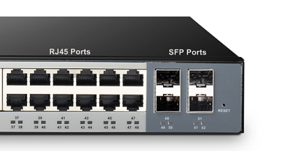
Therefore, just as its name implies, SFP slot is designed for use with SFP transceivers or modules. It offers a place where a SFP transceiver can plug into and then support fiber connection or copper cable connection. Different connection can support different transmission speed and distance. Normally, a Gigabit SFP inserted into a SFP port can reach a speed of up to 1 Gbps!

what is sfp slot

How to Use the SFP Slot?

SFP slot is also known as SFP port. Thus, this question can be referred to as how to use SFPs with SFP ports. SFP and SFP port usually work in pairs. That is to say, you should use SFP slot with a corresponding SFP. Normally, optical transceivers used in SFP slots can be divided into optical and copper SFPs. They can be used on a wide variety of products and intermixed in combinations of 1000BASE-T, 1000BASE-SX, 1000BASE-LX/LH, 1000BASE-EX, 1000BASE-ZX, or 1000BASE-BX10-D/U on a port-by-port basis.

The common match for SFP ports are copper SFP module applied with network cable and fiber SFP module applied with fiber optic cable. Network cable or copper cable includes Cat5e, Cat6, Cat6a, etc. While, fiber optic cable includes single mode fiber and multimode fiber. Therefore, if you want to know how to use SFP slot, you need to know how to choose right copper SFP modules or fiber SFP modules for SFP slots. As for how to choose the right SFP modules, go ahead for more details in the next two paragraphs.

Copper SFP module for SFP Slot

A copper SFP module inserted into a SFP port has a RJ45 connector. It can transmit data within 100m over copper twisted pair cable. And the data transmission rate can reach up to 1000 Mbps. It is normally divided into two types, 1000BASE-T and 1000BASE-TX copper SFP. The former uses the IEEE 802.3ab standard using four bidirectional copper pairs, and each pair supports a data rate of 250 Mbps. While, the latter uses the TIA/EIA-854 standard using two unidirectional copper pairs (one pair for transmitting, one for receiving), each of which supports a data rate of 500 Mbps.

Fiber SFP module for SFP Slot

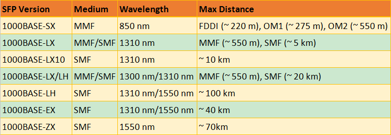
A fiber SFP module inserted into a SFP port has a LC duplex interface. It consists of seven types, namely 1000BASE-SX, 1000BASE-LX, 1000BASE-LX10, 1000BASE-LX/LH, 1000BASE-LH, 1000BASE-EX and 1000BASE-ZX. They are used under different circumstances shown in the picture below:

sfp-ports-with-fiber-sfp-modules

Conclusion

From all the above, you may have a general understanding of what a SFP slot is and how to use it properly. SFP ports are found in Ethernet switches, routers, firewalls and network interface cards, etc. If you want to transfer data in 100m, then either a copper SFP or fiber SFP is a right choice to match the SFP port. If you want to transfer data over 100m, then a fiber SFP is needed.

Related articles:

Can I Connect Fiber Optic Transceivers of Different Brand?

Understanding Combo SFP Port on Ethernet Switch

Copper 10GBASE-T Switch Recommendation

Share

In the past few years, network speeds have increased dramatically as applications like video and technologies like virtualization need higher speed and performance. Therefore, 10 Gigabit Ethernet (10GbE) is widely deployed for inter-switch and server-to-switch links. Generally, there are two 10G switch solutions for the aforesaid 10GbE link: 10GBASE-T switch for copper and 10G SFP+ switch. And since the 10GbE copper switch is more favored by the market, this post will focus on copper10GBASE-T  network switch recommendation.

10GBASE-T Switch vs SFP+ Switch: Why Choose 10GBASE-T Copper Link?

Many people may wonder why 10GBASE-T copper link is more favored by the market. This part will discuss this topic in a brief way.

As we all know, copper 10GBASE-T switch uses copper cables to transmit 10Gbps data. This may help to save much money because copper cable infrastructure is far less expensive than the fiber optics of 10G SFP+ switch. In addition, 10GBASE-T network is easier to be employed and allows users to make the best of their existing Cat6a UTP structured cabling ecosystem. Despite all this, 10G SFP+ link also has such advantages as lower latency and lower power budget. For detailed information, you may read 10GBASE-T VS SFP+: Which to Choose for 10GbE Data Center Cabling.

10GBASE-T Switch Recommendation for Copper

Since 10GBASE-T network is favored by many IT managers, lots of cheap 10GB switch for copper has been supplied in the market. These switches are either 2/4/8/16 port copper switch for home networks or 20+ port 10GBASE-T switch for enterprise and data center networks. This part will introduce a high performance 48 port 10GBASE-T copper switch with 40Gbe QSFP+ UpLink – S5850-48T4Q – for your reference.
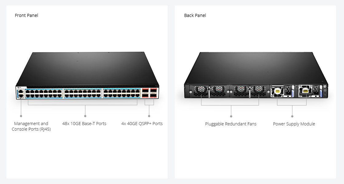
Copper 10GBASE-T Switch

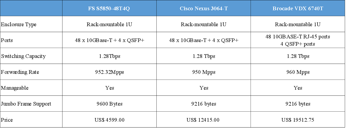
S5850-48T4Q is a 1U managed L2/L3 Ethernet switch. It is designed to meet next generation Metro, Data Center and Enterprise network requirements. Featuring 48 10GBASE-T RJ-45 ports and 4 40G QSFP+ ports, it can provide 1.28Tbps switching capacity. And it has a forwarding rate of 952.32Mpps. The following table compares the key parameters and prices of S5850-48T4Q and other similar switches:

48 port 10GBASE-T Copper Switches

Seen from the above table, you may find that the ports and performance of the three copper 10GBASE-T switches are nearly the same, but Cisco Nexus 3064-T and Brocade VDX 6740T switches are much more expensive than the S5850-48T4Q. This is because their prices include both the actual value of the switch and their specific brands which are always costly. And their after-sale services may be better than most small companies. However, this FS S5850-48T4Q switch is also guaranteed with free tech support and back up support.

S5850-48T4Q 10GBASE-T Switch for Spine-Leaf Application

Unlike most copper 10GBASE-T switches, S5850-48T4Q can be used for Spine-Leaf network which is a popular architecture design for data center. To be specific, S5850-48T4Q is often used as the leaf switch in a 40G Spine-Leaf design. As shown below, the 4OG QSFP+ ports of S5850-48T4Q often used to connect to the spine switch (S8050-20Q4C). And the 10GBASE-T copper ports are connect to servers and routers. Read more about Building Spine-Leaf Network with 10GBASE-T Switch

ToR

Conclusion

For lower cost and ease of use, copper 10GBASE-T switch is popular among 10Gb switches. If you plan to migrate to 10GbE network, 10GBASE-T copper network is a good choice. It will help to reduce the cost complexity and cabling issues around the migration to 10GbE in the data center.

Related Article:

Unique Advantages of 10GBASE-T in Migrating Data Center to 10Gb

FS 10GBASE-T Switch: Breaks the Price Barrier for 10G Network 


Cloud vs Data Center: What’s the Difference?

Share

Many people may be confused about what is cloud computing and what is data center. They often ask questions like, “Is a cloud a data center?”, “Is a data center a cloud?” or “Are data center and cloud computing two completely different things?” Maybe you know your company needs the cloud and a date center. And you also know your data center needs the cloud and vice versa. But you just don’t know why! Don’t worry. This essay will help you have a thorough understanding of the two terms and tell you the difference between cloud vs data center. Let’s begin with their definition first.

Cloud vs Data Center: What Are They?
cloud computing vs data center

The term “data center” can be interpreted in a few different ways. First, an organization can run an in-house data center maintained by trained IT employees whose job is to keep the system up and running. Second, it can refer to an offsite storage center that consists of servers and other equipment needed to keep the stored data accessible both virtually and physically.

While the term “cloud” or “cloud computing” didn’t exist before the advent of Internet. Cloud computing changes the way businesses work. Rather than storing data locally on individual computers or a company’s network, cloud computing entails the delivery of data and shared resources via a secure and centralized remote platform. Rather than using a company’s own servers, it places its resources in the hands of a third-party organization that offers such a service.

Cloud vs Data Center in Security
Cloud Computing vs Data Center

Since the cloud is an external form of computing, it may be less secure or require more work to ensure security than a data center. Unlike data centers, where you are responsible for your own security, you will be entrusting your data to a third-party provider that may or may not have the most up-to-date security certifications. If your cloud are placed on several data centers in different locations, each location will also need the proper measures to ensure the security.

A data center is also physically connected to a local network, which makes it easier to ensure that only those with company-approved credentials and equipment can access stored apps and information. The cloud, however, is accessible by anyone with the proper credentials anywhere that there is an Internet connection. This opens a wide array of entry and exit points, all of which need to be protected to make sure that data transmitted to and from these points are secure.

Cloud VS Data Center in Cost
difference between cloud vs data center

For most small businesses, cloud computing is a more cost-effective option than a data center. Because when you chose a data center, you have to build an infrastructure from the start and will be responsible for your own maintenance and administration. Besides, a data center takes much longer to get started and can cost businesses $10 million to $25 million per year to operate and maintain.

Unlike a data center, cloud computing does not require time or capital to get up and running. Instead, most cloud computing providers offer a range of affordable subscription plans to meet customers’ budget and scale the service to their actual needs. And data centers take time to build,  whereas cloud services are available for use almost immediately after registration.

Conclusion

Going forward, cloud computing services will become increasingly attractive with a low cost and convenient service. It creates a new way to facilitate collaboration and information access across great geographic distances while reducing the costs. Therefore, compared cloud computing vs data center, the future of cloud computing is definitely much brighter.

Related Article: The Evolution of Data Center Switching

How to Handle Challenges of CWDM Network Testing?

Share

CWDM technology has proven itself to be a cost-effective and simplified method for network managers to optimize the existing infrastructure. The adoption of CWDM system into metro and regional network is constantly on the rise and it also extends the reach to the access networks. CWDM is becoming more widely accepted as an important transport architecture owing to its lower power dissipation, smaller size, and less cost. This article will focus on the challenges concerning CWDM network testing, and provide several methods to help overcome them.

Basic Configurations of CWDM Network

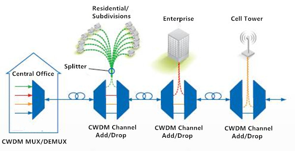
CWDM configuration is usually based on a single-fiber pair: one fiber is for transmitting and the other for receiving. The following figure shows the most basic configuration of optical network with 4 channel CWDM MUX/DEMUX: it often delivers eight wavelengths, from 1471 nm to 1611 nm, with 20 nm apart. A CWDM architecture is quite simple. It only has passive components like multiplexers and demultiplexers, without any active elements such as amplifiers. However, using CWDM as a means of increasing bandwidth also brings network characterization and deployment challenges, which will be discussed in the following section.

cwdm basic configuration

Challenges and Solutions for CWDM Testing

The challenges of CWDM network testing mainly lie in three phases: construction and installation, system activation and upgrade or troubleshoot. Here we provide solutions for each.

Challenge One: Construction and Installation

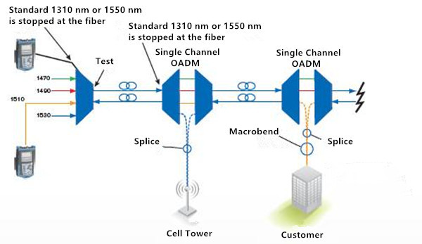
During construction and installation process, it is essential to conduct physical-layer tests on the fiber from the head-end to the destination. Single-ended testing with an OTDR is definitively an advantage as it optimizes labor resources. In this case, the objectives are to characterize the entire link (not only the fiber) to include the add-drop multiplexers (OADM) and to guarantee continuity up to the final destination. However, testing at standard OTDR wavelengths, such as 1310 nm and 1550 nm, cannot be done in such conditions as these wavelengths are filtered out at either OADM, never reaching the end destination. Then how to test such a link?

cwdm otdr testing

Solution: Adopting a specialized CWDM OTDR. With CWDM-tuned wavelength, the CWDM OTDR is capable of performing an end-to-end test by dropping each test wavelength at the correspondent point on the network, allowing the characterization of each part of the network directly from the head-end. Which is considered time and labor saving since one don’t have to access. It also helps to speed up the deployment process as the technician will test all drop fibers from a single location.

Challenge Two: System Activation

Since CWDM network architecture is rather basic which contains no active components like amplifiers, the only things that can prevent proper transmission in a CWDM network system are transmitter failure, sudden change in the loss created in an OADM or manual errors, bad connections for example. To deal with these problems, one has to look at the signal being transmitted.

Solution: A CWDM channel analyzer is ideal to handle this challenge. It works to quickly determine the presence or absence of each of the 16 wavelengths and their power levels. Many CWDM OADM have tap ports, which means that there is a port where a small portion of the signal is dropped. Taps are typically 20 dB weaker than the main signal. If these taps are not present, a CWDM analysis should be performed. It consists of unplugging the end user to use the main feed for the analysis. To be ready for all possibilities, a CWDM channel analyzer should cover a power range going as low as –40 dBm, while being able to test the entire wavelength range in the shortest time as possible.

Challenge Three: Upgrade or Troubleshoot

In the maintenance and troubleshoot phrase, when the network is live and a new wavelength is added, one should figure out two questions: is the link properly set up? And is my wavelength presents and well?

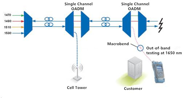
out-of-band testing of cwdm

Solution: Two approaches are available to check if a link is set up properly: a CWDM OTDR approach or an out-of-band approach. The CWDM OTDR approach is relatively simple when a new customer is added. With CWDM OTDR, one can perform CWDM network testing without having to wait for the customer or to go to the cell tower sites. The wavelength can be turned on at the head-end. Which speed testing process greatly.

The OTDR and channel analyzer combo are also useful when a single customer has issues. The channel analyzer will reveal if the channel is indeed present and within power budget. If not, the CWDM OTDR can be used to test at that specific wavelength or an out-of-band 1650 nm OTDR test can be performed from the customer’s site to detect any anomalies on the link, all without disconnecting the head-end since the OADM will filter out the 1650 nm, therefore not affecting the remainder of the network.

Conclusion

CWDM testing challenges may be inevitable during each phase of the deployment, but with specialized equipment, these challenges can be overcomed completely. Tools including a CWDM OTDR, a CWDM channel analyzer and an out-of band OTDR are proved effective and valuable to reduce downtime and increase bandwidth at a minimum cost.

5 Concepts Help Easily Get WDM System

Share

The Wavelength Division Multiplexing (WDM) system is a passive, optical solution for increasing the flexibility and capacity of existing fiber lines in high-speed networks. By adding more channels onto available fibers, the WDM System enables greater versatility for data communications in ring, point-to-point, and multi-point topologies for both enterprise and metro applications. Do you know about WDM system? 5 concepts provided in this blog may help you easily get it.

Optical Transmission
Optical transmission is the conversion of a digital stream of information to light pulses. The light pulses are generated by a laser source (LED or vessel) and transmitted over an optical fiber. The receiver converts the light pulses back to digital information.

Optical Transmission

Wavelength Division Multiplexing
WDM is based on the fact that optical fibers can carry more than one wavelength at the same time. The lasers are transmitting the light pulses at different wavelengths that are combined via filters to one single output fiber. The device used to combine wavelengths is called multiplexer and the device used to separate wavelengths is called demultiplexer, which are the two most basic component in WDM system.

Wavelength Division Multiplexing

Optical Amplifiers
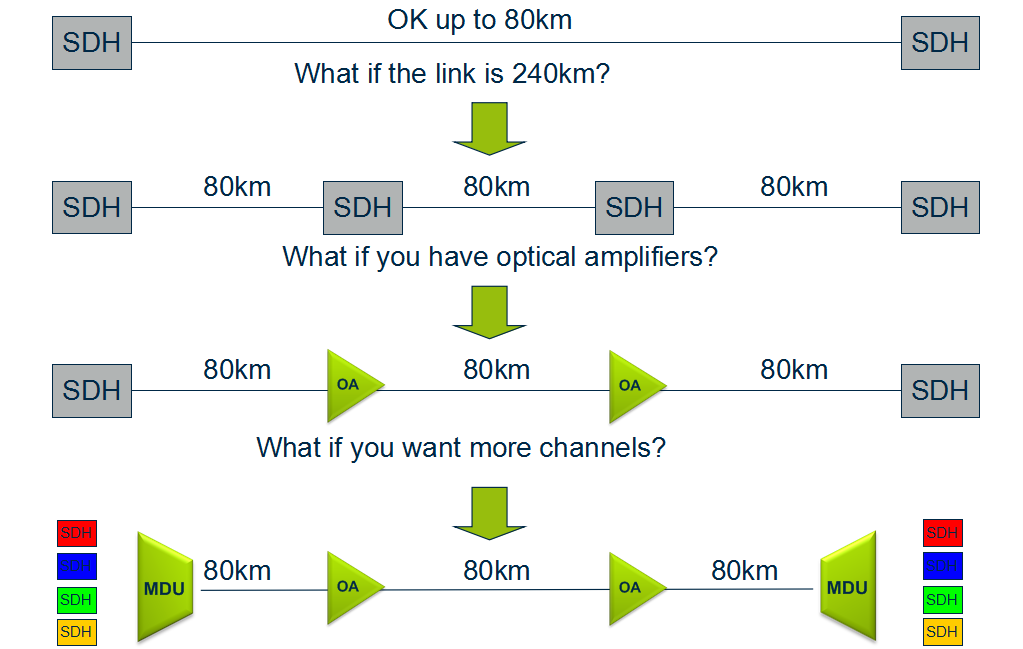
An optical amplifier is a device that amplifies an optical signal directly, without the need to first convert it to an electrical signal. Optical amplifiers boosts the attenuated wavelengths and are more cost efficient than electrical repeaters. Without amplifiers the reach is limited to 80-100km before electrical regeneration. Amplifier stations typically each 80-100km.

optical-amplifiers
Depending on signal types and fiber characteristics, amplifiers are used in DWDM networks and increases the reach of the optical signals up to 3000 km. Amplifiers are an basic building block for a powerful DWDM network.

Optical Amplifiers

Transponder
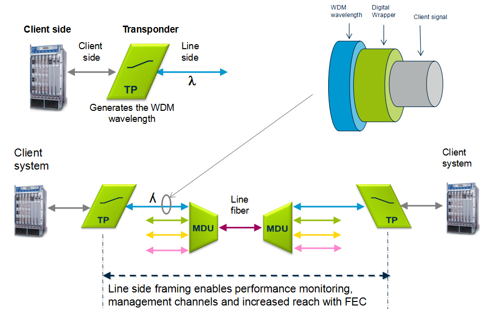
Transponders provides wavelength conversion from client to WDM signal. A transponder maps a single client to a single WDM wavelength. The digital framing of a line signal from a transponder provides service monitoring, management connectivity and increased reach. The broad range of available transponders enables cost efficient solutions for both CWDM & DWDM.

transponder

Optical Add Drop Multiplexer
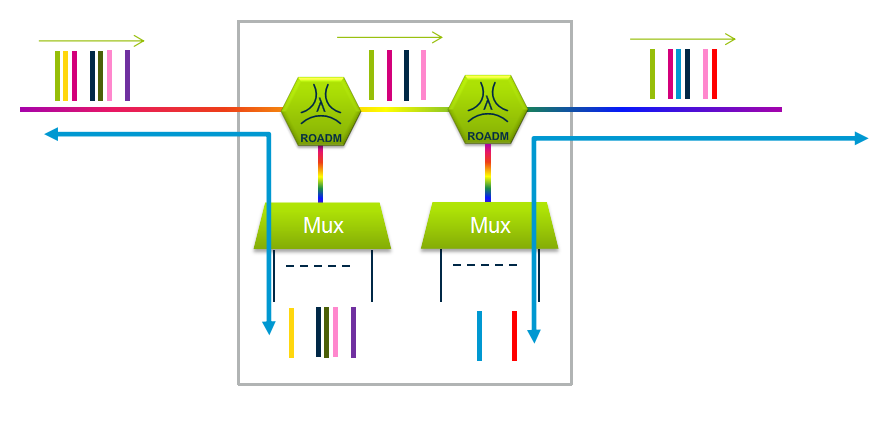
The main function of an optical multiplexer is to couple two or more wavelengths into the same fiber. If a demultiplexer is placed and properly aligned back-to-back with a multiplexer, it is clear that in the area between them, two individual wavelengths exist. This presents an opportunity for an enhanced function, one in which individual wavelengths could be removed and also inserted. Such a function would be called an Optical Add Drop Multiplexer (OADM). OADM is used for increased flexibility in the optical paths. Services can be redirected upon failure or capacity constraints and capacity can be increased dynamically per node.

optical-add-drop-multiplexer

Conclusion
Multiplexer and demultiplexer are the most basic component in WDM system. If your transmission distance is more than 100 km, an optical amplifier is necessary. If your client wavelength isn’t available for WDM applications, you may need a transponder to convert it to WDM available wavelength. Want to achieve a more flexible, just choose to use a OADM. Besides these, sometimes, a dispersion compensation module is also needed to fix the form of optical signals that are deformed by chromatic dispersion and compensates for chromatic dispersion in fiber that causes the light pulses to spread and generate signal impairment. Do you get WDM system? Just start to build your own WDM system now!

Full CWDM Mux Demux and CWDM SFP Transceivers Solutions

Share

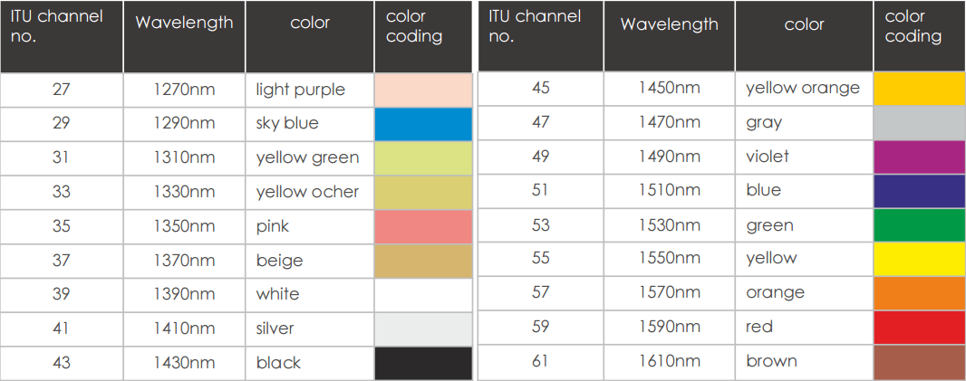
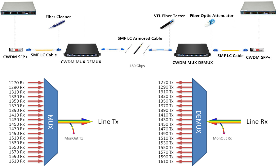
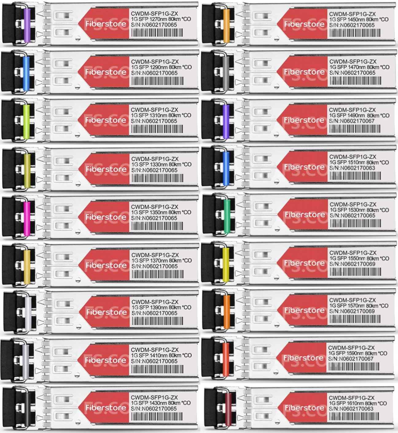
CWDM systems have channels at wavelengths spaced 20 nanometers (nm) apart, compared with 0.4 nm spacing for DWDM. This allows the use of low-cost, uncooled lasers for CWDM. In a typical CWDM system, laser emissions occur on full eighteen channels at eighteen defined wavelengths: 1610 nm, 1590 nm, 1570 nm, 1550 nm, 1530 nm, 1510 nm, 1490 nm, 1470 nm, 1450 nm, 1430 nm, 1410 nm, 1390 nm, 1370 nm, 1350 nm, 1330 nm, 1310 nm, 1290 nm, 1270 nm. Besides, for CWDM systems an industry standard color coding scheme is used. The latches of the CWDM SFP transceivers match the colored port indicators on the passive units therefore guaranteeing simple setup. Following color codes and wavelength are valid for CWDM.

cwdm-channels

Full CWDM Channels (18 Channels) Mux Demux Solution

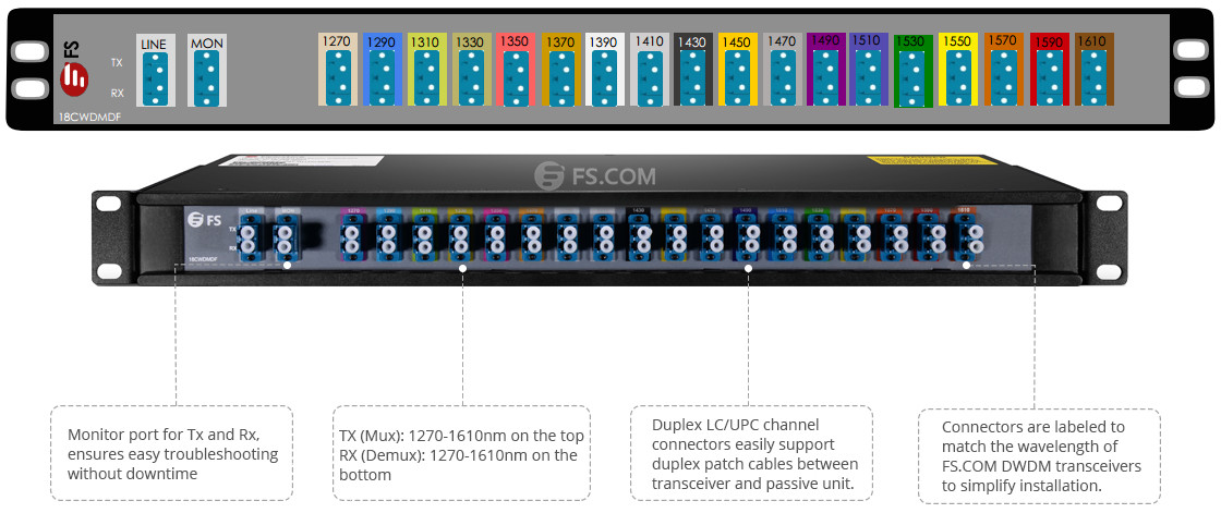
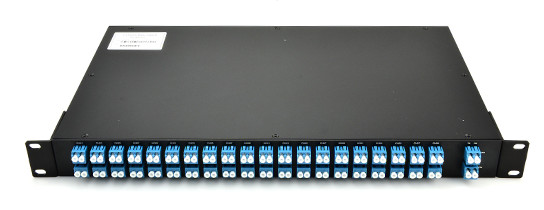
The WDM system uses a multiplexer at the transmitter to combine several wavelengths together, each one carry different signal with bite-rate up to 10G and a demultiplexer at the receiver to split them apart. Both mux and demux are passive, requiring no power supply. The 18 Channels CWDM mux demux covers all channels of 1270nm to 1610nm in 20nm increments. Without replacing any infrastructure, it totally support data rates up to 180 Gbps by being completely protocol transparent. The main fields of applications are the use in SDH (STM-1, STM-4, STM-16, STM- 64), IP (Fast Ethernet, Gigabit Ethernet, 10 Gigabit) ATM and storage (1G, 2G, 4G, 8G, 10G Fibre Channel) networks. Connectors, located on the front of the CWDM mux demux modules, are labeled and use the same color-coding that is used to indicate the wavelength of the individual CWDM SFP transceivers (shown in the figure below).

cwdm-mux-demux

When fiber availability is limited, CWDM mux demux could increase the bandwidth on the existing fiber infrastructure. By using 18ch CWDM mux demux mentioned above and the CWDM SFP transceivers, up to 180 Gbps could be supported on a fiber pair.

18-channels-cwdm-mux-demux

Full CWDM SFP Transceivers Solution

CWDM SFP transceiver is based on the SFP form factor which is a MSA standard build. The max speed of this product is 1.25G and they are also available as 2.5G and of course the popular CWDM 10G SFP transceivers. The CWDM SFP transceiver has a specific laser which emits a “color” defined in the CWDM ITU grid. The CWDM ITU grid is defined from 1270 to 1610nm and has steps of 20nm. So the available wavelength is 1270nm, 1290nm, 1310nm, 1330nm, 1350nm, 1370nm, 1390nm, 1410nm, 1430nm, 1450nm, 1470nm, 1490nm, 1510nm, 1530nm, 1550nm, 1570nm, 1590nm and C. Besides, our CWDM SFP transceivers are similarly color-coded as the CWDM mux demux to help you match the right link connection (shown in the figure below).

CWDM SFP

We can make the CWDM SFP transceivers compatible with every brand (Cisco, HP, H3C, Juniper, Huawei, Brocade, Arista). A lot of brands have vendor locking and only with the proper coding. Fiberstore is specialized in this rebranding or recoding. We have many different switches and routers in our test lab to test the coding. We also use different Optical Spectrum Analyzers to ensure the CWDM SFP transceiver is emitting the right color and has the correct power budget. The CWDM SFP transceiver is used in combination with passive CWDM mux demux, and we can provide you a complete solution and advice on which equipment fits best in your project. Please give us your project details and we will provide the most efficient and economical solution.

1270nm SFP 1290nm SFP 1310nm SFP 1330nm SFP 1350nm SFP 1370nm SFP
1390nm SFP 1410nm SFP 1430nm SFP 1450nm SFP 1470nm SFP 1490nm SFP
1510nm SFP 1530nm SFP 1550nm SFP 1570nm SFP 1590nm SFP 1610nm SFP

Use Cisco DWDM SFP+ to Connect DWDM Transport to Your Cisco 10G Switches

Share

Dense Wavelength Division Multiplexing (DWDM) enables carrier’s networks to accommodate many hundreds of aggregated services of any sub-rate protocol without installing additional dark fiber. DWDM SFP+ transceiver is mainly manufactured for carriers and large enterprises that need a scalable, flexible, cost-effective system for multiplexing, transporting and protecting high-speed data, storage, voice and video applications. The Cisco DWDM SFP+ transceiver modules are fiber line cards for a wide variety of Cisco switches, routers, and other equipment. They allow enterprises and service providers to provide scalable and easy-to-deploy 10-Gbps LAN, WAN, and optical transport network (OTN) services in their networks.

Cisco DWDM SFP+ Transceiver Channels

According to DWDM ITU (ITU-T G.694.1) channels, Cisco DWDM SFP+ transceivers are provided with 40 channels, from C20 1561.41nm to C59 1530.33nm (shown in the table below).

PN. ITU Channel PN. ITU Channel PN. ITU Channel
DWDM-SFP10G-61.41 C20 1561.41 nm DWDM-SFP10G-50.12 C34 1550.12 nm DWDM-SFP10G-38.98 C48 1538.98 nm
DWDM-SFP10G-60.61 C21 1560.61 nm DWDM-SFP10G-49.32 C35 1549.32 nm DWDM-SFP10G-38.19 C49 1538.19 nm
DWDM-SFP10G-59.79 C22 1559.79 nm DWDM-SFP10G-48.51 C36 1548.51 nm DWDM-SFP10G-37.40 C50 1537.40 nm
DWDM-SFP10G-58.98 C23 1558.98 nm DWDM-SFP10G-47.72 C37 1547.72 nm DWDM-SFP10G-36.61 C51 1536.61 nm
DWDM-SFP10G-58.17 C24 1558.17 nm DWDM-SFP10G-46.92 C38 1546.92 nm DWDM-SFP10G-35.82 C52 1535.82 nm
DWDM-SFP10G-57.36 C25 1557.36 nm DWDM-SFP10G-46.12 C391546.12 nm DWDM-SFP10G-35.04 C53 1535.04 nm
DWDM-SFP10G-56.55 C26 1556.55 nm DWDM-SFP10G-45.32 C40 1545.32 nm DWDM-SFP10G-34.25 C54 1534.25 nm
DWDM-SFP10G-55.75 C27 1555.75 nm DWDM-SFP10G-44.53 C41 1544.53 nm DWDM-SFP10G-33.47 C55 1533.47 nm
DWDM-SFP10G-54.94 C28 1554.94 nm DWDM-SFP10G-43.73 C42 1543.73 nm DWDM-SFP10G-32.68 C56 1532.68 nm
DWDM-SFP10G-54.13 C29 1554.13 nm DWDM-SFP10G-42.94 C43 1542.94 nm DWDM-SFP10G-31.90 C57 1531.90 nm
DWDM-SFP10G-53.33 C30 1553.33 nm DWDM-SFP10G-42.14 C44 1542.14 nm DWDM-SFP10G-31.12 C58 1531.12 nm
DWDM-SFP10G-52.52 C31 1552.52 nm DWDM-SFP10G-41.35 C45 1541.35 nm DWDM-SFP10G-30.33 C59 1530.33 nm
DWDM-SFP10G-51.72 C32 1551.72 nm DWDM-SFP10G-40.56 C46 1540.56 nm
DWDM-SFP10G-50.92 C33 1550.92 nm DWDM-SFP10G-39.77 C47 1539.77nm

Cisco Switches Support for Cisco DWDM SFP+

In fact, not all Cisco switches can be supported for DWDM SFP+ transceivers. According to Cisco 10-Gigabit Ethernet Transceiver Modules Compatibility Matrix, there are 72 types of Cisco switches are available to support DWDM SFP+ transceivers. But only 19 of them can support be supported all 40 channels DWDM SFP+ transceivers (shown in the table below).

Switches Series Models
Cisco Nexus 3000 Series N3K-C3016Q-40GE, N3K-C3064PQ-10GE, N3K-C3064TQ-10GT, N3K-C3064PQ-10GX
Cisco Nexus 3100 Series N3K-C3132Q-40GE, N3K-C3132Q-40GX, N3K-C3132Q-XL, N3K-C3132Q-V, N3K-C3172PQ-10GE, N3K-C3172TQ-10GT, N3K-C3172PQ-XL, N3K-C3172PQ-XL, N3K-C3172TQ-XL, N3K-C31108PC-V, N3K-C31108PC-V
N3K-C31108TC-V, N3K-C31128PQ-10GE
Cisco Nexus 3200 Series N3K-C3264Q, N3K-C3232C
Cisco Nexus 3500 Series N3K-C3548P-10G , N3K-C3524P-10G, N3K-C3548P-10GX, N3K-C3524P-10GX

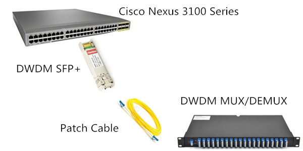
To build a complete DWDM network in your system, except for switches and DWDM SFP+ transceivers, you also usually need a DWDM mux/demux module. At present, DWDM mux/demux modules are available in 2 channels to 96 channels. Since Cisco DWDM SFP+ transceivers are available in 40 channels (from C20 1561.41nm to C59 1530.33nm ), now I will take 40 channels C20-C59 DWDM mux/demux module (show in the figure below) for example to explain how it works.

40 channels DWDM mux demux

Front panel of above 40 channels C20-C59 DWDM mux/demux module are shown in the figure below. Connectors, located on the front of the DWDM mux/demux modules, are labeled and use the same channel that is used to indicate the wavelength of the individual DWDM transceivers.

DWDM muxdemux
Use a pair of 40 channels C20-C59 DWDM mux/demux modules, 40 signals can be transmitted over one fiber pair, which greatly reduces the cabling cost.

40 DWDM muxdemux
Now, let’s use Cisco compatible DWDM SFP+ to connect DWDM transport to your Cisco 10G SFP+ switches!

Cisco Compatible DWDM SFP+

CWDM Mux/Demux User Guide

Share

When we demand for higher bandwidth, we often choose to install new fiber. However, that is an expensive solution. Then what should we do? Now this article will give you a less expensive solution—using CWDM Mux/Demux with CWDM transceivers, which may allow you to maximize capacity and increase bandwidth on existing fiber route by multiplexing several distinct signals or protocols over a single or duplex-fiber connection. The passive optical CWDM Mux/Demux usually utilizes a thin-film filter and circulator technology. They are available in various wavelength combinations based on the entire wavelength spectrum (1270nm–1610nm in 20nm increments) defined by the ITU G.694.2 CWDM standard. Accordingly, CWDM transceivers are also available in 1270nm–1610nm (20nm spacing).

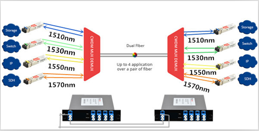
Since CWDM Mux/Demux can support 18 wavelengths include 1270, 1290, 1310, 1330, 1350, 1370, 1390, 1410, 1430, 1450, 1470, 1490, 1510, 1530, 1550, 1570, 1590 and 1610 nano-meters. Therefore, in the market, the channels of CWDM Mux/Demux varies from 2 channels to 18 channels. In this article, we may introduce these 4 channels CWDM Mux/Demux in detail. Using methods of other channel CWDM Mux/Demux can all reference 4 channels CWDM Mux/Demux.4 channels CWDM Mux/Demux is available in any four wavelengths from 1270nm–1610nm (20nm spacing). At present, CWDM Mux/Demux is available in dual fiber and single fiber two types. In the following passages, I will take 4 channels 1510-1570nm dual fiber CWDM Mux/Demux and 4 channels 1470-1590nm single fiber CWDM Mux/Demux for example to tell you how to use them in your WDM network.

4 Channels 1510-1570nm Dual Fiber CWDM Mux/Demux User Guide
To install a  4 channels 1510-1570nm dual fiber CWDM Mux/Demux in your network, you need a pairs of  4 channels 1510-1570nm dual fiber CWDM Mux/Demux. For dual fiber link  CWDM Mux/Demux, the Mux/Demux are always the same (shown in the following picture).

CWDM Mux/Demux User Guide

Just shown as the following picture. To install a  4 channels 1510-1570nm dual fiber CWDM Mux/Demux in your network, you just need a pair of 4 channels 1510-1570nm dual fiber CWDM Mux/Demux, a 1510nm SFP, 1530nm SFP1550nm SFP and a 1570nm SFP.

4 Channels 1510-1570nm Dual Fiber CWDM MuxDemux

4 Channels 1470-1590nm Single Fiber CWDM Mux/Demux User Guide
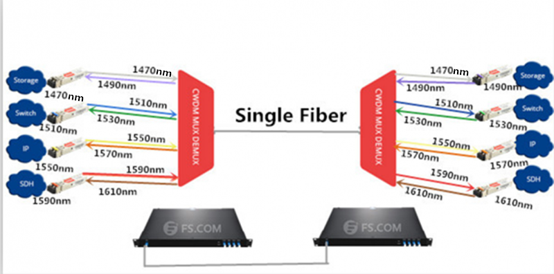
To install a  4 channels 1470-1590nm single fiber CWDM Mux/Demux in your network, you also need a pairs of  4 channels single fiber CWDM Mux/Demux. But for single fiber Mux/Demux, they are not the same. If you install a  4 channels 1470-1590nm single fiber CWDM Mux/Demux on one end, you may need to install a 4 channels 1490-1610nm single fiber CWDM Mux/Demux on the other end (shown in the following picture).

CWDM Mux/Demux User Guide

Just shown as the following picture. To install a  4 channels 1470-1590nm single fiber CWDM Mux/Demux in your network, you need a 4 channels 1470-1590nm single fiber CWDM Mux/Demux and 4 channels 1490-1610nm single fiber CWDM Mux/Demux pair. And a 1470nm SFP, 1510nm SFP, 1550nm SFP and 1590nm SFP for 4 channels 1470-1590nm single fiber CWDM Mux/Demux. A 1490nm SFP, 1530nm SFP, 1570nm SFP, 1610nm SFP for  4 channels 1490-1610nm single fiber CWDM Mux/Demux.

Single-Fiber CWDM Mux Demux Application