Tag Archives: FTTH

The Era of Fusion Splicing Is Coming

Share

Fusion splicingAs fiber deployment has become mainstream, splicing has naturally crossed from the outside plant (OSP) world into the enterprise and even the data center environment. Fusion splicing involves the use of localized heat to melt together or fuse the ends of two optical fibers. The preparation process involves removing the protective coating from each fiber, precise cleaving, and inspection of the fiber end-faces. Fusion splicing has been around for several decades, and it’s a trusted method for permanently fusing together the ends of two optical fibers to realize a specific length or to repair a broken fiber link. However, due to the high costs of fusion splicers, it has not been actively used by many people. But these years some improvements in optical technology have been changing this status. Besides, the continued demand for increased bandwidth also spread the application of fusion splicing.

New Price of Fusion Splicers
Fusion splicers costs have been one of the biggest obstacles to a broad adoption of fusion splicing. In recent years, significant decreases in splicer prices has accelerated the popularity of fusion splicing. Today’s fusion splicers range in cost from $7,000 to $40,000. The highest-priced units are designed for specialty optical fibers, such as polarization-maintaining fibers used in the production of high-end non-electrical sensors. The lower-end fusion splicers, in the $7,000 to $10,000 range, are primarily single-fiber fixed V-groove type devices. The popular core alignment splicers range between $17,000 and $19,000, well below the $30,000 price of 20 years ago. The prices have dropped dramatically due to more efficient manufacturing, and volume is up because fiber is no longer a voodoo science and more people are working in that arena. Recently, more and more fiber being deployed closer to the customer premise with higher splice-loss budgets, which results in a greater participation of customers who are purchasing lower-end splicers to accomplish their jobs.

More Cost-effective Cable Solutions
The first and primary use of splicing in the telecommunications industry is to link fibers together in underground or aerial outside-plant fiber installations. It used to be very common to do fusion splicing at the building entrance to transition from outdoor-rated to indoor-rated cable, because the NEC (National Electrical Code) specifies that outdoor-rated cable can only come 50 feet into a building due to its flame rating. The advent of plenum-rated indoor/outdoor cable has driven that transition splicing to a minimum. But that’s not to say that fusion splicing in the premise isn’t going on.

Longer distances in the outside plant could mean that sticking with standard outdoor-rated cable and fusion splicing at the building entrance could be the more economical choice. If it’s a short run between building A and B, it makes sense to use newer indoor/outdoor cable and come right into the crossconnect. However, because indoor/outdoor cables are generally more expensive, if it’s a longer run with lower fiber counts between buildings, it could ultimately be cheaper to buy outdoor-rated cable and fusion splice to transition to indoor-rated cable, even with the additional cost of splice materials and housing.

As fiber to the home (FTTH) applications continue to grow around the globe, it is another situation that may call for fusion splicing. If you want to achieve longer distance in a FTTH application, you have to either fusion splice or do an interconnect. However, an interconnect can introduce 0.75dB of loss while the fusion splice is typically less than 0.02dB. Therefore, the easiest way to minimize the amount of loss on a FTTH circuit is to bring the individual fibers from each workstation back to the closet and then splice to a higher-fiber-count cable. This approach also enables centralizing electronics for more efficient port utilization. In FTTH applications, fusion splicing is now being used to install connectors for customer drop cables using new splice-on connector technology and drop cable fusion splicer.

FTTH drop cable fusion splicer

A Popular Option for Data Centers
A significant increase in the number of applications supported by data centers has resulted in more cables and connections than ever, making available space a foremost concern. As a result, higher-density solutions like MTP/MPO connectors and multi-fiber cables that take up less pathway space than running individual duplex cables become more popular.

Since few manufacturers offer field-installable MTP/MPO connectors, many data center managers are selecting either multi-fiber trunk cables with MTP/MPOs factory-terminated on each end, or fusion splicing to pre-terminated MTP/MPO or multi-fiber LC pigtails. When you select trunk cables with connectors on each end, data center managers often specify lengths a little bit longer because they can’t always predict exact distances between equipment and they don’t want to be short. However, they then have to deal with excess slack. When there are thousands of connections, that slack can create a lot of congestion and limit proper air flow and cooling. One alternative is to purchase a multi-fiber pigtail and then splice to a multi-fiber cable.

Inside the data center and in the enterprise LAN, 12-fiber MPO connectors provide a convenient method to support higher 40G and 100G bandwidth. Instead of fusing one fiber at a time, another type of fusion splicing which is called ribbon/mass fusion splicing is used. Ribbon/mass fusion splicing can fuse up to all 12 fibers in one ribbon at once, which offers the opportunity to significantly reduce termination labor by up to 75% with only a modest increase in tooling cost. Many of today’s cables with high fiber count involve subunits of 12 fibers each that can be quickly ribbonized. Splicing those fibers individually is very time consuming, however, ribbon/mass fusion splicers splice entire ribbons simultaneously. Ribbon/mass fusion splicer technology has been around for decades and now is available in handheld models.

Ribbon/Mass Fusion Splicer

Conclusion
Fusion splicing provides permanent low-loss connections that are performed quickly and easily, which are definite advantages over competing technologies. In addition, current fusion splicers are designed to provide enhanced features and high-quality performance, and be very affordable at the same time. Fiberstore provides various types and uses of fusion splicers with high quality and low price. For more information, please feel free to contact us at sales@fs.com.

The Latest Generation of PON – NG-PON2

Share

To meet the large demand for high capacity transmission in optical access systems, 10G-PON (10G Passive Optical Network) has already been standardized by IEEE (Institute of Electrical and Electronics Engineers) and ITU (International Telecommunication Union). To enable the development of future optical access systems, the most recent version of PON known as NG-PON2 (Next-Generation Passive Optical Network 2) was approved recently, which provides a total throughput of 40 Gbps downstream and 10 Gbps upstream over a single fiber distributed to connected premises. The migration from GPON to 10G-PON and NG-PON2 is the maturity of technology and the need for higher bandwidth. This article will introduce the NG-PON2 technology to you.

GPON 10G-PON NG-PON2

What Is NG-PON2?
NG-PON2 is a 2015 telecommunications network standard for PON which was developed by ITU. NG-PON2 offers a fiber capacity of 40 Gbps by exploiting multiple wavelengths at dense wavelength division multiplexing (DWDM) channel spacing and tunable transceiver technology in the subscriber terminals (ONUs). Wavelength allocations include 1524 nm to 1544 nm in the upstream direction and 1596 nm to 1602 nm in the downstream direction. NG-PON2 was designed to coexist with previous architectures to ease deployment into existing optical distribution networks. Wavelengths were specifically chosen to avoid interference with GPON, 10G-PON, RF Video, and OTDR measurements, and thus NG-PON2 provides spectral flexibility to occupy reserved wavelengths in deployments devoid of legacy architectures.

How Does NG-PON2 Work?
If 24 premises are connected to a PON and the available throughput is equally shared then for GPON each connection receives 100 Mbps downstream and 40 Mbps upstream over a maximum of 20 km of fiber. For 10G-PON, which was the second PON revision, each of the 24 connections would receive about 400 Mbps downstream and 100 Mbps upstream. The recently approved NG-PON2 will provide a total throughput of 40 Gbps downstream and 10 Gbps upstream over a maximum of 40 km of fiber so each of the 24 connections would receive about 1.6 Gbps downstream and 410 Mbps upstream. NG-PON2 provides a greater range of connection speed options including 10/2.5 Gbps, 10/10 Gbps and 2.5/2.5 Gbps. NG-PON2 also includes backwards compatibility with GPON and 10G-PON to ensure that customers can upgrade when they’re ready.

NG-PON2 Work Principle

NG-PON2 Advantages
The NG-PON2 technology is expected to be about 60 to 80 percent cheaper to operate than a copper based access network and provides a clear undeniable performance, capacity and price advantage over any of the copper based access networks such as Fiber to the Node (FTTN) or Hybrid Fiber Coax (HFC). At present, three clear benefits of NG-PON2 have been proved. They are a 30 to 40 percent reduction in equipment and operating costs, improved connection speeds and symmetrical upstream and downstream capacity.

Reduced Costs
NG-PON2 can coexist with existing GPON and 10G-PON systems and is able to use existing PON-capable outside plant. Since the cost of PON FTTH (Fiber to the Home) roll out is 70 percent accounted for by the optical distribution network (ODN), this is significant. Operators have a clear upgrade path from where they are now, until well into the future.

Improved Connection Speeds
Initially NG-PON2 will provide a minimum of 40 Gbps downstream capacity, produced by four 10 Gbps signals on different wavelengths in the O-band multiplexed together in the central office with a 10 Gbps total upstream capacity. This capability can be doubled to provide 80 Gbps downstream and 20 Gbps upstream in the “extended” NG-PON2.

Symmetrical Upstream and Downstream Capacity
Both the basic and extended implementations are designed to appeal to domestic consumers where gigabit downstream speeds may be needed but more modest upstream needs prevail. For business users with data mirroring and similar requirements, a symmetric implementation will be provided giving 40/40 and 80/80 Gbps capacity respectively.

With the introduction of NG-PON2, there is now an obvious difference between optical access network and copper access network capabilities. Investment in NG-PON2 provides a far cheaper network to operate, significantly faster downstream and upstream speeds and a future-proof upgrade path all of which copper access networks do not provide, thus making them obsolete technologies. Telephone companies around the world have been carrying out trials of NG-PON2 and key telecommunication vendors have rushed NG-PON2 products to market.

Source: http://www.fs.com/blog/the-latest-generation-of-pon-ng-pon2.html

From O to L: the Evolution of Optical Wavelength Bands

Share

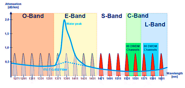
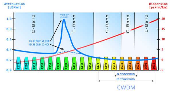
In optical fiber communications system, several transmission bands have been defined and standardized, from the original O-band to the U/XL-band. The E- and U/XL-bands have typically been avoided because they have high transmission loss regions. The E-band represents the water peak region, while the U/XL-band resides at the very end of the transmission window for silica glass.

Optical Wavelength Bands

Intercity and metro ring fiber already carry signals on multiple wavelengths to increase bandwidth. Fibers entering the home will soon do the same. Now there are several types of optical telecom systems have been developed, some based on time division multiplexing (TDM) and others on wavelength division multiplexing (WDM), either dense wavelength division multiplexing (DWDM) or coarse wavelength division multiplexing (CWDM). This article may represent the evolution of optical wavelength bands mainly by describing these three high-performance systems.

Dense Wavelength Division Multiplexing
DWDM systems were developed to deal with the rising bandwidth needs of backbone optical networks. The narrow spacing (usually 0.2 nm) between wavelength bands increases the number of wavelengths and enables data rates of several Terabits per second (Tbps) in a single fiber.

These systems were first developed for laser-light wavelengths in the C-band, and later in the L-band, leveraging the wavelengths with the lowest attenuation rates in glass fiber as well as the possibility of optical amplification. Erbium-doped fiber amplifiers (EDFAs, which work at these wavelengths) are a key enabling technology for these systems. Because WDM systems use many wavelengths at the same time, which may lead to much attenuation. Therefore optical amplification technology is introduced. Raman amplification and erbium-doped fiber amplifiers are two common types used in WDM system.

DWDM

In order to meet the demand for “unlimited bandwidth,” it was believed that DWDM would have to be extended to more bands. In the future, however, the L-band will also prove to be useful. Because EDFAs are less efficient in the L-band, the use of Raman amplification technology will be re-addressed, with related pumping wavelengths close to 1485 nm.

Coarse Wave Division Multiplexing
CWDM is the low-cost version of WDM. Generally these systems are not amplified and therefore have limited range. They typically use less expensive light sources that are not temperaturestabilized. Larger gaps between wavelengths are necessary, usually 20 nm. Of course, this reduces the number of wavelengths that can be used and thus also reduces the total available bandwidth.

CWDM

Current systems use the S-, C- and L-bands because these bands inhabit the natural region for low optical losses in glass fiber. Although extension into the O and E-band (1310 nm to 1450 nm) is possible, system reach (the distance the light can travel in fiber and still provide good signal without amplification) will suffer as a result of losses incurred by use of the 1310 nm region in modern fibers.

Time Division Multiplexing
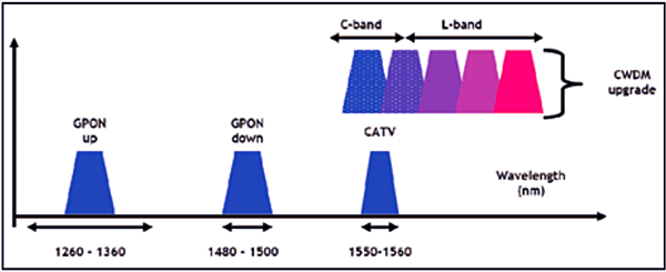
TDM systems use either one wavelength band or two (with one wavelength band allocated to each direction). TDM solutions are currently in the spotlight with the deployment of fiber-to-the-home (FTTH) technologies. Both EPON and GPON are TDM systems. The standard bandwidth allocation for GPON requires between 1260 and 1360 nm upstream, 1440 to 1500 nm downstream, and 1550 to 1560 nm for cable-TV video.

To meet the rise in bandwidth demand, these systems will require upgrading. Some predict that TDM and CWDM (or even DWDM) will have to coexist in the same installed network fibers. To achieve this, work is underway within the standardization bodies to define filters that block non-GPON wavelengths to currently installed customers. This will require the CWDM portion to use wavelength bands far away from those reserved for GPON. Consequently, they will have to use the L-band or the C- and L-bands and provided video is not used.

tdm

Conclusion
In each case, sufficient performance has been demonstrated to ensure high performance for today’s and tomorrow’s systems. From this article, we know that the original O-band hasn’t satisfied the rapid development of high bandwidth anymore. And the evolution of optical wavelength bands just means more and more bands will be called for. In the future, with the growth of FTTH applications, there is no doubt that C- and L-bands will play more and more important roles in optical transmission system. Fiberstore offer all kinds of products for WDM optical network, such as CWDM/DWDM MUX DEMUX and EDFA. For more information, please visit www.fs.com.

The Introduction of Optical Power Meter

Share

What Is an Optical Power Meter?
optical power meterAn Optical Power Meter usually knows as Fiber optical power meter is a device that used to measure the absolute optical signal and relate fiber optic loss. The term usually refers to a device for testing average power in fiber optic systems. Fiber optical power meter is a tool for telecommunication and CATV network. Optical power meter consists of a calibrated sensor, measuring amplifier and display. The sensor primarily consists of a photodiode selected for the appropriate range of wavelengths and power levels. On the display unit, the measured optical power and set the wavelength are displayed. Power meters are calibrated using a traceable calibration standard such as a NIST standard.

When to Use Optical Power Meter?
When you install and terminate fiber optic cables, you need to test them. A test should be conducted for each fiber optic cable plant for three main areas: continuity, loss, and power. In order to do this, you’ll need a fiber optic power meter.

How to Use Optical Power Meter?
When you measure fiber optic power with a power meter, you should attach the meter to the cable. Turn on the source of power, and view the meter’s measurement. Compare the meter measurement with the specified correct power for that particular system to make sure it have proper power not too much or too little . Correct power measurement is so important to fiber optic cables because the system works similar to electric circuit voltage, and the power must be just the right amount to work properly.

Classification of Optical Power Meter
There are two types of Optical Power Meter: Ordinary Optical Power Meter and PON Optical Power Meter. Ordinary optical power meter measures the optical power in the fiber link, typically an absolute power value 850/1300/1310/1490/1550/1625nm optical wavelength. While PON Optical Power Meter is more suitable for measuring the fiber to the home (FTTH) networks. Specific measurement: PON Optical Power Meter can send three wavelengths from a single laser output port (1310 nm, 1490 nm, 1550 nm), of which 1310nm can measure upstream transmission direction, 1490 nm and 1550 nm measure downstream direction. Upstream associated with your upload data, downward is download data.

Tips for Selection and Operation

  • Choose the best probe type and interface type.
  • Evaluation of calibration accuracy and manufacturing calibration procedures, and your fiber and connectors to match the required range.
  • Make sure the type and the range of your measurement and display resolution is consistent.
  • With immediate effect db insertion loss measurements.
  • Wear eye protection when working with high-power cables. Even with low-power layouts, it’s wise to check the connectors with your power meter before looking.

Ultra-High-Power Optical Amplifier for FTTH – EYDFA

Share

Background

While the Cable Modem, xDSL, and other forms of broadband access are booming in recent years, Fiber To The Home (FTTH) access is also gradually becoming a project that people are very interested in. The FTTH will eventually realize the “three networks in one” of Telephone, CATV and Internet, when the speed of data transmission can be more than 100 Mbps (200 times faster than the commonly used dial-up Internet access) and bring homes high-definition TV movies and fast online office, etc. FTTH can also solve the problem such as the quality of phone calls, the definition of television and so on.

From the perspective of the world’s situation, the FTTH’s promotion of South Korea and Japan has entered a rapid growth period; North America and Europe has begun to start which brings an optimistic outlook; China, Russia, India and South America is following and speeding up the development. From the perspective of FTTH, the optical communications industry market’s growth potential is still very large.

Applications of High-Power Optical Amplifiers

High-power optical amplifier as one of the basic devices of modern optical communications, is not only the premise of the existence of large-capacity and long-distance all-optical communication networks, but also plays a more and more important role in the process of fiber optic networks’ constantly extending and expanding. At present, in the central office, it usually needs to install more than one optical amplifiers in order to cover larger scope and more users. To take CATV for example, if a medium-sized county needs to send high-quality first-level TV signals to the villages and towns, it generally needs 4 to 8 sets of optical amplifiers. However, if high-power optical amplifiers are used, then only one is enough, which can greatly reduce the cost.

Solutions of High-Power Optical Amplifiers

Traditional Solution using EDFA Technology

One of the solutions for high-power optical amplifiers is to use the traditional general EDFA technology. As shown in the figure below, the signal is amplified at the first stage and then divided into several parts into several EDFAs at the second stage to realize the further ascension of power. The power enlarged in the end can be allocated.

Traditional High-Power Solution using EDFAs

Theare are mainly four problems of this solution:

  • The adoption of multilevel structure will make the optical structure very complex, and due to the adoption of multiple lasers in the internal part, the corresponding control scheme is very complicated.
  • As the multilevel structure has a WDM between the two stages of optical amplifiers, equivalent to bring more insertion loss to the optical path, the noise figure of EDFA amplifiers will deteriorate.
  • In addition, the traditional EDFAs use single mode fiber core pump technology, but high-power single-mode pumped lasers have been greatly restricted on technical and cost.
  • The whole sets of EDFA’s cost is very high and is very expensive.

Better Solution using EYDFA Technology

This ultra-high-power amplifier technology is a multimode cladding pump technology—EYDFA technology, a recently developed new technology that uses the Yb3+ and Er3+ ions doped double-clad fiber. The technology results to the combination of a series of new technologies, new processes and new materials. It is the core technology of ultra-high-power amplifiers and represents the development direction of optical amplifier technologies. While traditional EDFA use single-mode fiber core pump technology to achieve higher output power (which has been greatly limited on the technical and cost), the Er/Yb-Doped Fiber Amplifier (EYDFA) multimode cladding pump technology is the best choice for large output power optical amplifiers. Here is a typical optical structure of EYDFA.

EYDFA Structure

The main advantages of EYDFA are as following:

  • Compared with the single mode fiber core pump technology, multimode cladding pump technology has obvious advantages. The multimode cladding pump technology is to input the pump light to the multimode double-cladding fiber whose cross section are hundreds to thousands of times the single-mode fiber. As a result, at the same input optical density, multimode cladding pump can allow hundreds to thousands of times the single-mode pumped input, easily realizing the optical amplifiers’ high output power or ultra-high output power.
  • Can be realized using a simple optical structure, so the application form is very simple (as shown in the figure below).EYDFA Application Structure
  • The overall cost of the pumps can be greatly reduced.

Fiberstore’s high-power optical amplifier module type products—FTTH-EYDFA series are featured with high output power (17–26 dBm), low noise figure (less than 6 dB @ 1550 nm, 5 dBm input power), wide range of working wavelength (1540–1565 nm), flexible control, high reliability, etc. The output power of high-power optical amplifier is nearing 32 dBm in the laboratory.

Conclusion

Predictably, the widely applications of the ultra-high-power optical amplifiers (EYDFA) will have a profound impact on the development of optical communication, and its market prospect and effectiveness to economic and social present a good trend.

10G EPON Shipments Will Keep Growing

Share

FiberStore news, with the rapid global deployment of FTTH, PON global market scale is constantly expanding, but the current PON market growth is beginning to slow down. In the recent “2013 China Optical Network Seminar”, Ovum principal analyst Julie Kunstler, said in an interview, during 2011-2012, the global GPON / EPON OLT has begun to decline in shipments, the total revenue of PON equipment market is also declined.

However, although the growth of entire PON market started to slow down or even a decline, but 10G PON market has begun to be favored. Julie Kunstler said that, although it is not completely sure which sort of next generation PON technology will become the mainstream in the future, but in Ovum’s expectations, the shipments of 10G EPON OLT will maintain a growth trend.

As for the Chinese broadband access market, Julie Kunstler believes that, due to the different wiring conditions of each region and each district, the future Chinese FTTx market penetration is expected to reach 40% -50%, the future will be a variety of access technologies co-exist, including PON, ADSL, VDSL, etc.

Julie Kunstler pointed out that, 2012 was the first year GPON OLT shipments beyond that of EPON, but the OLT total market has already begun to decline. Data show that, in the first quarter of 2013, EPON OLT shipments decreased 7%, compared to the same period down 46%; GPON OLT shipments decreased by 9%, an increase of 28%. In revenues, in the first quarter of 2013, EPON revenue decreased 25%, down 46%; GPON revenues decreased 29 percent, an increase of 3%.

Ovum predicts that, in the next few years, global GPON / EPON OLT shipments will further decline, it will be expected to from 41 million in 2012 decline to 13 million in 2018. At the same time, in 2012 GPON / EPON ONT / ONU’s shipments increased 43 percent compared to 2011, 2012 EPON ONT / ONU shipments still ahead of GPON ONT / ONU shipments, in 2013 GPON ONT/ONU shipments will just run after EPON.

Although entire PON market growth started to slow down or even a decline, but 10G PON market has begun to rise. Julie Kunstler said that, although what sort of future generation PON technology will become the mainstream is still not completely sure, but in Ovum’s expectations shipments of 10G EPON OLT will maintain a growth trend, and its application scenarios will be mainly reflected in FTTB, mobile backhaul, etc. Ovum forecasts, 10G EPON OLT’s shipments will maintain growth trend in 2018 will reach 500 thousand, 10G GPON OLT’s shipments will still be relatively small.

Google Fiber is Aiming to Breakout the U.S Telecommunication Duopoly Market

Share

Google Fiber is Aiming to Breakout the U.S Telecommunication Duopoly Market FiberStore News, According to the foreign media reports, since its inception, Google Fiber is basically regarded as an experiment in the industry, aiming to highlight the poor performance of the network service providers to promote high-speed broadband services, which is also test platform of next generation of advertising and video technology. Google has been working to correct this stereotypes of people, and repeatedly stressed that it is their serious business to carry out, even if there are indications that they would never in a nationwide promotion of Google Fiber (only a handful of cities deployment)

Media reports fully proved Google is by trying to get people to think more seriously about Google’s fiber optic network project to get it regarded as a major broadband company, although not always the case. Technology News clearly states: This network was initially seen as what the Internet giant used to test its news services and advertising model as an experiment network. Others also would like to know if Google network is just is a mean to promote the existing cable TV and phone companies to provide faster Internet service. Obviously, it was agreed that Google as a rich and powerful technology giant is affordable with this project and simply credited the cost as research and development expenditures.
The reason of Google fiber networks impress on peoples in this way is because that is the truth. This makes Google recently announced the entry into Austin and Prove does not really change that. Google Fiber is an amazing little experiment, although it may ultimately have a huge impact, it is till a long time for it to get rid of “the interesting experiment” (in issues on the U.S market capacity background and connectively)
It is not important that how we call it. Google Fiber MiloMeldin (formerly known as @Home) participate in the association meeting on FTTH in North America this week, and reiterated Google fiber network is a serious money-making initiatives. During the meeting, other than repeatedly requesting for subsidies, deregulation or complaining the poor service (just like the attitude of telecommunication industry’s mobile operators towards the large carries), Google in turns insisted that the earnings of working with the local government is rather abundance.
To be specifically, Google requires Kansas City as the assigned inspector for the Google Fiber project construction to enable speedy completion of the city’s periodic inspection, which will further saves the time and money that Google invest I the construction phase. This company also requires deploy fiber in other cities’ piping, and minimizing the unnecessary street excavation projects. The company has cooperated with the public utility companies to get the supported base station location for connections of the new fiber optic network.
Despite all these sound very good, but as of now, Google has not disclosed any convincing financial data, and Google Fiber has not yet been deployed on a large scale in families except a few part families. Although it is welcomed that Google Fiber intended to break the duopoly U.S telecommunication market, it is still a long way to go if it let people to see it as a real player in the market and a truly disruptive market forces.