Category Archives: Optical Amplifiers

5 Concepts Help Easily Get WDM System

Share

The Wavelength Division Multiplexing (WDM) system is a passive, optical solution for increasing the flexibility and capacity of existing fiber lines in high-speed networks. By adding more channels onto available fibers, the WDM System enables greater versatility for data communications in ring, point-to-point, and multi-point topologies for both enterprise and metro applications. Do you know about WDM system? 5 concepts provided in this blog may help you easily get it.

Optical Transmission
Optical transmission is the conversion of a digital stream of information to light pulses. The light pulses are generated by a laser source (LED or vessel) and transmitted over an optical fiber. The receiver converts the light pulses back to digital information.

Optical Transmission

Wavelength Division Multiplexing
WDM is based on the fact that optical fibers can carry more than one wavelength at the same time. The lasers are transmitting the light pulses at different wavelengths that are combined via filters to one single output fiber. The device used to combine wavelengths is called multiplexer and the device used to separate wavelengths is called demultiplexer, which are the two most basic component in WDM system.

Wavelength Division Multiplexing

Optical Amplifiers
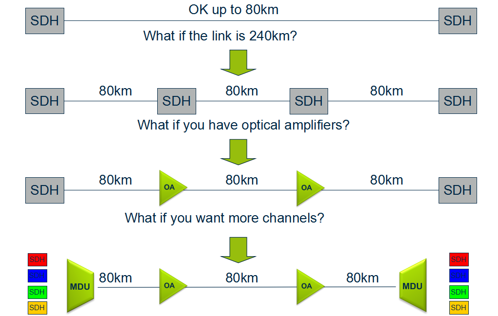
An optical amplifier is a device that amplifies an optical signal directly, without the need to first convert it to an electrical signal. Optical amplifiers boosts the attenuated wavelengths and are more cost efficient than electrical repeaters. Without amplifiers the reach is limited to 80-100km before electrical regeneration. Amplifier stations typically each 80-100km.

optical-amplifiers
Depending on signal types and fiber characteristics, amplifiers are used in DWDM networks and increases the reach of the optical signals up to 3000 km. Amplifiers are an basic building block for a powerful DWDM network.
Optical Amplifiers

Transponder
Transponders provides wavelength conversion from client to WDM signal. A transponder maps a single client to a single WDM wavelength. The digital framing of a line signal from a transponder provides service monitoring, management connectivity and increased reach. The broad range of available transponders enables cost efficient solutions for both CWDM & DWDM.
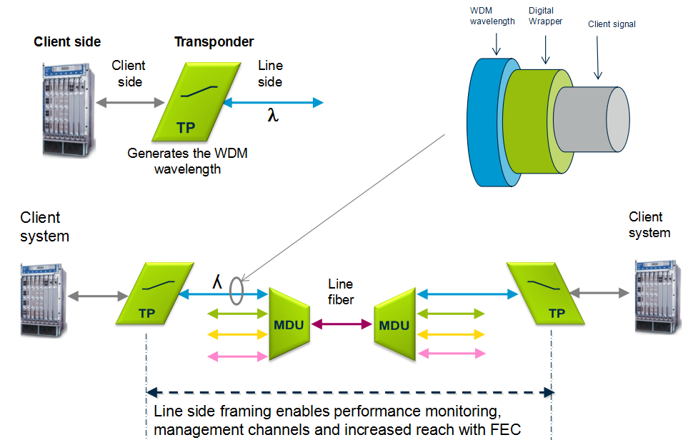
transponder

Optical Add Drop Multiplexer
The main function of an optical multiplexer is to couple two or more wavelengths into the same fiber. If a demultiplexer is placed and properly aligned back-to-back with a multiplexer, it is clear that in the area between them, two individual wavelengths exist. This presents an opportunity for an enhanced function, one in which individual wavelengths could be removed and also inserted. Such a function would be called an Optical Add Drop Multiplexer (OADM). OADM is used for increased flexibility in the optical paths. Services can be redirected upon failure or capacity constraints and capacity can be increased dynamically per node.
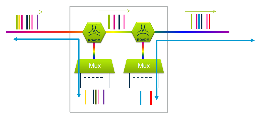
optical-add-drop-multiplexer

Conclusion
Multiplexer and demultiplexer are the most basic component in WDM system. If your transmission distance is more than 100 km, an optical amplifier is necessary. If your client wavelength isn’t available for WDM applications, you may need a transponder to convert it to WDM available wavelength. Want to achieve a more flexible, just choose to use a OADM. Besides these, sometimes, a dispersion compensation module is also needed to fix the form of optical signals that are deformed by chromatic dispersion and compensates for chromatic dispersion in fiber that causes the light pulses to spread and generate signal impairment. Do you get WDM system? Just start to build your own WDM system now!

Erbium Doped Fiber Amplifier (EDFA) Used in WDM System

Share

The capacity of fiber optical communication systems has undergone enormous growth during the last few years in response to huge capacity demand for data transmission. With the available wavelength division multiplexing (WDM) equipment, commercial system can transport more than 100 channels over a single fiber. However, increasing the number of channels in such systems will eventually result in the usage of optical signal demultiplexing components with greater values of optical attenuation. Besides, when transmitted over long distances, the optical signal is highly attenuated. Therefore, to restore the optical power budget, it is necessary to implement optical signal amplification. This article may mainly tell you  why EDFA is used in WDM system and how does it work.

Why Use EDFA in WDM System?

EDFA stands for erbium-doped fiber amplifiers, which is an optical amplifier that uses a doped optical fiber as a gain medium to amplify an optical signal. EDFA has large gain bandwidth, which is typically tens of nanometers and thus actually it is enough to amplify data channels with the highest data rates. A single EDFA may be used for simultaneously amplifying many data channels at different wavelengths within the gain region. Before such fiber amplifiers were available, there was no practical method for amplifying all channels between long fiber spans of a fiber-optic link. There are practically two wavelength widows C-Band (1530nm-1560nm) and L-Band (1560nm-1600nm). EDFA can amplify a wide wavelength range (1500nm-1600nm) simultaneously, which just satisfies the DWDM application, hence it is very useful in WDM for amplification.

How Does EDFA Work ?

The basic configuration for incorporating the EDFA in an optical fiber link is shown in the picture below. The signals and pump are combined through a WDM coupler and launched into an erbium-doped fiber (EDF). The amplified output signals can be transmitted through 60-100km before further amplification is required.

EDFA
Erbium-doped fiber is the core technology of EDFA, which is a conventional silica fiber doped with erbium ions as the gain medium. Erbium ions (Er3+) are having the optical fluorescent properties that are suitable for the optical amplification. When an optical signal such as 1550nm wavelength signal enters the EDFA from input, the signal is combined with a 980nm or 1480nm pump laser through a wavelength division multiplexer device. The input signal and pump laser signal pass through erbium-doped fiber. Here the 1550nm signal is amplified through interaction with doped erbium ions. This can be well understood by the energy level diagram of Er3+ ions given in the following figure.

EDFA

Where to Buy EDFA for Your WDM System ?

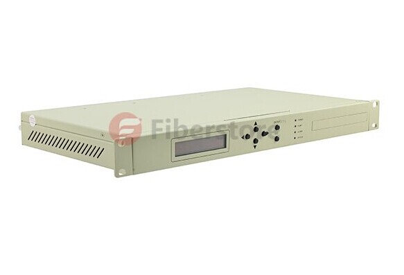
To ensure the required level of amplification over the frequency band used for transmission, it is highly important to choose the optimal configuration of the EDFAs. Before you buy a EDFA, keep in mind that the flatness and the level of the obtained amplification, and the amount of EDFA produced noise are highly dependent on each of the many parameters of the amplifier. Fiberstore provide many kinds of EDFAs, especially the DWDM EDFAs (shown in the picture below), which have many output options (12dBm-35dBm). Besides, they are very professional in optical amplifiers. Whatever doubts you have, they can give a clear reply.

EDFA

Ultra-High-Power Optical Amplifier for FTTH – EYDFA

Share

Background

While the Cable Modem, xDSL, and other forms of broadband access are booming in recent years, Fiber To The Home (FTTH) access is also gradually becoming a project that people are very interested in. The FTTH will eventually realize the “three networks in one” of Telephone, CATV and Internet, when the speed of data transmission can be more than 100 Mbps (200 times faster than the commonly used dial-up Internet access) and bring homes high-definition TV movies and fast online office, etc. FTTH can also solve the problem such as the quality of phone calls, the definition of television and so on.

From the perspective of the world’s situation, the FTTH’s promotion of South Korea and Japan has entered a rapid growth period; North America and Europe has begun to start which brings an optimistic outlook; China, Russia, India and South America is following and speeding up the development. From the perspective of FTTH, the optical communications industry market’s growth potential is still very large.

Applications of High-Power Optical Amplifiers

High-power optical amplifier as one of the basic devices of modern optical communications, is not only the premise of the existence of large-capacity and long-distance all-optical communication networks, but also plays a more and more important role in the process of fiber optic networks’ constantly extending and expanding. At present, in the central office, it usually needs to install more than one optical amplifiers in order to cover larger scope and more users. To take CATV for example, if a medium-sized county needs to send high-quality first-level TV signals to the villages and towns, it generally needs 4 to 8 sets of optical amplifiers. However, if high-power optical amplifiers are used, then only one is enough, which can greatly reduce the cost.

Solutions of High-Power Optical Amplifiers

Traditional Solution using EDFA Technology

One of the solutions for high-power optical amplifiers is to use the traditional general EDFA technology. As shown in the figure below, the signal is amplified at the first stage and then divided into several parts into several EDFAs at the second stage to realize the further ascension of power. The power enlarged in the end can be allocated.

Traditional High-Power Solution using EDFAs

Theare are mainly four problems of this solution:

  • The adoption of multilevel structure will make the optical structure very complex, and due to the adoption of multiple lasers in the internal part, the corresponding control scheme is very complicated.
  • As the multilevel structure has a WDM between the two stages of optical amplifiers, equivalent to bring more insertion loss to the optical path, the noise figure of EDFA amplifiers will deteriorate.
  • In addition, the traditional EDFAs use single mode fiber core pump technology, but high-power single-mode pumped lasers have been greatly restricted on technical and cost.
  • The whole sets of EDFA’s cost is very high and is very expensive.

Better Solution using EYDFA Technology

This ultra-high-power amplifier technology is a multimode cladding pump technology—EYDFA technology, a recently developed new technology that uses the Yb3+ and Er3+ ions doped double-clad fiber. The technology results to the combination of a series of new technologies, new processes and new materials. It is the core technology of ultra-high-power amplifiers and represents the development direction of optical amplifier technologies. While traditional EDFA use single-mode fiber core pump technology to achieve higher output power (which has been greatly limited on the technical and cost), the Er/Yb-Doped Fiber Amplifier (EYDFA) multimode cladding pump technology is the best choice for large output power optical amplifiers. Here is a typical optical structure of EYDFA.

EYDFA Structure

The main advantages of EYDFA are as following:

  • Compared with the single mode fiber core pump technology, multimode cladding pump technology has obvious advantages. The multimode cladding pump technology is to input the pump light to the multimode double-cladding fiber whose cross section are hundreds to thousands of times the single-mode fiber. As a result, at the same input optical density, multimode cladding pump can allow hundreds to thousands of times the single-mode pumped input, easily realizing the optical amplifiers’ high output power or ultra-high output power.
  • Can be realized using a simple optical structure, so the application form is very simple (as shown in the figure below).EYDFA Application Structure
  • The overall cost of the pumps can be greatly reduced.

Fiberstore’s high-power optical amplifier module type products—FTTH-EYDFA series are featured with high output power (17–26 dBm), low noise figure (less than 6 dB @ 1550 nm, 5 dBm input power), wide range of working wavelength (1540–1565 nm), flexible control, high reliability, etc. The output power of high-power optical amplifier is nearing 32 dBm in the laboratory.

Conclusion

Predictably, the widely applications of the ultra-high-power optical amplifiers (EYDFA) will have a profound impact on the development of optical communication, and its market prospect and effectiveness to economic and social present a good trend.

Some Developments that May Occur in the Fiber Amplifier

Share

This page will focus on fiber optic amplifiers?application, and obviously, the introduction of EDFA in a long distance network has been the first, application identified by several telecom’s operators. I just think EDFA’s advantage is that using the existing cable from 565 Mbit/s systems. Into a 2400 Mbit/s without any additional electronic requirement, maybe this is one of the cost/performance ratio advantage of the optical amplifier versus the conventional technologies. Other applications arise from those countries where the telecommunication network infrastructures are poor, or even non existing. In such a situation the possibility to reach a distance in the order of 200km at 140 or 565 Mbit/s makes the use of EDFA more competitive.

Optical amplification has been already successfully tested in various laboratories and field trials in Europe, North America and Japan. Worldwide standards authority is still working on the standardization of EDFA optical amplifier. Major telecom manufactures already supply line terminals with integrated optical amplifier functions. As far as the future submarine links are concerned, it is expected that in a few years, because of optical amplification, the electronical of today submerged repeaters, will be amended by replacing all optical amplifiers.

Well, an example of the power budget calculations at 2400 Mbit/s is given in the annex, where an EDFA system composed by a power amplifier and a pre-amplifier has been considered. In combination with a dispersion shifted submarine fiber optic cable, it belongs to outdoor fiber optic cable. Junction Networks. The massive introduction of SDH systems, and the forecast use of it on the existing cables, has made the use of EDFA technologies achievable also in the junction networks area. In Europe, North America and Japan, this possibility will be limited to the intercity applications.

In connection with the subscriber loop network design, a similar range of products is drawn up by the worldwide industry for the next generation of CATV systems. It is CATV amplifier. In a near future optical transmitters with Booster Amplifier? integrated in the same equipment, will need to be able to transmit up to 60/80 television channels simultaneously, in a cluster of 200/300 subscribers each. The figure showed a?Booster EDFA Optical Amplifier.

edfa

Although CATV amplifier housing employed in current CATV networks is designed to accommodate a return path amplifier, most of today’s CATV system have unactivated return channels. Roughly 20 percent of today’s CATV systems use some fiber optic links to bypass slow amplifier chains in the trunk portion of the network. Service is typically provided to residences and apartments, with relatively limited business locations connected to CATV networks. Similar applications product has WDM amplifier. In-line amplifier, just differ in the range of applications. There is usually only a single CATV operator in a given service area, with nascent competition from microwave and direct broadcast satellite service providers. Television receives only background antennas that are 1 to 2 meters in diameter are used by a small fraction of residential customers. With the fast developments of fiber optical amplifiers, I am very bullish on the trend of it, hope it can be dragged out more widely features and bring more benefits to people.

Related Article:  Which Patch Cable Should I Choose for My Optical Transceiver?

Some Knoweledge About Erbium-droped Fiber Amplifer

Share

The eribum-doped fiber amplifier (EDFA) was first reported in 1987, and, in the short period since then, its applications have transformed the optical communications industry. Before the advent of optical amplifers, optical transmission systems typically consisted of a digital transmitter and a receivere separated by spans of transmission optical fiber intersersed with optoelectronic regenerators. The optoelectronic regenerators corrected attenuation, dispersion, and other transmission degradations of the optical signal by detecting the attenuated and distorted data pulses, electronically reconstituting them, and then optically transmitting the regenerated data into the next transmission span.

The EDFA is an optical amplifer that faithfully amplifies lightwave signals purely in the optical domain. EDFAs have several potential functions in optical fiber transmission systems. They can be used as power amplifiers to boost transmitter power, as repeaters or in-line amplifiers to increase system reach, or as preamplifiers to enhance receiver sensitivity. The most far-reaching impact of EDFAs has resulted from their use as repeaters in place of conventional optoelectronic regenerators to compensate for transmission loss and extend the span between digital terminals. Used as a repeater, the optical amplifier offers the possibility of transforming the optical transmission line into a transparent optical pipeline that will support signals independent of their modulation format or their channel data rate. Additionally, optical amplifiers support the use of wavelenth division multiplexing (WDM), whereby signals of different wavelengths are combined and transmitted together on the same transmission fiber.

In fiber optic systems amplification of the signal is necessary because no fiber material is absolutely transparent. This causes the infrared light (usually around 1530nm) carried by a fiber to be attenuated as it travels through the material. Because of this attenuation, repeaters must be used in spans of optical fiber longer than approximately 100 kilometers.

The operating wavelength range of a standard EDFA spans over the entire so-called “C band” (1530 to 1560 nm) and therefore allows amplification of a variety of wavelength channels that are used in wave-length division multiplexing (WDM)applications. This is a major advantage over methods in which the optical signal is converted into an electrical signal, amplified and converted back to light. Due to the last step, such O/E-E/O regenerators require the demultiplexing and multiplexing of each single WDM channel at each regenerator site and an O/E-E/O pair for each channel.

EDFA Configurations

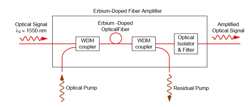
The configuration of a co-propagating EDFA is shown in Figure 5. The optical pump is combined with the optical signal into the erbium-doped fiber with a wavelength division multiplexer. A second multiplexer removes residual pump light from the fiber. An in-line optical filter provides additional insurance that pump light does not reach the output of the optical amplifiers. An optical isolator is used to prevent reflected light from other portions of the optical system from entering the amplifier.

fiber optic amplifer

Figure 5. An EDFA for which the optical signal and optical pump are co-propagating.

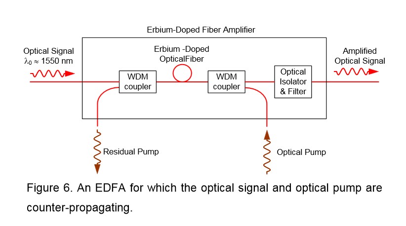
An EDFA with a counter propagating pump is pictured in Figure 6. The co-propagating geometry produces an amplifier with less noise and less output power. The counter propagating geometry produces a noisier amplifier with high output power. A compromise can be made by combining the co- and counter-propagating geometries in a bi-directional configuration.

EDFA Amplifer

The propagation and amplification properties of an erbium-doped fiber at 1550 nm are obtained. A simple EDFA is constructed, and its performance is tested. A small signal with wavelength of 1530 nm can be amplified with amplification up to 14 dB/m and SNR of 18.8, if a pumping laser of wavelength 980 nm and driving current 400 mA is used. A higher amplification is expected if a more intense pumping laser is supplied. The erbium doped fiber amplifier proves efficient and concise in amplifying signals around 1550 nm.

Erbium-Doped Fiber Amplifier for DWDM Systems

Share

DWDM EDFA (Erbium-Doped Fiber Amplifier) is a key component in DWDM network systems. It uses an optical supervisory channel power adjustment and extends the power link budget for long distance DWDM communication systems. As the operating bandwidth of the EDFA has 30nm, it can zoom back of a plurality of different wavelength optical signals, and so it can be very conveniently used in DWDM systems to compensate for various optical attenuation.
With gain flattening filter, DWDM EDFA offers constant flat gain for multi-channel DWDM systems. It works at C-band or L-band, integrates electric driver, remote control, temperature control, and alarm circuits all together in a small package. It has assembled up to three pump lasers to meet the different output power levels required by DWDM systems and protect the pump failure.

FiberStore provides 40 channel BA Module DWDM EDFA. This product is spectrum flat EDFA for DWDM system. It offers high optical gain, low noise figure and high saturation optical power which are fully integrated with various kinds of DWDM systems. This DWDM EDFA has perfect network interfaces including one Ethernet RJ45 port, one RS232 port and two RS485 ports. And the open mib ensure the connectivity with all other network management system. Click here for the DWDM EDFA price.


FiberStore DWDM EDFA Features

1. Low noise figure with typical 4.5dB and high flatness with typical 1dB

2. Covers whole C-band and carries 40 or 80 channels

3. Redundancy hot swap power module with 110/220V AC and 48V DC can plug mix

5. Supports telnet and SNMP network management

6. Gain can be adjustable by network and manual

7. High precise AGC (automatic gain control) and ATC (automatic temperature control) circuits
8. High saturation output power

9. Flexible mechanics and circuit structures (Module, 1U Rack and Gain Block)

10. OEM is available and fully compatible with Telecordia GR-1312-CORE

FiberStore DWDM EDFA Functions

1. A 5V OLT 25W ATT power supply with input protection and output filtering. It is necessary to monitor the current supplied to the EDFA (this gives a measure of the aging of the device) and desirable to monitor the voltage.

2. Drive two digital input lines which control the gain of the DWDM EDFA.

3. Monitor two analog outputs which measure the input and output optical amplifier power levels.

4. Communicate with the EDFA serial port which is RS232 protocol but at TTL levels. (This allows more detailed health monitoring and setting of operating conditions that is possible using only the digital signals.)

5. Communicate with a LMA monitor and control bus. The controller is a circuit card 40mm wide by 220mm high.

Technology Of Fiber Optic Amplifiers

Share

In fiber optic communication, the visible-light or infrared (IR) beams carried by a fiber are attenuated as they travel through the material. Then there comes to the fiber optic amplifier which is used to compensate for the wakening of information during the transmission.

Amplifiers are inserted at specific places to boost optical signals in a system where the signals are weak. This boost allows the signals to be successfully transmitted through the remaining cable length. In large networks, a long series of optical fiber amplifiers are placed in a sequence along the entire network link.

Common fiber optical amplifiers include Erbium-Doped Fiber Amplifier (or EDFA Amplifier), Raman fiber amplifier, and silicon optical amplifier (SOA). Erbium doped fiber amplifier is the major type of the fiber amplifier used to boost the signal in the WDM fiber optic system, as we know it is WDM that increase the capacity of the fiber communications system and it is the erbium-doped fiber amplifier that makes WDM transmission possible. Fiber amplifiers are developed to support Dense Wavelength Division Multiplexing (DWDM) which is called DWDM EDFA amplifier and to expand to the other wavelength bands supported by fiber optics.

There are several different physical mechanisms that can be used to amplify a light signal, which correspond to the major types of optical amplifiers. In doped fibre amplifiers and bulk lasers, stimulated emission in the amplifier’s gain medium causes amplification of incoming light. In semiconductor optical amplifiers (SOAs), electron-hole recombination occurs. In Raman amplifiers, Raman scattering of incoming light with phonons in the lattice of the gain medium produces photons coherent with the incoming photons. Parametric amplifiers use parametric amplification.

When light is transmitted through matter, part of the light is scattered in random directions. A small part of the scattered light has frequencies removed from the frequency of the incident beam by quantities equal to the vibration frequencies of the material scattering system. Raman fiber optic amplifiers function within this small scattering range. If the initial beam is sufficiently intense and monochromatic, a threshold can be reached beyond which light at the Raman frequencies is amplified, builds up strongly, and generally exhibits the characteristics of stimulated emission. This is called the stimulated or coherent Raman effect.

EFDA fiber optic amplifier functions by adding erbium, rare earth ions, to the fiber core material as a dopant; typically in levels of a few hundred parts per million. The fiber is highly transparent at the erbium lasing wavelength of two to nine microns. When pumped by a laser diode, optical gain is created, and amplification occurs.

Silicon or semiconductor optical amplifier functions in a similar way to a basic laser. The structure is much the same, with two specially designed slabs of semiconductor material on top of each other, with another material in between them forming the “active layer”. An electrical current is set running through the device in order to excite electrons which can then fall back to the non-excited ground state and give out photons. Incoming optical signal stimulates emission of light at its own wavelength.

Fiber optic repeater also can re-amplify an attenuated signal but it can only function on a specific wavelength and is not suitable for WDM systems. That is the reason why optical fiber amplifier plays a much more important role in communication systems.

The Chanllenges of Technology And Cost 100G Faced

Share

More and more high bandwidth services such as high definition(HD) video, online games and video conference challenging the traditional network, 100G as a ease network bandwidth technology, becomes the new hope of the operator.

100G industry chain has matured, with all components and subsystems have commercial capacity of multiple manufacturers, the market also needs the support of 100G system, the backbone network will be fully transferred to the 100G-leading era. From the early 2013, the focus point of 100G is from the laboratory into 100G network deployment and the commercial 100G has started.

Four Technical Challenges Of 100G

Although the 100G has been carried out, but the 100G transmission technology meets four technical challenges.

First, high power consumption. The achievement mechanism of 100G technology is complex, the optical receiver requires the use of coherent reception and processing of the DSP, the key chip has no ASIC, resulting in high power consumption of the whole 100G system. When large-scale commercial 100G technology, the average power consumption of each wavelength is still a problem waiting to be solved. Currently the power consumption of per wavelength is above 200W, the average power consumption of per frame is 7000W, so there will need three frames. Obviously, the 28nm process can help to reduce energy consumption, but there is no 100G solution of 28-nanometer. In addition, although the light energy consumption is not large, but due to the use of next-generation optical transceiver will increase greatly, reducing the power consumption is very necessary.

The second is integrated, especially in the field of optical circuit and photoelectric integration. How to add mass active and passive optical devices such as laser, optical amplifier, wavelength division multiplexing(WDM) and transmitter/receiver to the network to achieve highly integrated? Using semiconductor technology to the integration of CWDM and laser?

The third is test. The challenges of 100G testing include the quality evaluation of the deployed 100G system signal and the system maintenance after deployed. 100G using polarization multiplexing, and the signal spectrum is wide, the common OSDR and test instruments can not real-time test it, only by shutting off the laser method. How to achieve real-time test is industry’s future research topic, many of today’s online testing system are worth studying.

The Fourth is few prospective studies. How to make the current transmission system gradually shift to user-oriented management from the traditional network management? Quickly and efficiently allocate the physical resources?

The key is the problem of cost

The key reason why 100G failed to be applied large-scale currently is the opportunity cost is relatively too high. In the era of 100G, the cost of optical module is very high. The mainstream CFP module, the actual sales price is more than $10,000. From the point of optical module cost, 100G module is several times higher than 10G optical module. It also requires manufacturers continue to make efforts in chip integration, integrated optical module miniaturization and system design, to achieve the overall cost of products are reduced.

Especially the regard of optical module technology, the cost of this part is the key of the whole 100G system cost, the optical module itself has to face the challenges of control power consumption and improve board integration.

Overview Optical Fiber Amplifier From Fiberstore

Share

The Optical Amplifiers are devices that direct the amplified light signal, without the need to first convert it into an electrical signal. Prior to this, the transmission signal amplification to achieve the photoelectric conversion and electro-optical conversion, i.e., O / E / O converting. With the optical amplifier can achieve optical signal amplification. The successful development of the optical amplifier and its industrialization is a very important achievement in the optical fiber communication technology, it has greatly contributed to the development of optical multiplexing, optical soliton communication and all-optical network.

Fiber amplifier will not only directly amplifying optical signals, and also offers real-time, high gain, broadband, online, low noise, low loss optical zoom function is the key components of a new generation of optical fiber communication systems essential. The Fiber Amplifier Usually by the gain medium, the pumping light input-output coupling structure and composition. Fiber amplifier mainly erbium-doped fiber amplifier, semiconductor optical amplifiers and three optical fiber Raman amplifier according to the position and the role of the fiber amplifier in the optical fiber line relay amplification, generally divided into three pre-amplification and power amplification.

Optical Fiber Amplifier(OFA) is used in optical fiber communication lines, to achieve a new all-optical signal amplification amplifier. Erbium-doped fiber amplifier (EDFA), semiconductor optical amplifier (SOA) and optical fiber Raman amplifier (FRA), erbium-doped fiber amplifier with its superior performance in practical fiber amplifier is now widely used in long distance, high-capacity, high-speed optical fiber communication systems, access networks, optical fiber CATV networks, military systems (radar multi-channel data multiplexing, data transmission, guidance, etc.) in areas such as power amplifiers, repeaters amplifier and preamplifier .

Coexistence of CATV network for hybrid fiber / coax structure of a variety of systems, the erbium-doped fiber amplifier is increasingly able to get attention, especially the front-end centralized system, point-to-multipoint light wave structure and long-distance trunk transmission system especially. For CATV designers most commonly tree distribution network, the efficiency of the system is determined by the cost per user. CATV amplifier is a electronic device that accept a varying input signal and produce an output signal that varies in the same way as the input, but has larger amplitude.Therefore, the use of erbium-doped fiber amplifier to increase the optical power on the basis of the original transmitting equipment, services for more users, thereby reducing the cost of the transmitter units of milliwatts. In addition, in recent years, including erbium-doped fiber amplifier 1550nm light emitting device can be the cheapest fiber to the curb and fiber to the building. All in all, CATV fiber trunk transmission and power distribution system as well as the progressive realization of the “triple play” of voice, video, data path transmission for the ultimate realization of broadband integrated services digital network, erbium-doped fiber amplifier will play an invaluable role.

For more Optical Amplifiers information,please visit fs.com or via Sales@fs.com to contact us.Fiberstore is profession supplier and manufacturer of optical amplifiers.You can save cost to buy fiber optic products by fiberstore.