Tag Archives: cable management

Server Rack Cable Management: What Is the Best Practice?

Share

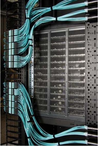
Data centers today consist of rows of server racks and network cabinets to support an abundance of data cables, power cords and network devices. Deliver proficient cable management within a confined and tightly-spaced server rack is quite difficult. However, cable management is no longer a nightmare if you follow the right guide and work with some test-and-tried tools. Here we’d like to offer useful advice for server rack cable management, and recommend some efficient and reliable management tools.

server rack cable management

Server Rack Cable Management Benefits

Server rack cable management, if not being handled properly, could bring you a succession of problems – it would result in cable damage and failure, which directly lead to data transmission errors, performance issues and system downtime. On the contrary, successful cable management in server rack can benefit you in every aspects, including:

Improved system performance: server rack cable management demands to separate power and data cables within the racks, which greatly decrease the chance for crosstalk and interference.

Enhanced availability: Effective server rack cable management allows easier access to cables and IT devices, yet to reduce human error.

Improved maintenance and serviceability: Effective rack cable management also ensures easier and safer access to individual components.

Increased cooling efficiency: let hot exhaust air out from the back, server rack cable management keeps cables organized and out of critical airflow paths.

Improved scalability: cable management in server rack simplifies moves, adds, and changes, making it easier to integrate additional racks and components for future growth.

Server Rack Cable Management Guide

Since we’ve made clear the benefits of server rack cable management, here is a step-to-step guide for you to further explain how to do it correctly:

  • Plan appropriately. It greatly contributes to smooth server rack management process. Consulting a professional cabling contractor can always be beneficial.
  • Determine the routes for power and data cables. Determine if they enter from the top or bottom of the server rack. Then plan the routes to separate power and data cables, and copper data cables and fiber.
  • Identify cables. Use colored cables as well as cable labers to ensure easier cable identification.
  • Route and retain cables. Cables must be protected at points where they might encounter sharp edges or heated areas. Cable ties and cable managers can be used to this end.
  • Secure cables. Cables and connectors should be secured to prevent excessive movement and to provide strain relief of critical points.
  • Avoid thermal issues. Ensure the airflow path is rather important, since restrained airflow can cause temperatures rise that would shorten devices’ expected lifespan.
  • Document and maintain organization. Documenting the complete infrastructure including diagrams, cable types, patching information, and cable counts is important.

Efficient Tools for Server Rack Cable Management

Here are top five management tools that can facilitate cable management in server racks:

1. Horizontal Cable Manager

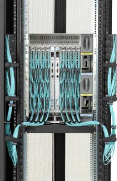
Horizontal cable managers are excellent for any kind of cable – fiber, coax, patch cables, copper wiring and more to ensure that your cables are well-organized and protected. Horizontal cable managers come with rack-mountable 1U or 2U design, and some of them are built with finger duct and D-rings for easier finger access in server rack.

2. Vertical Cable Manager

Vertical cable manager work very well to organize and hold cables to ensure proper air flow, avoiding overheating in complex server rack environment. They’re also great for installations where you need to save space or need to make more room in the future to expand your network.

3. Cable Hangers and Trays

If you need to organize cabling within server racks, cable hangers can come in handy. Cable trays are excellent for running wires from one place to another and can be mounted on the floor or overhead in the ceiling.

4. Copper Patch Panels

For data and telecommunications networks a copper patch panel is essential. A patch panel is a board with a number of different ports to connect network wiring. Ethernet patch panels are available in a variety of different configurations depending on your cable types and needs: there are Cat5e patch panel, Cat6 patch panel and Cat6a patch panel, each with different port counts such as 24-port patch panel, 48-port patch panel, etc. Copper patch panel is also great for consolidating cables so that your server rack looks neat and organized.

5. Fiber Optic Patch Panels

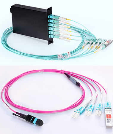
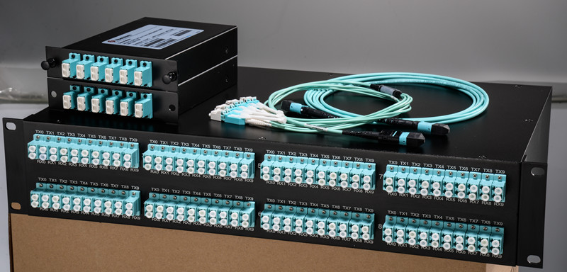
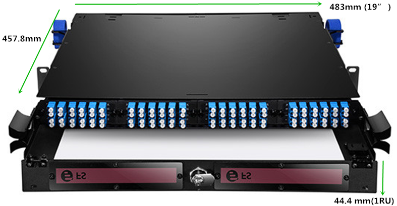
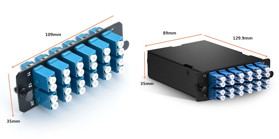
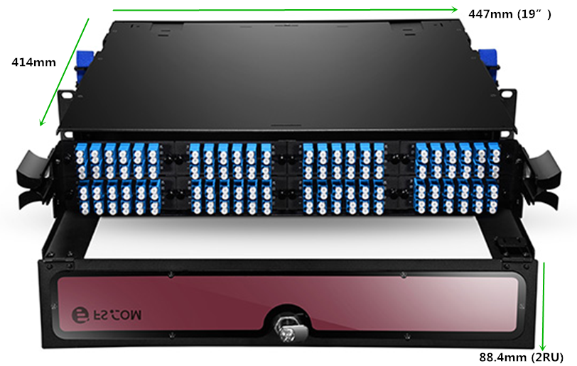
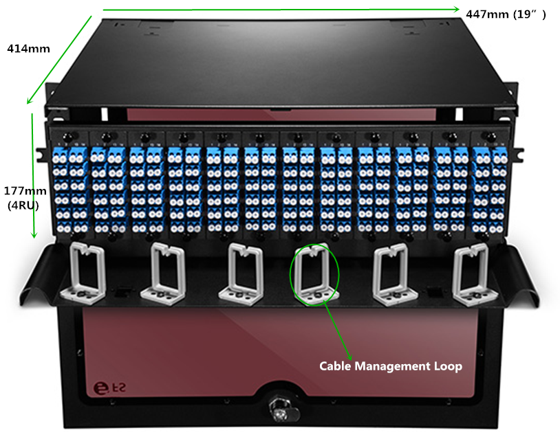
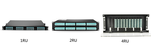
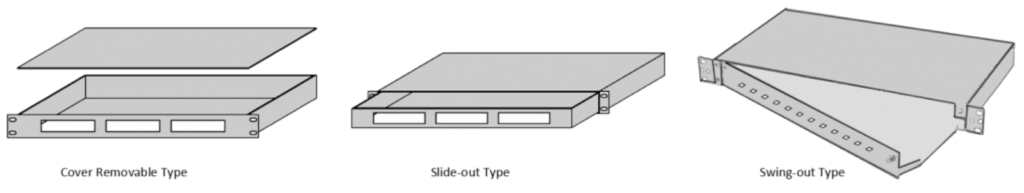
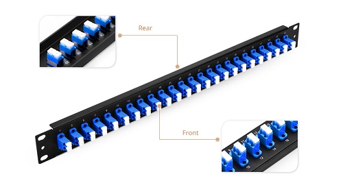
Similar to data patch panels, fiber patch panels are designed specifically for fiber optic cables. Also known as termination units they can accommodate connectors, patch cables and more. Network technicians can easily connect cable fibers through cross connection, test the cable patch panel, and connect it to other network equipment. Grouping by the connector type, there are single mode and multimode LC/SC/MTP fiber patch panels with various port counts. You can also choose blank patch panel to mix and match your fiber and copper cabling.

Conclusion

Effective server rack management helps to improve physical appearance, cable traceability, airflow, cooling efficiency and troubleshooting time while eliminates the chance for human error. Hope our guide on server rack cable management would help solve your problem. FS.COM provide tailored cable management solutions for our customers, as well as management tools like cable manager, patch panelcable organizer and cable tie. If you need any help, please contact us at sales@fs.com.

Cable management: MTP Modules and Harnesses in Data Center

Share

Traditional optical cable management such as duplex patch cords and duplex connector assemblies work well in application-specific, low-port-count environments. But as port counts scale upwards and system equipment turnover accelerates, these cable managements become unmanageable and unreliable. Deploying a modular, high-density, MTP-based structured wired cabling system in the data center will significantly increase response to data center moves, adds and changes (MACs). Knowledge of MTP modules and MTP harnesses will be provided in this blog.

Introduction to MTP Modules and Harnesses 
An obvious benefit to deploying a MTP-based optical network is its flexibility to transmit both serial and parallel signals. MTP to duplex connector transition devices such as modules and harnesses are plugged into the MTP trunk assemblies for serial communication. MTP Modules are typically used in lower-portcount break-out applications such as in server cabinets. MTP harnesses provide a significant increase in cabling density and find value in high port count break-out situations such as SAN Directors (see figure below). The built-in modularity of the solution provides flexibility to easily configure and reconfigure the cabling infrastructure to meet current and future networking requirements. MTP harnesses and modules can be exchanged or completely removed from the backbone network to quickly adapt to data center MACs.

mtp-modules-harnesses

MTP Modules in Data Centers
MTP modules typically are placed in a housing located in the cabinet rack unit space. Here the MTP trunk cable is plugged into the back of the module. Duplex patch cords are plugged into the front of the module and routed to system equipment ports. Integrating the MTP modules cabling solution into the data center cabinet can enhance the deployment and operation of the data center cabling infrastructure. As shown in the figure below, integrating the MTP modules into the cabinet vertical manager space maximizes the rack unit space available for data center electronics. MTP modules are moved to the cabinet sides where they snap into brackets placed between the cabinet frame and side panel. Properly engineered solutions will allow MTP modules to be aligned with low-port-count system equipment placed within the cabinet rack unit space to best facilitate patch cord routing.

mtp-modules

MTP Harnesses in Data Centers
MTP harnesses are plugged into the backbone MTP trunk assemblies through an MTP adapter panel. The MTP adapter panel is placed in a housing that is also typically located in the cabinet rack unit space. MTP to LC 12-fiber break-out harnesses plug into the front of the adapter panels and are routed over to the director line cards where the LC duplex ends are plugged into the line card ports (see figure below). These MTP harnesses are pre-engineered to a precise length with strict tolerances to minimize slack, while a small outside diameter allows for easy routing without preferential bend concerns. With a pre-engineered cabling management, not only is installation simplified, but the time required for SAN design and documentation is greatly reduced with port mapping architecture inherent to the design.

mtp-harnesses

Conclusion
The move from the traditional low-density duplex patch cord or assembly cabling management solution to a high-density MTP module and harnesses cabling management solution integrated into the cabinet vertical manager enables the physical layer to be implemented in a manner that provides a flexible and reliable cable management in the data center. FS.COM MTP cassette provide a quick and efficient way to deploy up to 24 LC or 12 SC fiber ports in a single module. Modules are available in multimode (62.5/125 and 50/125) and single-mode cable. MTP harnesses in FS.COM are available in 8-fiber MTP to LC breakout cable, 12-fiber MTP to LC breakout cable and MTP to 24-fiber LC for your options. For more information, please feel free to contact us at sales@fs.com.

High Density Rack Mount Fiber Patch Panel for Fiber Adapter Panels & MTP Cassettes

Share

When you’re dealing with fiber optic patch cables in your network, whether your installation is small or large, simple or complex, your fiber patch cables have to terminate somewhere, so make sure you’ve got the right fiber patch panel solution designed specially to protect them. As we know, fiber patch panels are either for patching or splicing applications. For patching fiber patch panel, which can hold either fiber adapter panels (FAPs) or MTP cassettes. Usually, a standard 1RU rack mount enclosure can hold 3 LGX FAPs or cassettes, however, a high density 1RU rack mount fiber patch panel can hold 4 HD FAPs or cassettes, which efficiently optimize space utilization and save more cost in rack cable management.

fiber-enclosures

Fiberstore’s FHD series high density rack mount fiber patch panel, including 1RU (FHD-1UFCE), 2RU (FHD-2UFCE) and 4RU (FHD-4UFCE) types, are designed to hold both FAPs and cassettes and can easily mount in EIA 19-inch racks or cabinets, which provide a comprehensive line of fiber distribution enclosures that provide a high density flexible and modular system for managing fiber terminations, connections, and patching in data center application to maximizing rack space utilization and minimizing floor space.

FHD-1UFCE—High Density 1RU Rack Mount Fiber Patch Panel

HD FAPs is an unloaded 1RU rack mount fiber patch panel that can support either 4 FHD fiber adapter panels or 4 FHD MTP modular cassettes, up to 96 fibers. Inside the fiber patch panel, you can install either slack spools or splice trays for patching applications or splicing applications, which provides a complete system solution for connectivity. As shown in the figure below, its size is 44.4mm(H)x483mm(W)x457.8mm(D). Besides the FHD-1UFCE, we also provide pre-loaded 4 FHD fiber adapter panels fiber patch panel.

High Density 1RU Rack Mount Fiber Enclosures

  • Related FHD Adapter Panel & FHD MTP Modular Cassette Size

Fiber Adapter Panels and MTP Cassettes

FHD-2UFCE—High Density 2RU Rack Mount Fiber Patch Panel 

FHD-2UFCE is an unloaded 2RU rack mount fiber patch panel that can support either 8 FHD fiber adapter panels or 8 FHD MTP modular cassettes, up to 192 fibers. Inside the fiber patch panel, you can also install either slack spools or splice trays for patching applications or splicing applications, which provides higher patch field density in fewer rack units saving valuable space. As shown in the figure below, its size is 88.4mm(H)x447mm(W)x414mm(D).

High Density 2RU Rack Mount Fiber Enclosures

FHD-4UFCE—High Density 4RU Rack Mount Fiber Patch Panel

FHD-4UFCE is an unloaded 4RU rack mount fiber patch panel that can support either 12 FHD fiber adapter panels or 12 FHD MTP modular cassettes, up to 228 fibers. Splice tray, cable management loops and slack spools accessories of FHD-4UFCE are simple, which assures flexibility and ease of network deployment and moves, adds, and changes. As shown in the figure below, its size is 177mm(H)x447mm(W)x414mm(D).

High Density 4RU Rack Mount Fiber Enclosures

No matter where your cabling is, or what function you need your fiber patch panel to deliver, FS.COM has the ideal fiber patch panel solution. Our fiber patch panels are available in any configuration and feature industry-leading port density. Both rack mount and wall mount fiber patch panel for single-mode and multimode applications are available. All fiber patch panels are highly adaptable and easy-to-configure design, holding FAP Adapter Panels or MTP Cassette with superior cable management, port identification, fiber accessibility and security.

How to Choose the Right Rack Mount Fiber Enclosure?

Share

Fiber enclosure can provide easy-to-manage cabling environments and strong protection for fiber optic cables. Since more and more cables used in today’s data centers, high-density cable management tools also become more popular and essential than before. However, there are so many fiber enclosure manufacturers and suppliers, and the rack mount fiber enclosures supplied therefore available in different sizes and applications. How to choose the rack mount fiber enclosures for your network?

Rack Mount Enclosures Configurations
The rack mount enclosure is generally made for standard 19 inch rack mounting. Depending on the number of connections required, they are available in one or more rack units (RU) height configurations, such as 1RU, 2RU or 4RU, etc. See the picture below, you should choose the most proper one depending on space and port requirement of your network.

fiber enclosures

Rack Mount Enclosures Mount Types
1RU rack mount fiber enclosures are the most commonly used size in data center server racks cable management. For convenient installation and cable management, there are cover removable, slide-out and swing-out three mount types fiber enclosures to choose from. The cover removable type is an early type of fiber enclosures. If your budget is sufficient, I will recommend you to use the slide-out type or swing-out type though they are more expensive than the cover removable type. But you may get more benefits during installation and maintenance, as they respectively feature a convenient slide-out support tray and an integrated swing-out tray so that you don’t need to remove the whole enclosure from the rack to gain internal access.

222

Rack Mount Fiber Enclosures Applications
Fiber enclosure has various designs and applications. There are mainly three ways to use the fiber enclosures, which are depended on the accessories that are installed on the fiber enclosure. The following will take a slide-out 1RU rack mount fiber enclosure as example to illustrate the applications of the fiber enclosures in data center. Installed with splice trays, fiber adapter panels and MTP cassettes separately, fiber enclosure can provide cabling environment for different connections.

Application 1: Installing splice tray and FAPs
Installing four fiber adapter panels on the front panel and one or more splicing trays inside the enclosure drawer. This fiber enclosure can provide cable management and protection for splicing joints and connections.

splice tray and fiber adapter panels
Application 2: Installing Spools and FAPs
Installing two spools on the enclosure drawer and four FAPs on the front panel, this fiber enclosure can provide flexible high density cabling for fiber patch cables.

Spools and fiber adapter panels
Application 3: Installing HD MTP Cassettes
Up to four MTP Cassettes can be installed in this 1U fiber enclosure, which can provide 40G/100G to 10G high cabling density and easy transferring from MTP interface to LC interface.

MTP Cassettes

Conclusion
After reading the passage, we know that rack mount fiber enclosures may be available in different sizes, mount types and applications. Thus to choose a right fiber enclosure seems not a simple thing. FS.COM offers a wide range of rack mount enclosures, as well as custom service, which can help address all kinds of your requirements. For more details, please contact us via sales@fs.com or call 24/7 Customer Service: 1 (718) 577 1006.

Related Article: Upgrade to 40G / 100G Networks with High-Density Fiber Enclosures

Three Kinds of Polarity Reversal Methods of LC Uniboot Patch Cords

Share

As the networking environment of today becomes increasingly dependent on high-speed and high-density solutions, effective cable management is a real problem. The challenge is how to manage more cables in a smaller amount of space. The LC uniboot patch cord utilises a special “round duplex” cable that allows duplex transmission within a single 2.4mm or 3.0mm cable, which reduces cable management space by up to 70% comparing to standard LC patch cords. Besides, it has a unique polarity reversal design allows the fiber polarity to be easily switched without the use of any tools. In today’s LC uniboot patch cords market, there are usually three methods to reverse the polarity.

Method One
1. Open connector top.

11
2. Switch the polarity.

22
3. Close connector top.

33

Method Two
1. Locate trigger housing on LC uniboot connector and pull towards the boot.

1
2. Open trigger housing is resting on the boot turn each LC connector to the outside 180 degrees one at a time.

888
3. Complete the polarity reversal by turning the resting trigger housing 180 degrees around boot and click into LC until you hear a click.

000

Method Three
1. Connector Polarity
Uncrossed lines under the connector latch on the housing at both ends indicates uncrossed fiber polarity A-B/B-A.

1
2. Unlock Front Housing on One End
Push the keys on either side to unlock the housing to remove the front section of the Uniboot housing.

2

3. Remove Front Housing
Slide the front housing away from the rest of the Uniboot.

3
4. Rotate Front Housing
Flip the released section of the housing. Do not rotate or twist the fiber.

4
5. Attach Front Housing
Push the housing back over the ends and the rest of the Uniboot connector until it clicks back into place.

5
6. Connector Polarity
Finished result should now show crossed lines under the flipped connector latch and uncrossed lines on the unaltered end. This would indicate a crossed fiber polarity A-A/B-B.

6

Different kind of LC uniboot patch cords may have different polarity reversal design, therefore we must use different method to change the polarity. When you choose to use LC uniboot patch cords in your network, keep in mind to take the polarity reversal methods in to consideration. FS.COM LC uniboot patch cords (easily reverse the polarity with method one) terminated with premium grade zirconia ceramic ferrule connectors which help assure high transmission quality and low optical power loss and offer improved airflow and visibility of equipment within a high-density network environment.

Video Patch Panel With Patch Cable

Share

The jacks commonly used in patch panels in the U.S. conform to Western Electric standard dimensions. The number of insertion cycles a jack can endure should be rated in the tens of thousands. The factors affecting the life and reliablility of a jack include contact wear and failure of the termination switch. Descirable features include the following:

● Contacts fully isolated from the panel.
● Sealed metal housing to keep out contaminants and provide EMI protection.
● Easy replacement from the front of the panel.
● Low VSWR (below 600 MHz)
● High signal isolation (40 dB)
● 75 Ω characteristic impedance.
● Wide designation strips, making it easier to label the field and to allow more flexibility in selecting names that will fit on the lables.

If a patch cable is inserted in the signal path of a timed video system, it will delay the signal by an amount determined by its length and physical properties. The patch thereby alters the timing of the signal path. This can be avoided by using phase-matched normal-through fiber patch panels. The design of these patch panels anticipates the delay caused by a fixed length of patch cable by including that length in the loop-through circuit.

With phase-matched panels, the normaling connection in each connector module includes a length of cable that provides a fixed delay through the panel, usually 3 ft (0.914m). If a patch cord of the same length as the internal cable is used to make connections between patch points, the delay will be the same as that of the normal-through panel. When a fiber optic patch cord is plugged in, it is substituted for the loop cable through the swiching mechanism normally used in normalled patch connectors. Thus, critical timing relationships can be maintained.

In a normal uncompensated patch panel, when a cable is used to patch between two points on the panel, the length of the patch cord is added to that of the cables connected to the patch. The additional cable length delays the signal by approximately 1.52 ns/ft (5 ns/m). To avoid the delays associated with conventional patch panels, phase-matched normal-through video patch panels should be used.

If phase-matched patch panels are used, all of the patch cord must be the same length as the delay built into the patch panel. Obviously, if all of the patch cords must be the same short length for the phase-matched panel, it would not be possible to patch between panels that are separated by a longer distance than the cord can reach. This limitation should be considered when laying out patch panels in a fiber enclosure.

Color-coded cables can be specified. When different-length patch cords are specified, different colors can be used to distinguish one length from another for better cable management.

Fiberstore specializes in fiber optic patch cable assemblies and fiber optic network devices manufacturing since 1995, we are known as the fiber optic cable manufacturer for the excellent products quality, competitive prices, fast delivery and good service.  Our fiber optic cables are available with combinations of LC, SC, ST, FC, and MTRJ connectors and come in 1, 2, 3, 5, and 10 meter lengths (and OM3 cables up to 30 meters).  We offer LC fiber optic cable, SC fiber optic patch cables, SC LC fiber patch cable ect. We not only offer OEM fiber optic patch cord assemblies to some world leading companies in this industry, but  also cooperate with many other companies from all over the world and support these partners to win in the market.

Punch-Down Block and Patch Panel

Share

The cable runs in a structured cabling environment terminate in a punch-down block, which is usually a 66-block or a 110-block, or BIX- or Krone-style blocks, “Cabling System Connections and Termination.” The 110-block is most commonly used for voice and data cabling termination, although you will find many installations that use a 110-block for termination voice systems and patch panel for terminating data systems. Punch-down block termination provides a cross-connect from one cable set to another, allowing for easier moves, adds, and changes (MACs) as the need arises.

What Is A Punch-Down Block?

A punch-down block is mounted to a backboard, which is usually made of plywood and secured to the wall of a TC. If you install cabling on more than the floor, each floor must have a separate punch-down block with terminations for the cable drops from the higher floors. Backbone cables should be installed with 10-foot service coils at the termination points, which are commonly located on the backboard in the closet. Figure 1 illustrates a typical TC.

Install patch cables from the punch-down block to a patch panel. The purpose of the patch panel is to connect the backbone system to networking equipment such as a hub or router. End-user equipment, which includes workstations, network printers and scanners, and other shared electronic equipment, generally connect to a hub (also called a concentrator) or router via RJ-45 cable jacks or outlets.

There are pros and cons to using cross-connect blocks. They offer higher densities and require less space than patch panels, and also are less expensive. On the other hand, they are the least friendly for making moves, adds, and changes to the configuration. Skill is involved in removing and rea-ranging cables. When using patch panels, almost anyone can rearrange the system. In both situations security, ease of attachment, expense, and physical space are all considerations.

What Is Fiber Optic Patch Panel?

Fiber optic patch panel is commonly used in fiber optic management unit. When you install and manage the fiber optic links, you may encounter hundreds or even thousands of fiber optic cables and cable connections, fiber optic management products are used to offer space and protection for the fiber cables and cable links, and they make it easier for the cable management and troubleshoot work. Our fiber optic patch panels are all sliding type, they are compatible to use with equipment and cable assembly products from other companies. Now you can see the two products from our store. They are SC fiber patch panel, 24 Port Fiber Patch Panel.

12 port  OS1/2 9μm Duplex Plastic SC Fiber Patch Panel

Features of FS001 SERIES MOLDED

● Compatible with Leviton fiber adapter panels
● Adapter panels offered in LC, SC, ST, and blank styles, fit for all Opt-X rack-mount and wall-mount enclosures and VertiGO® panels
● Equipped with plastic dust caps to make connecting panels tool-free and efficient
● Integrated couplers eliminate “rattle” and loose fit
● Captive push-lock pins allow for quick tool-less installationCaptive push-lock pins allow for quick tool-less installation
● Exceeds optical performance standards and meets all other applicable standards

12 pack LC Duplex 24 Port Fiber Patch Panel Blue

24 port Patch Panel

● Compatible with BlackBox Fiber Adapter Panel
● Adapter panels snap easily into all standard fiber enclosures, cabinets, and patch panels, including all Black Box® models.
● High-density panels with ST or LC connectors are available.
● The easy way to patch fiber cables to termination enclosures

We supply many fiber optic patch panels. They are with types to fit from 12 fibers to 72 fiber management demand. These fiber optic patch panels are with optional various kinds of fiber optic adapters and fiber optic pigtails, types including SC, LC, ST, FC, MU, E2000, etc.  We have a number of different customizable options available to fit whatever application you require. With products compatible with trusted brands including Black Box, Wirewerks, Mr-technologies, Corning, Leviton, Panduit Opticom adapter panel and more.