Author Archives: Amelia.Liu

The Basic Parameters of Passive Optical Network Devices

Share

There are many devices elementary but necessary for the Passive Optical Network (PON) applications that require the transmission, combining, or distribution of optical signals. These passive devices include the Optical Splitter/Coupler, Optical Switch, Optical Attenuator, Optical Isolator, Optical Amplifier, and WDM Filters (CWDM/DWDM Multiplexer) etc. Tips: The passive devices are components that do not require an external energy source.

When working with these passive devices it is important to have a basic understanding of common parameters. Some of the basic parameters that apply to each device are Optical Fiber Type, Connector Type, Center Wavelength, Bandwidth, Insertion Loss (IL), Excess Loss (EL), Polarization-Dependent Loss (PDL), Return Loss (RL), CrossTalk (XT), Uniformity, Power Handling, and Operating Temperature.

Connector Type and Optical Fiber Type

Many passive devices are available with receptacles or fiber optic pigtails. The pigtails may or may not be terminated with a fiber optic connector. If the device is available with a receptacle or connector, the type of receptacle or connector needs to be specified when ordered. You should also note the type of optical fiber used by the manufacturer of the device to ensure it is compatible with the optical fiber used for your application.

Center Wavelength and Bandwidth

Center Wavelength is the nominal operating wavelength of the passive device.

Bandwidth (or bandpass) is the range of wavelengths over which the manufacturer guarantees the performance of the device. Some manufacturers will list an operating wavelength range instead.

Types of Loss

  • IL is the optical power loss caused by the insertion of a component into the fiber optic system. When working with passive devices, you need to be aware of the IL for the device and the IL for an interconnection. IL as stated by the manufacturer typically takes into account all other losses, including EL and PDL. IL is the most useful parameter when designing a system.
  • EL may or may not be defined by the manufacturer. EL associated with fiber optic couplers, is the amount of light lost in the coupler in excess of the light lost from splitting the signal. In other words, when a coupler splits a signal, the sum of the power at the output ports does not equal the power at the input port; some optical energy is lost in the coupler. EL is the amount of optical energy lost in the coupler. This loss is typically measured at the specified center wavelength for the device.
  • PDL is only a concern for Single-Mode passive devices. It is often the smallest value loss, and it varies as the polarization state of the propagating light wave changes. Manufacturers typically provide a range for PDL or define a not-to-exceed number.
  • RL, short for Return Loss or Reflection Loss, is typically described as this: when a passive device is inserted, some of the optical energy from the source is going to be reflected back toward the source. RL is the negative quotient of the power received divided by the power transmitted.

Tips: IL, EL, PDL, RL are all measured in decibels(dB).

CrossTalk (XT)

XT in an optical device describes the amount of light energy that leaks from one optical conductor to another. XT is not a concern in a device where there is a single input and multiple outputs. However, it is a concern with a device that has multiple inputs and a single output, such as an optical switch. XT is also expressed in dB, where the value defines the difference between the optical power of one conductor and the amount of leakage into another conductor. In an optical switch with a minimum XT of 60 dB, there is a 60 dB difference between the optical power of one conductor and the amount of light that leaked from that conductor into another conductor.

Uniformity

Uniformity is a measure of how evenly optical power is distributed within the device, expressed in dB as well as XT. For example, if a device is splitting an optical signal evenly into four outputs, how much those outputs could vary from one another is defined by uniformity. Uniformity is typically defined over the operating wavelength range for the device.

Power Handing

Power Handling describes the maximum optical power at which the device can operate while meeting all the performance specifications defined by the manufacturer. Power handling may be defined in mW(milliwatt) or dB, where 0 dBm is equal to 1 mW.

Operating Temperature

Operating Temperature describes the range of temperatures that the device is designed to operate in. This can vary significantly between devices, because some devices are only intended for indoor applications while others may be used outdoors or in other harsh environments.

Article Source: http://www.fiberopticshare.com/the-basic-parameters-of-passive-optical-network-devices.html

Fiber Optic Cable Circuit Also Need Lightning Protection

Share

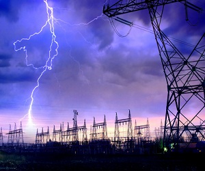
Some time ago a customer bought the fiber optic cable from fs.com, but he asked me if it can be used in frequent areas of lightning and if he needs to lightning protection. Well, As for this problem, I give the customer this explanation.

Suitable cable barrier property makes its lightning protection is not so obvious as coax and open cable circuit. And in the process of rapid development of fiber optic cables, safety grounding is often misunderstood and even forgotten. With a large number of adoptions of optical fiber cable, the situation of the fiber optical cable circuit from lightning often occurs these years. Fiber optic cable circuit has a great deal of capacity and the easiest links that be lightning struck is buried links, and it is also difficult to repair, so once it is in trouble, will cause huge losses. This page mainly introduces the fiber optic cable circuit lightning protection.

Fiber Optic Cable Lightning Protection

Fiber optic cable has no electrical conductivity, can protect from impact current, but in order to male high capacity optical cables from environmental events, fiber optic cables must have armored cable components and when electric line close to short and a lighting strike, people will feel current ac or surge current, harm the safety or damage the link road equipment. Related product: adss fiber.

Lightning has the trend to find the minimum impedance path to bleed thundercloud charge opposite charges neutralize underground. When lightning the land or buildings, lightning point potential while the cable extends to the very far, far end can be regarded as a potential 0, so the potential of lightning strikes near the cable is also regarded as 0. Such colony formation and fiber optic cable between the lightning point of great potential difference, the potential difference exceeds the compressive strength of Jiang Lei point between the outer sheath of the cable will breakdown the outer sheath formed from lightning point to the metal components arc channel, so a lot of lightning current flock to the cable, causing serious damage to the cable. ? It is the time to use optical fiber cable st termination kit. Cable lines in the construction inevitably damage PE (polyethylene) jacket, another rat-bite, external staff may cause the cable exposed metal components. These points will be easy to expose a strong electrical charge is introduced or lightning cable, causing damage.

According to relevant data show that in the following cases, cable lines susceptible to lightning strikes:

  • Metal sheaths, strengthen the core or the insulation lower copper cable.
  • Mutation terrain, soil resistivity changes in the larger area.
  • Cable trees or tall buildings with a single gauge are not enough time.

According to the above analysis, the same cable line to be concerned about its main work. Fiber optic cable lines for lightning protection, can target local weather and terrain and other natural conditions, a targeted manner. After analysis of a few lightning cable, I found that the cable line construction and maintenance should pay attention to the following questions.

aerial cable

First, as for aerial cables, one of the outdoor fiber optic cable, the connector box usually has to the structure of the core can be broken even, whether using electrical connected or disconnected, metal pressure plate structure is superior to the self-contained bolt connection, and the self-contained horizontal hole is better than vertical slot structure, it is a problem that should be paid attention to when choosing connector box.

Second, for underground cable lines protection, first of all, station grounding method, in the joint of the metal part of the cable shall be connected, the relay length of cable, moisture proof layer, strengthens core armored layer connected state.In both ends (station), the wrong layer, reinforcement, they can moisture proof layer should be through the arrester grounding.

Related Article:  Which Patch Cable Should I Choose for My Optical Transceiver?

Some Developments that May Occur in the Fiber Amplifier

Share

This page will focus on fiber optic amplifiers?application, and obviously, the introduction of EDFA in a long distance network has been the first, application identified by several telecom’s operators. I just think EDFA’s advantage is that using the existing cable from 565 Mbit/s systems. Into a 2400 Mbit/s without any additional electronic requirement, maybe this is one of the cost/performance ratio advantage of the optical amplifier versus the conventional technologies. Other applications arise from those countries where the telecommunication network infrastructures are poor, or even non existing. In such a situation the possibility to reach a distance in the order of 200km at 140 or 565 Mbit/s makes the use of EDFA more competitive.

Optical amplification has been already successfully tested in various laboratories and field trials in Europe, North America and Japan. Worldwide standards authority is still working on the standardization of EDFA optical amplifier. Major telecom manufactures already supply line terminals with integrated optical amplifier functions. As far as the future submarine links are concerned, it is expected that in a few years, because of optical amplification, the electronical of today submerged repeaters, will be amended by replacing all optical amplifiers.

Well, an example of the power budget calculations at 2400 Mbit/s is given in the annex, where an EDFA system composed by a power amplifier and a pre-amplifier has been considered. In combination with a dispersion shifted submarine fiber optic cable, it belongs to outdoor fiber optic cable. Junction Networks. The massive introduction of SDH systems, and the forecast use of it on the existing cables, has made the use of EDFA technologies achievable also in the junction networks area. In Europe, North America and Japan, this possibility will be limited to the intercity applications.

In connection with the subscriber loop network design, a similar range of products is drawn up by the worldwide industry for the next generation of CATV systems. It is CATV amplifier. In a near future optical transmitters with Booster Amplifier? integrated in the same equipment, will need to be able to transmit up to 60/80 television channels simultaneously, in a cluster of 200/300 subscribers each. The figure showed a?Booster EDFA Optical Amplifier.

edfa

Although CATV amplifier housing employed in current CATV networks is designed to accommodate a return path amplifier, most of today’s CATV system have unactivated return channels. Roughly 20 percent of today’s CATV systems use some fiber optic links to bypass slow amplifier chains in the trunk portion of the network. Service is typically provided to residences and apartments, with relatively limited business locations connected to CATV networks. Similar applications product has WDM amplifier. In-line amplifier, just differ in the range of applications. There is usually only a single CATV operator in a given service area, with nascent competition from microwave and direct broadcast satellite service providers. Television receives only background antennas that are 1 to 2 meters in diameter are used by a small fraction of residential customers. With the fast developments of fiber optical amplifiers, I am very bullish on the trend of it, hope it can be dragged out more widely features and bring more benefits to people.

Related Article:  Which Patch Cable Should I Choose for My Optical Transceiver?

One Small Problem When We Choose the Fiber Patch Cable

Share

There is a common phenomenon that people are always able to distinguish different types of interfaces easily after corresponding to the given pictures, but when we choose the fiber patch cable, such as the polishing type also confused them, it shows UPC or APC, also confused us, recently I finally understand it and share my ideas with you.

First we can look from the definition, the above are acronyms for the following:

    • UPC – Ultra Physical Contact
    • APC – Angled Physical Contact

Only from the words we can have a simple understanding of them, in order to have a deeper understanding, there i named a few examples for you. Usually when we hear about the description like “fiber patch lc apc lc upc”, “e2000 fc apc”, “sc apc to sc upc single mode 9 125 simplex fiber optic patch cord cable”, what do this words apc upc mean? Then we will give you explanations. In Fiberstore, We use different color to distinguish them, the blue is UPC connector and the green is APC connector, shown as the figure.

In fact, it stands for the polish style of fiber optic core and connect the copper connector of copper cable as medium, and we need to know that the connections between the fiber optic connector and the ceramic core. Different fiber optic connector ring’s size, length and polished style is different, different polish of the fiber optic connector rings result in different performance, mainly on the back reflection. Generally, UPC is 50dB or higher and APC is 60dB or higher. All insertion loss of that they should be less than 0.3dB and the lower insertion loss is, the better performance they have, it is the reason why UPC connector is more widespread than APC. At the same time, there is a point we need to pay attention to, we all know that fiber optic cables can be divided into single mode and multimode fiber cables, but single mode fiber optic cables can be with UPC or APC polished connectors, while multimode fibers are not made with APC connectors. When we talk about the insertion loss, fiber optic attenuators have to be mentioned, it also has the diffent db to choose, as for the more knowledge about it, please always pay close attention to.

Fiberstore, you know, it offers kinds of fiber cables to choose, the different connector series all available for UPC/APC version, and we can also provide SM, MM, OM3 cables, simplex and duplex option, 0.9mm, 2.0 mm, 3.0mm cable diameter for choose, as for the fiber length, it can be customized according to your requirements.

Related Article:  Which Patch Cable Should I Choose for My Optical Transceiver?

The More and More Mature Fiber Optic Cables Transmission Technology

Share

Fiber optic media are any network transmission media that generally use glass, or plastic fiber in some special cases, to transmit network data in the form of light pulses. Within the last decade, optical fiber has become an increasingly popular type of network transmission media as the need for higher bandwidth and longer spans continues.

Fiber optic technology is different in its operation than standard copper media because the transmissions are “digital” light pulses instead of electrical voltage transitions. Very simply, fiber optic transmissions encode the ones and zeroes of a digital network transmission by turning on and off the light pulses of a laser light source, of a given wavelength, at very high frequencies. The light source is usually either a laser or some kind of Light-Emitting Diode (LED). The light from the light source is flashed on and off in the pattern of the data being encoded. The light travels inside the fiber until the light signal gets to its intended destination and is read by an optical detector.

Fiber optic cables are optimized for one or more wavelengths of light. The wavelength of a particular light source is the length, measured in nanometers (billionths of a meter, abbreviated “nm”), between wave peaks in a typical light wave from that light source. You can think of a wavelength as the color of the light, and it is equal to the speed of light divided by the frequency. In the case of Single-Mode Fiber (SMF), many different wavelengths of light can be transmitted over the same optical fiber at any one time. This is useful for increasing the transmission capacity of the fiber optic cable since each wavelength of light is a distinct signal. Therefore, many signals can be carried over the same strand of optical fiber. This requires multiple lasers and detectors and is referred to as Wavelength-Division Multiplexing (WDM).

Typically, optical fibers use wavelengths between 850 and 1550 nm, depending on the light source. Specifically, Multi-Mode Fiber (MMF) is used at 850 or 1300 nm and the SMF is typicallyused at 1310, 1490, and 1550 nm (and, in WDM systems, in wavelengths around these primary wavelengths). The latest technology is extending this to 1625 nm for SMF that is being used for next-generation Passive Optical Networks (PON) for FTTH (Fiber-To-The-Home) applications. Silica-based glass is most transparent at these wavelengths, and therefore the transmission is more efficient (there is less attenuation of the signal) in this range. For a reference, visible light (the light that you can see) has wavelengths in the range between 400 and 700 nm. Most fiber optic light sources operate within the near infrared range (between 750 and 2500 nm). You can’t see infrared light, but it is a very effective fiber optic light source.

Above: Multimode fiber is usually 50/125 and 62.5/125 in construction. This means that the core to cladding diameter ratio is 50 microns to 125 microns and 62.5 microns to 125 microns.  There are several types of multimode fiber patch cable available today,  the most common are multimode sc patch cable fiber, LC, ST, FC, ect.

Tips: Most traditional fiber optic light sources can only operate within the visible wavelength spectrum and over a range of wavelengths, not at one specific wavelength. Lasers (light amplification by stimulated emission of radiation) and LEDs produce light in a more limited, even single-wavelength, spectrum.

WARNING: Laser light sources used with fiber optic cables (such as the OM3 cables) are extremely hazardous to your vision. Looking directly at the end of a live optical fiber can cause severe damage to your retinas. You could be made permanently blind. Never look at the end of a fiber optic cable without first knowing that no light source is active.

The attenuation of optical fibers (both SMF and MMF) is lower at longer wavelengths. As a result, longer distance communications tends to occur at 1310 and 1550 nm wavelengths over SMF. Typical optical fibers have a larger attenuation at 1385 nm. This water peak is a result of very small amounts (in the part-per-million range) of water incorporated during the manufacturing process. Specifically it is a terminal –OH(hydroxyl) molecule that happens to have its characteristic vibration at the 1385 nm wavelength; thereby contributing to a high attenuation at this wavelength. Historically, communications systems operated on either side of this peak.

When the light pulses reach the destination, a sensor picks up the presence or absence of the light signal and transforms the pulses of light back into electrical signals. The more the light signal scatters or confronts boundaries, the greater the likelihood of signal loss (attenuation). Additionally, every fiber optic connector between signal source and destination presents the possibility for signal loss. Thus, the connectors must be installed correctly at each connection. There are several types of fiber optic connectors available today. The most common are: ST, SC, FC, MT-RJ and LC style connectors. All of these types of connectors can be used with either multimode or single mode fiber.

Most LAN/WAN fiber transmission systems use one fiber for transmitting and one for reception. However, the latest technology allows a fiber optic transmitter to transmit in two directions over the same fiber strand (e.g, a passive cwdm mux using WDM technology). The different wavelengths of light do not interfere with each other since the detectors are tuned to only read specific wavelengths. Therefore, the more wavelengths you send over a single strand of optical fiber, the more detectors you need.

Related Article:  Which Patch Cable Should I Choose for My Optical Transceiver?

The LC Connector in Fiber Management and Transceivers

Share

The LC connector system, standardized as TIA/EIA FOCIS-10, was designed specifically to address the needs of increasing network interconnect density.

In the past, fiber management systems (for D4, ST, FC and Biconic),have required twice as many individual connectors as copper systems, hence, crowding racks and closets (Fig. 2) with additional patch bays, management hardware and line terminating electronics. SFF connectors have either a unitary body design (FJ and MT-RJ) or a provision for clipping simplex connectors together to form a single SFF end (LC).

The LC connector provides the potential for twice the interconnect density in closets and racks when compared to a SC connector. Although, there is a point at which additional density cannot be utilized because of the difficulty in fiber routing inordinately large cable counts. Also at issue in these higher density racks, is the problem of disturbing adjacent circuits in MACs. Most important in fiber management, is the decreased footprint of the LC on electronics (hubs, switches, etc.) for fiber transceivers.

SFF Connector, SFP Transceivers and the march towards 10Gb/s Enterprise Networking

Original SFF transceivers (GBICs) on equipment have now been overshadowed by the SFP (“pluggable”versions of the SFF) transceiver. Equipment vendors are starting to offer SFP on switches/NICs for Gb/s Ethernet. The optical receptacle on the SFP for Fibre Channel and Gb/s Ethernet is the LC connector. Most major transceiver vendors, including early proponents of “MT-RJ-only” transceivers, now sell SFPs with the LC interface only.

On 200 pin XenPAK transceivers, only SFF options are specified in the Multi Source Agreement (MSA). Vendors have offered XenPAK with both SC and LC pigtails, but the majority offers “LC only” XenPAK product lines. The LC is also used in competing transceivers such as XenPAK, X2 and XFP.

LC Market Acceptance

The LC is the market leader in SFF connectors. Press releases from the major vendors of LCs (Lucent) and MT-RJs (Tyco/AMP) in similar time frames (mid 01) indicate unit volumes of 20 million and 3 million respectively.

According to the Fiber Optic Connector/Mechanical Splice Global Market Report by Electronicast, the North American Market for private network use of SFF connectors is expanding quite rapidly. In this report, the multimode LC is estimated to grow at double the rate of that of the multimode MT-RJ (Table 1). The difference embedded in the Electronicast data is the creation of new installations (LC) versus the support of existing facilities (MT-RJ).

The multimode MT-RJ found early support in 100BASE-F applications. In spite of this, the LC is becoming the optoelectronics interconnect solution for 1-10Gb/s applications. The emerging 10Gb/s market has forced transceiver vendors to evolve toward pluggable designs with the LC as the primary choice of interconnect.

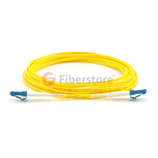
The LC connector patch cable have LC to LC, LC to MT-RJ, LC to SC, LC ST fiber patch cable .  The LC fiber optic patch cable is with a small form factor (SFF) connector and is ideal for high density applications. The LC fiber patch connector has a zirconia ceramic ferrule measuring 1.25mm O.D. with either a PC or APC end face, and provides optimum insertion and return loss. The LC fiber patch cable connector is used on small diameter mini-cordage (1.6mm/2.0mm) as well as 3.0mm cable. LC fiber cable connectors are available in cable assembled or one piece connectors. The LC fiber optic assemblies family is Telcordia, ANSI/EIA/TIA and IEC compliant.

lc fiber optic patch cable

We offer LC fiber cables and LC fiber patch, including single mode 9/125 and multimode 50/125, multimode 62.5/125, LC-LC, LC-SC, LC-ST, LC-MU, LC-MTRJ, LC-MPO, LC-MTP, LC-FC, OM1, OM2, OM3. Other types also available for custom design. Excellent quality and fast delivery.

Talk about LC connector, the common connector type we have seen, there are FC connector, SC connector, ST connector, ect. The following is some connector type features.

FC: A metal screw on connector, with a 2.5mm ferrule, developed by NTT. The ruggedness of this connector leads to its extensive use at the interfaces of test equipment. It is also the most common connector used for PM, polarization maintaining, connections. Please note that there are currently four different specifications for the key width on FC connectors and for the slot width on FC adapters. Therefore not all FC connectors will fit into all FC adapters.

LC: As mall form factor plastic push/pull connector, with a 1.25mm ferrule, developed by Lucent. The LC has been referred to as a miniature SC Connector. It is mainly used in the United States.

MTP: A push/pull ribbon connector, which holds up to 12 fibers. The 12-fiber capacity allows for very dense packing of fibers and a reduction in the number of connectors required.

SC: A plastic push-pull connector, with a 2.5mm ferrule, developed by NTT. Push-pull connectors require less space in patch panels than screw on connectors. The SC is the second most commonly used connector for PM, polarization maintaining, connections.

ST: A metal bayonet coupled connector, with a 2.5mm ferrule, developed by AT&T. The ferrule moves as load is applied to the cable in this aging design. There is a version of the ST, which the Navy uses extensively, where the ferrule does not move as a load is applied to the cable.

Fiberstore has a global reputation for bringing best-in-class technology and design concepts to the marketplace. Added to close customer relationships, decades of experience in the industry and outstanding service and support, make Fiberstore the right choice for fiber optic components and systems that will splice your fiber optic components together. We offer fiber optic patch cable, fiber optic cable, fiber optic transceivers, ect. In particular, Fiberstore products include optical subsystems used in fiber-to-the-premise, or FTTP, deployments which many telecommunication service providers are using to deliver video, voice, and data services.

Related Article:  Which Patch Cable Should I Choose for My Optical Transceiver?

Connectorized Couplings

Share

Quite often it is desirable to have a means of connecting two fibers together through a temporary mating device or connector. Figure 7.4 shows a common way to implement such a connector. Each fiber is placed in a ferrule whose function is to provide the mechanical support for the fiber and hold it in place tightly. The ferrule can be made out of plastic, metal, or ceramic materials. The central piece of the connector itself is an alignment sleeve. The two ferrules are inserted in the sleeve, and proper alignment between the cores is ensured because of the tight mechanical tolerances of the ferrules and the sleeve. The gap between the two fibers can be controlled by a mechanical stop which determines the exact stopping positions of the fibers. In some variations, the alignment sleeve is tapered to improve connector mating and demating.

Well-designed connectors provide low coupling loss, in the order of 0.1 dB or less. However, as shown in Fig. 7.5, a number of underirable situations can reduce the coupling efficiency. Figure 7.5a shows a case of two fibers with different core diameters. In general, whenver the numberical apertures of two fibers are different, the potential for power loss exists. In this case, light coupling from a narrower fiber core to a wide fiber core is easier and more efficient compared to coupling in the other direction. Figure 7.5b shows an example of poor concentricity. Fibers that do not provide a tigh concentricity tolerance may show large coupling variations depending on the orientation or from one pair of fibers to the next.

fiber connector

A large air gap, shown in Fig 7.5c, is another reason for loss of power. An air gap can result from incomplete insertion of the fiber or from mechanical problems inside the sleeve. It is also common for microscopic dust particles to get into fiber optic connector, preventing them from making proper conatact, or even scratching and damaging the fiber facets.

More dramatic power reduction results when dust particles land on the fiber core, blocking the light path. As a result, constant monitoring and cleaning of fiber facets are important to prevent such probems. Angular or lateral displacement, the mechanical tolerances are not tigh enough or when the dimensions of the sleeve and the ferrule do not match.

A fiber connector is characterized by several important parameters. As noted before, the most important factor is insertion loss, or simply connector loss. Another important factor is repeatability. If the same two fibers are connected through the same connector a number of times, each time the coupling will be slightly different. A good connector assmbly provides a small standard deviation for coupling efficiency across multiple insertions. Another desiralbe specification of a fiber connector is low return loss, i.e., a low back reflection. Return loss is defined as the ratio of the reflected power from the connector to the input power. For example, a return loss f 30 dB means 0.001 of the input power is reflected back from the connector. A conector must also be resistant and show a minimal coupling variation in the presence of normal mechanical forces such as axial and lateral forces. This is a practical requirement because in a normal environment it is likely for the connector to encounter a range of mechanical forces.

A wide range of connectors have been designed and are in use in the industry. Here we give an overview of some of the most popular types.

Straight tip or ST connectors are one of the more common type of connectors and in wide use in many applications. The ferrule diameter in an ST connector is 2.5 mm. ST connectors are spring loaded and enaged by a twist-and-lock mechanism.

Fixed connector or FC connectors use an alignment key and a threaded (screw-on) socket and are similar to the popular SMA connectors used in electronics. They are in wide use in single-mode applications and provide low insertion loss and high repeatability.

Subscriber connector, or SC, is another common type of connector. The advantage of SC connectors is that they are engaged by a push-and-snap mechanism, without the need for any roation. This make plugging and unplugging them very easy and also reduces wear out. Moreover, a higher connector density is achieved. Many transceivers provide either an SC receptacle connector, or a pigtail SC connector, as their optical interface. The push-and-snap feature of SC connectors thus provides very convenient and easy way of connecting to optical trasceivers. SC connectors are avaiable in simplex and duplex variations. The ferrule diameter in an SC connector is 2.5 mm.

SC fiber optic patch cable is one of the earliest stype and one of the most commonly used fiber optic cable, it is convenient to use and cost saving, SC fiber optic patch cord is widely uesed in fiber optic networks. SC fiber patch cable is with zirconia sleeve and plastic housing. The common type of SC connector patch cord, there are SC to SC fiber patch cord,  SC to LC Fiber Optic Patch Cable, SC to ST Fiber Optic Patch Cable,  SC to FC Fiber Optic Patch Cable, ect.

The LC or small form factor connector is similar to the SC, but with half the size. The diameter of the ferrule in an LC connector is 1.25 mm, vs 2.5 mm for most other connectors. This allow for twice the connector density for a given space. Because of their compactness, LC connectors have become more popular and are used in many high-end transceivers such as SFPs and XFPs.  LC fiber optic patch cable is with a small form factor (SFF) connector and is ideal for high density applications. LC fiber optic patch cord connector has a zirconia ceramic ferrule measuring 1.25mm O.D. with a PC or APC endface, and provides optimum insertion and return loss.

Related Article:  Which Patch Cable Should I Choose for My Optical Transceiver?

Two Main Connector Type: ST vs SC

Share

There are many different fiber optic connection methods, connector types, and ways to terminate them, such as SC connector and ST connector. Single-mode and multi-mode connectors create differences in the types and methods used as well. If you plan to work with fiber optics, you should perform in-depth research about fiber before attempting to terminate it. In fact, it is best to take a course in fiber optic cable termination or learn from an expert. This post will tell you how to choose  ST vs SC connector when terminating fiber and adding connectors.

In addition to the two main connector types of ST vs SC connector, there are many other connection types that have been developed through the years. But to limit the scope of this book to what is most widely used on data networks today, you need to be thoroughly familiar with the ST vs SC connectors.

ST vs SC Connector: Which to choose?

SC Connector

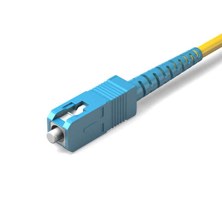
SC type connector is a snap-in connector, meaning that you place it in a receptacle, such as on a network switch, and click it into place; this is also called stick and click. The SC connector is shown in the figure below.

SC connector

SC connector is a relatively new connector-type technology, but are in popular use today. Part of their popularity is that SC connector is cheaper and easier to use than ST connectors, and less prone to damage. You will most likely see these types of connections from large core switches with fiber uplinks to smaller closet switches in campus network.

As we know, SC patch cable is with SC fiber connector which was invented by NTT. It is widely used fiber optic patch cables. SC fiber optic patch cable has low cost and good durability, SC fiber optic patch cables is with a locking tab on the cable termination, it is a push and pull type optical connector. The common SC patch cable we have seen, there are SC to FC, SC fiber optic cable, SC to ST, and SC to LC.

ST Connector

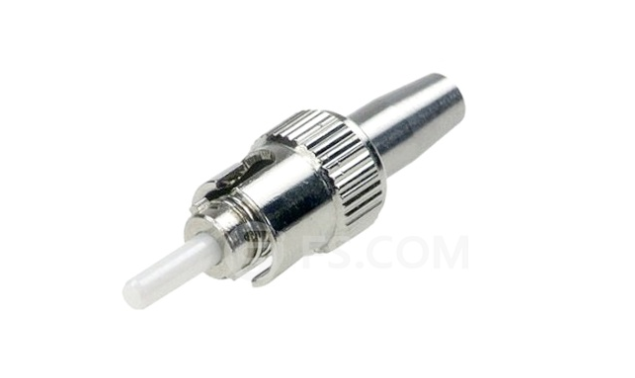
ST connector is another type of fiber connection. Like the BNC connector for coaxial cable, it has a bayonetbased mounting end and a long cylindrical ferrule, which is spring-loaded sheath used to hold the fiber in place. You insert the connector into a receptacle and twist it to lock it into place. Stick and twist considered an older technology, but is still widely used on data networks, and its install base is broad. An ST connector is shown in the figure below.

st-connector

Real-world production environments (especially when working with Cisco Systems, Nortel Networks) do not include ST in new implementations. In most cases, the only way to use this order technology is with a mediation device, such as a transceiver, which has one end that plugs into an attachment unit interface (AUI) port and an ST-based mounting connection on the other end.

Conclusion on ST vs SC Connector

To facilitate installation of our active fiber equipment, we support a large selection of fiber optic patch cords. The always in stock fiber cables are with SC connector, ST connector, LC connector and FC connector type, simplex and duplex. Our patch cords range from 0.5m to 10m and have almost all available combination of optical connectors. The most available lengths are 1m, 2m, 3m, 5m, and 10m patch cords. All single-mode patch cords are UPC polished (Ultra Physical Contact), while the multi-mode cables are PC polished. All fiber patch cords are manually tested and verified and each patch cable is individually sealed and labeled with measured optical performance.We offer competitive price for fiber optic patch cable, our company has strictly quality control system and high quality products,the custom fiber patch cable is fast delivery to worldwide customers.

Related Article:  Which Patch Cable Should I Choose for My Optical Transceiver?

                             How Many Fiber Connector Types Do You Know?

                             How Much Do You Know About Fiber Connector Cleaning? 


Overview of 16 Gbps Fiber Channels

Share

Offering considerable improvements from previous FC speeds, 16 Gbps FC uses 64b/66b encoding, retimers in modules, and transmitter training. Doubling the throughput of 8 Gbps to 1,600 Mbps, it uses 64b/66b encoding to increase the efficiency of the link. 16 Gbps FC links also use retimers in the optical modules to improve link performance characteristics, and electronic dispersion compensation and transmitter training to improve backplane links. The combination of these technologies enables the 16 Gbps FC to provide some of the highest throughput density in the industry, making data transfers smoother, quicker, and cost-efficient.

Although 16 Gbps FC doubles the throughput of 8 Gbps FC to 1600MBps, the line rate of the signals only increases to 14.025 Gbps because of a more efficient encoding scheme. Like 10 Gbps FC and 10 Gigabit Ethernet (GbE), 16 Gbps FC uses 64b/66b encoding, that is 97% efficient, compared to 8b/10b encoding, that is only 80% efficient. If 8b/10b encoding was used for 16 Gbps FC, the line rate would have been 17 Gbps and the quality of links would be a significant challenge because of higher distortion and attenuation at higher speeds. By using 64b/66b encoding, 16 Gbps FC improves the performance of the link with minimal increase in cost.

To remain backward compatible with previous Fiber Channel speeds, the Fiber Channel application specific integrated circuit (ASIC) must support both 8b/10b encoders and 64b/66b encoders.

As seen in Figure 2-1, a Fiber Channel ASIC that is connected to an SFP+ module has a coupler that connects to each encoder. The speed-dependent switch directs the data stream toward the appropriate encoder depending on the selected speed. During speed negotiation, the two ends of the link determine the highest supported speed that both ports support.

The second technique that 16 Gbps FC uses to improve link performance is the use of retimers or Clock and Data Recovery (CDR) circuitry in the SFP+ modules. The most significant challenge of standardizing a high-speed serial link is developing a link budget that manages the jitter of a link. Jitter is the variation in the bit width of a signal due to various factors, and retimers elliminate most of the jitter in a link. By placing a retimer in the optical modules, link characteristics are improved so that the links can be extended for optical fiber distances of 100 meters on OM3 fiber. The cost and size of retimers has decreased significantly so that they can now be intergrated into the modules for minimal cost.

The 16 Gbps FC multimode links were designed to meet the distance requirements of the majority of data centers. Table 2-2 shows the supported link distances over multimode and single-mode fiber 16 Gbps FC was optimized for OM3 fiber and supports 100 meters. With the standardization of OM4 fiber, Fiber Channel has standardized the supported link distances over OM4 fiber, and 16 Gbps FC can support 125 meters. If a 16 Gbps FC link needs to go farther than these distances, a single-mode link can be used that supports distances up to 10 kilometers. This wide range of supported link distances enables 16 Gbps FC to work in a wide range of environments.

Another important feature of 16 Gbps FC is that it uses transmitter training for backplane links. Transmitter training is an interactive process between the electrical transmitter and receiver that tunes lanes for optimal performance. The 16 Gbps FC references the IEEE standards for 10GBASE-KR, which is known as Backplane Ethernet, for the fundamental technology to increase lane performance. The main difference between the two standards is that 16 Gbps FC backplanes run 40% faster than 10GBASE-KR backplanes for increased performance.

Fiberstore introduces it’s new OM4 Laser-Optimized Multimode Fiber (LOMMF) “Aqua” cables, for use with 40/100Gb Ethernet applications. These new technology, 50/125um, LC/LC Fiber Optic cables, provide nearly three times the bandwidth over conventional 62.5um multimode fiber, with performance rivaling that of Singlemode cable, at a much reduced cost. LOMMF cable allows 40/100Gb serial transmission over extended distances in the 850nm wavelength window, where low-cost Vertical Cavity Surface Emitting Lasers (VCSELs) enable a cost-effective, high-bandwidth solution. OM4 fiber optic patch cord is ideally suited for LAN’s, SAN’s, and high-speed parallel interconnects for head-ends, central offices, and data centers. Tripp Lite warrants this product to be free from defects in material and workmanship for Life. Now the following is the OM4 fiber from Fiberstore.

OM4 SC to SC fiber patch cord feature an extremely high bandwidth–4700MHz*km, more than any other mode. They support 10GB to 550 meters and 100GB to 125 meters. These cables are suitable for high-throughput applications, such as data storage. These cables are fully (backwards) compatible with 50/125 equipment as well as with 10 gigabit Ethernet applications. These connectors utilize a UPC (Ultra Physical Contact) polish which provides a better surface finish with less back reflection. With the OM4 cables, you can use longer lengths than OM3 cables while still having an excellent connection.

We offer a huge selection of single and multimode patch cords for multiple applications: mechanical use, short in-office runs, or longer runs between and within buildings, or even underground. Gel-free options are available for less mess, and Bend Insensitive cables for minimizing bend loss, which can be difficult to locate and resolve.

Related Article:  Which Patch Cable Should I Choose for My Optical Transceiver?

Small Form Factor Fiber-Optic Connectors

Share

One of the more popular styles of fiber-optic connectors is the small form factor (SFF) style of connector. SFF connectors allow more fiber optic terminations in the same amount of space over their standard-sized counterparts. The two most popular are the mechanical transfer registered jack (MT-RJ or MTRJ), designed by AMP, and the Local Connector (LC), designed by Lucent.

MT-RJ

The MT-RJ fiber optic connector was the first small form factor fiber optic connector to see widespread use. It is one-third the size of the SC and ST connectors it msot often replaces. It had the following benefits:

● Small size
● TX and RX strands in one connector
● Keyed for single polarity
● Pre-terminated ends that require no polishing or epoxy
● Easy to use

LC

Local Connector is a newer style of SFF fiber optic connector that is overtaking MT-RJ as fiber optic connector. It is especially popular for use which Fiber Channel adapters and Gigabit Ethernet adapters. It has similar advantages to MT-RJ and other SFF-type connectors but is easier to terminate. It uses a ceramic insert as standard-sized fiber-optic connectors do. Figure 1.21 shows an example of the LC connector. Mentioned fiber optic connector, we know fiber optic patch cords, a fiber optic patch cord is constructed from a core with a high refractive index, surrounded by a coating with a low refractive index that is surrounded by a protective jacket. Transparency of the core permits transmission of optic signals with little loss over great distances. The coating’s low refractive index reflects light back into the core, minimizing signal loss. The protective jacket minimizes physical damage to the core and coating.

Connector design standards include FC, SC, ST, LC, MTRJ, MPO, MU, SMA, FDDI, E2000, DIN4, and D4. Cables are classified by the connectors on either end of the cable; some of the most common cable configurations include FC-FC, FC-SC, FC-LC, FC-ST, SC-SC, and SC-ST.

lc to lc fiber patch cord is used to send high-speed data transmissions throughout your network. LC/LC fiber optic cables connect two components with fiber optic connectors. A light signal is transmitted so there is no outside electrical interference. Our LC/LC fiber optic patch cables are 100% optically tested for maximum performance. We have all lengths and connectors available.

Multimode LC/LC fiber optic patch cable send multiple light signals. They are 62.5/125µ. Common connectors are ST, LC, SC and MTRJ. Our 62.5/125µ LC/LC multi-mode fiber cables can support gigabit ethernet over distances up to 275 meters.

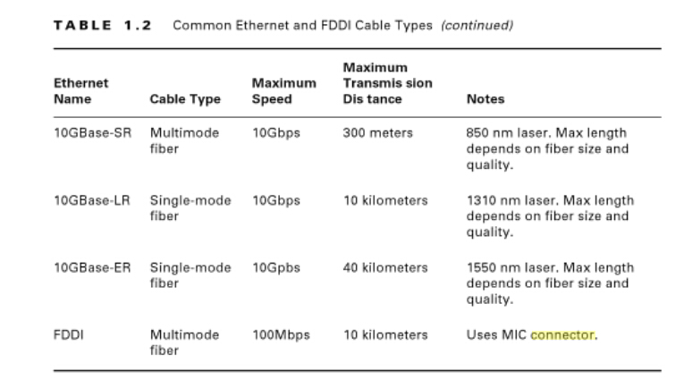
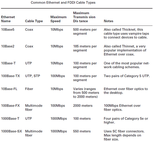
Cable Type Summary

common-ethernet

Fiber optic patch cables are used for linking the equipment and components ,we have fiber optic patch cable with different fiber connector types,our low insertion loss and low back reflection .Axen Technologies fiber patch cable is widely applied in Telecommunication Networks ,Gigabit Ethernet and Premise Installations.

Related Article:  Which Patch Cable Should I Choose for My Optical Transceiver?