Tag Archives: fiber optic patch cord

Overview of 16 Gbps Fiber Channels

Share

Offering considerable improvements from previous FC speeds, 16 Gbps FC uses 64b/66b encoding, retimers in modules, and transmitter training. Doubling the throughput of 8 Gbps to 1,600 Mbps, it uses 64b/66b encoding to increase the efficiency of the link. 16 Gbps FC links also use retimers in the optical modules to improve link performance characteristics, and electronic dispersion compensation and transmitter training to improve backplane links. The combination of these technologies enables the 16 Gbps FC to provide some of the highest throughput density in the industry, making data transfers smoother, quicker, and cost-efficient.

Although 16 Gbps FC doubles the throughput of 8 Gbps FC to 1600MBps, the line rate of the signals only increases to 14.025 Gbps because of a more efficient encoding scheme. Like 10 Gbps FC and 10 Gigabit Ethernet (GbE), 16 Gbps FC uses 64b/66b encoding, that is 97% efficient, compared to 8b/10b encoding, that is only 80% efficient. If 8b/10b encoding was used for 16 Gbps FC, the line rate would have been 17 Gbps and the quality of links would be a significant challenge because of higher distortion and attenuation at higher speeds. By using 64b/66b encoding, 16 Gbps FC improves the performance of the link with minimal increase in cost.

To remain backward compatible with previous Fiber Channel speeds, the Fiber Channel application specific integrated circuit (ASIC) must support both 8b/10b encoders and 64b/66b encoders.

As seen in Figure 2-1, a Fiber Channel ASIC that is connected to an SFP+ module has a coupler that connects to each encoder. The speed-dependent switch directs the data stream toward the appropriate encoder depending on the selected speed. During speed negotiation, the two ends of the link determine the highest supported speed that both ports support.

The second technique that 16 Gbps FC uses to improve link performance is the use of retimers or Clock and Data Recovery (CDR) circuitry in the SFP+ modules. The most significant challenge of standardizing a high-speed serial link is developing a link budget that manages the jitter of a link. Jitter is the variation in the bit width of a signal due to various factors, and retimers elliminate most of the jitter in a link. By placing a retimer in the optical modules, link characteristics are improved so that the links can be extended for optical fiber distances of 100 meters on OM3 fiber. The cost and size of retimers has decreased significantly so that they can now be intergrated into the modules for minimal cost.

The 16 Gbps FC multimode links were designed to meet the distance requirements of the majority of data centers. Table 2-2 shows the supported link distances over multimode and single-mode fiber 16 Gbps FC was optimized for OM3 fiber and supports 100 meters. With the standardization of OM4 fiber, Fiber Channel has standardized the supported link distances over OM4 fiber, and 16 Gbps FC can support 125 meters. If a 16 Gbps FC link needs to go farther than these distances, a single-mode link can be used that supports distances up to 10 kilometers. This wide range of supported link distances enables 16 Gbps FC to work in a wide range of environments.

Another important feature of 16 Gbps FC is that it uses transmitter training for backplane links. Transmitter training is an interactive process between the electrical transmitter and receiver that tunes lanes for optimal performance. The 16 Gbps FC references the IEEE standards for 10GBASE-KR, which is known as Backplane Ethernet, for the fundamental technology to increase lane performance. The main difference between the two standards is that 16 Gbps FC backplanes run 40% faster than 10GBASE-KR backplanes for increased performance.

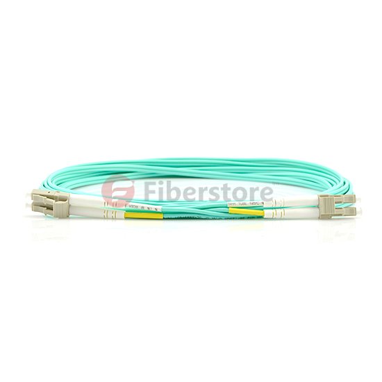
Fiberstore introduces it’s new OM4 Laser-Optimized Multimode Fiber (LOMMF) “Aqua” cables, for use with 40/100Gb Ethernet applications. These new technology, 50/125um, LC/LC Fiber Optic cables, provide nearly three times the bandwidth over conventional 62.5um multimode fiber, with performance rivaling that of Singlemode cable, at a much reduced cost. LOMMF cable allows 40/100Gb serial transmission over extended distances in the 850nm wavelength window, where low-cost Vertical Cavity Surface Emitting Lasers (VCSELs) enable a cost-effective, high-bandwidth solution. OM4 fiber optic patch cord is ideally suited for LAN’s, SAN’s, and high-speed parallel interconnects for head-ends, central offices, and data centers. Tripp Lite warrants this product to be free from defects in material and workmanship for Life. Now the following is the OM4 fiber from Fiberstore.

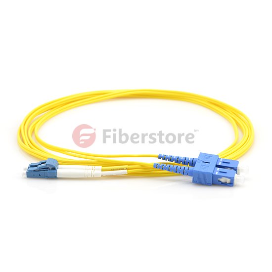
OM4 SC to SC fiber patch cord feature an extremely high bandwidth–4700MHz*km, more than any other mode. They support 10GB to 550 meters and 100GB to 125 meters. These cables are suitable for high-throughput applications, such as data storage. These cables are fully (backwards) compatible with 50/125 equipment as well as with 10 gigabit Ethernet applications. These connectors utilize a UPC (Ultra Physical Contact) polish which provides a better surface finish with less back reflection. With the OM4 cables, you can use longer lengths than OM3 cables while still having an excellent connection.

We offer a huge selection of single and multimode patch cords for multiple applications: mechanical use, short in-office runs, or longer runs between and within buildings, or even underground. Gel-free options are available for less mess, and Bend Insensitive cables for minimizing bend loss, which can be difficult to locate and resolve.

Related Article:  Which Patch Cable Should I Choose for My Optical Transceiver?

The Fiber Optic Patch Cord Reliability

Share

Fiber optic patch cords are one of the simplest elements in any optical network, consisting of a piece of fiber optic cable with a connector on each end. Despite its simplicity, the Fiber Optic Patch Cord can have a strong effect on the overall performance of the network. The majority of problems in any network occur at the physical layer and many are related to the patch cord quality, reliability, and performance. Therefore, using patch cords that are more reliable helps reduce the chance of costly network downtime. This article mainy the patch cord reliability.

Network designers would prefer components with a history of proven long-term performance. However, since optical networking is a relatively new technology, there is no significant long-term data for many components. Therefore, designers must rely upon testing from the component manufacturer or supplier that can simulate this history and assure the quality and reliability over the life of the network. This paper discusses the importance of quality, reliability, and performance as they relate to industry standards and manufacturing practices. The performance of the patch cord is also studied using a “perfect patch cord” and polishing observations as tools to understand patch cord principles.

Patch cord reliability is guaranteed not only by using quality components and manufacturing processes and equipment, but also by adherence to a successful Quality Assurance program. While patch cords themselves are typically tested 100% for insertion loss and return loss, if applicable, there are many other factors that need to be monitored to insure the quality of the patch cord.

One of the most important factors is the epoxy. Epoxies typically have a limited shelf life and working life, or “pot life.” This information is readily available from the manufacturer. It is absolutely necessary that both of these criteria be verified and maintained during manufacture. Epoxy beyond its expiration date needs to be discarded. Chemical changes affecting the cured properties of the epoxy can occur after this date. This date can also be dependent on storage conditions, which need to be observed.

Most epoxies used in fiber optic terminations are two-part epoxies and, while they cure at elevated temperatures, preliminary cross-linking will begin upon mixing. Once this has started, the viscosity of the epoxy can begin to change, making application more difficult over time. The epoxy can become too thick to fill the ferrule properly and too viscous to enable a fiber to penetrate, causing fiber breakage.

Many of the tooling used in patch cord assembly also has periodic maintenance and a limited tool life. This includes all stripping, cleaving and crimping tools. Most stripping tools, whether they are hand tools or automated machines, can be damaged by the components of the cable, most notably the aramid yarn strength members. Buffer strippers will dull with prolonged usage, increasing the likelihood that they will not cleanly cut the buffer. This can lead to overstressing the fiber when the buffer is pulled off. When a cleaving tool wears out and a clean score is not made, it is almost impossible to detect during manufacturing. However, the result could be non-uniform fiber breakage during the cleave, which can result in either breaking or cracking the fiber below the ferrule endface. In this instance, the connector will have to be scrapped. Even crimp tools require periodic maintenance to insure the proper forces and dimensions are consistent. Crimp dies also have a tendency to accrue epoxy build-up, which can affect the crimping dimensions and potentially damage the connector.

The integrity of the incoming materials and manufacturing processes, once specified, needs to be adhered to all the appropriate guidelines and procedures. The importance of these materials not only has a strong influence on product reliability, but also on product performance.

Fiber optic patch cords are fiber optic cables used to attach one device to another for signal routing. It compresses in the entire electric network plank and room that wall plank and the flexibility cabinet needs, causes such the person who passes room merely considerably traditional FC,LC,ST and SC’s connection box in parts.Intelligently the bright and beautiful corporation adopts well-developed technique and installation, and carrying on scale manufacture, the produce performance is good, and the quality is steady dependable. Fiberstore manufactures fiber optic patch cables, fiber optic patch cords, and pigtails. There are LC, SC, ST, FC, E2000, SC/APC, E2000/APC, MU, VF45, MT-RJ, MPO/MTP, FC/APC, ST/APC, LC/APC, E2000, DIN, D4, SMA, Escon, FDDI, RoHS compliant, LSZH, Riser,Plenum, OFNR, OFNP, simplex, duplex, single mode, 9/125, SM, multimode, MM, 50/125, 62.5/125; armored fiber optic patch cords, OM4 patch cord, waterproof fiber optic patch cords, ribbon fiber optic cables and bunched fiber optic cables.

Related Article:  Which Patch Cable Should I Choose for My Optical Transceiver?

Brief Introduction to Fiber Optic Patch Cords

Share

Fiber optic patch cord is the simplest fiber optic elements, consisting of a short length of optical fiber with a connector on either end. Since they are used to connect various components and instruments in a fiber optic system, their characteristics in terms of loss and aging determine the overall performance of the system. In principle, when two patch cords are connected, if the fibers are identical, it should result in almost zero loss. In actual practice the loss may not be very small since the fiber may not be completely concentric with the connector center, there could be dust at the tip of the connector, or there could be misalignments when two patch cords are mated. Fiber optic patch cord with different types of fibers and different connector types are available. The typical insertion loss of patch cords is about 0.4 dB, with a return loss of better than 50 dB.

We mustn’t forget the role that optical patch cords play in the practical use of an optical cable system. A patch cord is a short length of a simple optical cable, typically one to five meters, that is used to connect the active or final equipment into the cable plant, usually by way of the patch panel.

The patch cord can be of a single fiber, simplex, or two fibers, duplex. If it is duplex then the convention is to cross the circuit so that A goes to B and B to A, as seen in Figure 1.

Talk about simplex and duplex, we can recommend you some patch cord from our store.

LC-LC Duplex 10G OM4 50/125 Multimode Fiber Optic Patch Cord

lc lc fiber optic patch cord

Cost-effective solution that provides higher bandwidth and transmission rates and supports longer distances with lower loss than 62.5 fiber. Specifically designed for use with today’s narrower aperture components, this LC-LC fiber optic cable is fully compatible with multimode applications. The patented injection molding process provides each connection greater durability in resisting pulls, strains, and impacts from cabling install.

LC-SC Duplex 9/125 Single-mode Fiber Optic Patch Cord

lc sc fiber optic patch cord

● LC-SC Connectors
● Singlemode Duplex fiber optic cable
● Micron: 9/125um
● Complete with Lucent Technologies aqua jacket
● Bandwidth transmitting rates up to 10 gigabits
● All of our fiber optic patch cables feature the high degree connectors
● 100% optically tested to ensure high performance
● Color: Yellow

SC fiber cable is one of the earliest types and one of the most commonly used fiber optic cable, it is convenient to use and cost saving – It is the cheapest type fiber optic cable. SC fiber patch is widely used in fiber optic networks. SC fiber patch cable is with zirconia sleeve and plastic housing.

The patch cord must incorporate exactly the same fiber as is contained within the rest of the cable plant. There is no reason why the connectors on each end need to be the same. What is important is that one end of the patch cord matches that found on the active equipment and the other end matches the patch panel.

Patch Cord Optical Power Loss Measurement

Share

Measurement of fiber optic cable loss is an established practice that has been performed for many years. However, over time, the performance of fiber optic equipment has been improved, so occasionally it is useful to perform a practical re-assessment of the accuracy of these measurements.

Multi-mode patch cord optical loss power measurement is performed using the steps described in ANSI/TIA-526-14, method A. The fiber optic patch cord is substituted for the cable plant. Because patch cords are typically no longer than 5 m, the loss for the optical fiber is negligible and testing can be performed at 850 nm or 1300 nm. The loss measured in this test is the loss for the patch cords connector pair. ANSI/TIA-568-C.3 states that the maximum loss for a connector pair is 0.75 dB.

After setting up the test equipment as described in ANSI/TIA-526-14, method A, clean and inspect the connectors at the ends of the patch cords to be tested. Verity that your test jumpers have the same optical fiber type and connectors as the patch cords you are going to test. The transmit jumper should have a mandrel wrap or modal conditioner depending on the revision ANSI/TIA-526-14 being used for testing. Ensure that there are no sharp bends in the test jumpers or patch cord during testing.

Because both patch cord connectors are easily accessible, optical power loss should be measured in both directions. The loss for the patch cord is the average of the two measurements. If the loww for the patch cord exceeds 0.75dB in either direction, the patch cord needs to be repaired or replaced.

For testing the loss of a patchcord, you only need an 850 nm LED light source for multimode cable or 1310 laser for singlemode, a fiber optic power meter and some reference patchcords. Just remember that the patchcords used for references in testing must be good for tests to be valid, so you test them as you would other patchcords, just more often.

Testing patch cords is similar to testing any fiber optic cable. Use one reference patch cord to set a 0 dB reference. Connect a patch cord to test to the reference patch cord with a mating adapter. Connect the power meter to the other end of the patch cord and measure the loss. Since the length of the fiber is short, the loss contribution of the fiber is ignoble. And since one end of the cable is attached to the power meter, not another cable, you only measure the loss of the one connection between the reference cable and the cable under test, so you can test each connector individually.

To complete the testing of the patch cord, reverse the cable you are testing to check the connector on the other end. Sometimes you will find one bad connector and can replace it to make the patch cord useful again. But often the cost of replacing the connector may be higher than replacing the patch cord itself.

If your test equipment has different connectors than the patchcords you are testing, you will need hybrid reference cables with connectors compatible with the equipment on one end and the patchcord connectors on the other end. You will also need the correct connector adapters for your power meter.

Obviously, all reference cables used for testing must have high quality connectors to get reliable test results. Use this same method to test your reference cables against each other and discard any with high losses, usually those with losses over 0.5 dB.