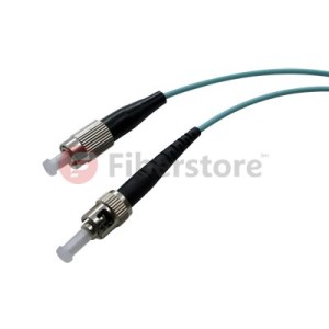
Tag Archives: fiber optic patch cables

Data Center Patch Cords Organized

Share

The benefit of having neat and organized cabling obviously applies to patch cords as much as structured cabling. When you go beyond green considerations, it can be argued that it’s more important to have neat patch cords than structured cabling. Data Center users typically interact with a patching field when installing or servicing hardware rather than structured cabling. Patching fields can be more challenging to maintain in some server environments, however, due to frequent hardware changes and sometimes minimal management of how patches are run.

You can follow several strategies to keep Data Center patch cords organized, thereby improving airflow to equipment, reducing energy consumption of your cooling infrastructure, and easing troubleshooting. (Not to mention maintaining the professional appearance of your Data Center.)

■ Employ a distributed cabling hierarchy: Already mentioned as beneficial for structured cabling, this approach can help with Fiber Optic Patch Cables as well. Having Data Center networking patch fields divided into smaller segments around the Data Center mitigates cabling density and potentially improves airflow to the associated networking equipment.
■ Right-size port counts: Planning the correct number of ports in your Data Center – and reserving space for future expansion of patch fields – helps avoid messy cabling. Installing too many ports can result in unnecessarily large cable bundles; installing too few can trigger picemeal cabling additions in the future that fit awkwardly with the original cabling infrastructure.
■ Use ample wire management: However many connections you install in your network patching fields, be sure to include sufficient vertical and horizontal wire management to handle the maximum quantity of patch cords you plan for. This is of particular importance for some Category 6A patch cords because of their increased outsied cable diameters and soild copper core wire construction. This type of cord promotes a cable memory that can be increasingly difficult to manage as the number of patch cords multiply.
■ Prepatch networking connections: Hardware density in modern Data Centers can involve thousands of cable connections in a single server row. Prepatching networking devices and patch fields all together, before servers are installed, helps ensure that cabling is routed neatly.
■ Provide patch cords in different length – and use them: Stock commonly used types of patch cords in your Data Center in multiple lengths so that whoeer install your hardware can make a neat connection between devices and patching fields. That means correctly routing cabling through the available wire management rather than making a straight-line connection that blocks access to hardware or patch panels. It also means choosing the right length of cable length, so there is no slack to be either coiled up and hidden in the wire management system or left hanging at the end of a connection.

Implementing these cabling practices, first when designing a new Data Center and then when operating, doesn’t just make the facility greener by improving airlow and conserving cabling material, it also makes it easier to use and less prone to accidental down-time.

Fiberstore manufactures and stocks fiber optic patch cables. Our stock cables feature FC/PC, FC/APC, and SMA connectors, and use single mode (SM), polarization-maintaining (PM), or multimode (MM) fiber. Buy LC fiber  optic cable series, same day shipping to your countyre now. We offer ar-coated cables for fiber-to-free space use, lightweight cables for optogenetics, high-power cables, and many other specialty fiber patch cables from stock. We also offer multimode fiber bundles, as well as custom patch cables with 24 hour turnaround on many orders. If you do not see a stock cable that is suitable for your application, please contact us.

Related Article:  Which Patch Cable Should I Choose for My Optical Transceiver?

The Development of Multimode Fiber Patch Cable

Share

Corning and Lucent and other large companies proposed a “new generation of multi-mode fiber” concept to the international standardization bodies. A new generation of multimode fiber patch cable standards drafted by the International Organization for Standardization / International Electrotechnical Commission (ISO / IEC) and the Telecommunications Industry Alliance (TIA-TR42). As a new generation of multimode fiber transmission medium 10Gb / s Ethernet, be included in IEEE 10Git / s Ethernet standard. This article will briefly describe the new generation of multimode fiber patch cable critical technology.

1.1 The Typle of Multimode Fiber Patch Cable

The new generation of multimode fiber patch cable is 50/125μm, graded-index multimode fiber distribution. The number of this transmission mode Fiber Optic Cables is approximately 62.5μm multimode fiber transmission mode 1/2.5. This can effectively reduce the dispersion of the multimode fiber mode, increase the bandwidth. For 850nm wavelength, 50/125μm Multimode fiber bandwidth is 500MHz.km. Recent experiments confirmed: the use of 850nm vertical cavity surface emitting laser (VCSEL) as a light source in the 1Gb / s rate, 50μm multimode fiber core diameter standard error can be no transfer 1750m, 50μm core diameter multimode fiber can be a new generation of error-free transmission 2000m. In the 10Gb / s down, 50μm core diameter multimode fiber can transmit a new generation of 600m. A new generation of multi-mode fiber is mainly used to support high-speed Ethernet (Ethernet), Fibre Channel (FC) and fiber optic interconnection (OIF). Meanwhile at 10Gbit / s system can transmit 600m, so that it can be used for building backbone and campus backbone extraordinary distance from the middle. In the data center design, within a distance of 100m to support higher speed (40G and 100Gbits / s? Ethernet, 16G and 32Gbits / s Fibre Channel) data transmission requirements.

The related products about New Generation multimode mode fiber patch cable, SMA905-ST Duplex 50/125 Dia2.5mm OM2 multimode fiber patch cable from fs.com, the products picture is below:
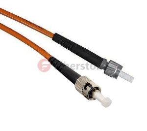
OM2 Multimode Fiber

The SMA-905 fiber optic patch cord, also known as FSMA connector, was one of the First fiber optic interconnect system that gained industry wide acceptance.SMA905 fiber patch cords make use of threaded connections and is still widely used for military, industrial, medical and Surgical applications and laser systems because of their low cost multimode coupling. It features simple termination and Assembly, and is TIA and IEC compliant. SMA 905 multimode connectors are available with stainless alloy or stainless steel ferrules.

1.2 A New Generation of Multimode Fiber Source

Traditional multimode fiber networks use light-emitting diode (LED) as light source . In low-speed network, which is an economically rational choice. However, LED is spontaneous emission light, the radiation -emitting laser is excited , the carrier lifetime is longer the former than the latter, and thus the LED modulation rate is limited , and not more than gigabit networks. Further, LED compared with a laser, the beam divergence angle, wide spectral width . After injection of multimode fiber , excite more high-order mode, the introduction of more wavelength components, so that the fiber bandwidth decreases . Fortunately 850nm vertical cavity surface emitting laser (VCSEL) not only has the advantage of these lasers, but aslo the price is basically the same with the LED. Other advantages of VCSEL are: low threshold current, may not be enlarged, driven directly by logic gates at 10Gb / s rate, get a few milliwatts of output power; emission wavelength of 850nm which does not apply to the standard single-mode fiber just for multimode fiber . At this wavelength, an inexpensive silicon detectors can be used and have a good frequency response; VCSEL another remarkable advantage is that the manufacturing process can be easily controlled distribution of the emitted light power , which is very advantageous for improving the bandwidth of MMF. It is because of these advantages, the new generation of multimode fiber standard will use 850nm VCSEL light source .

1.3 The Bandwidth Distance of Multimode Fiber Patch Cable

By comparing the above- described laser and LED , the use of multimode fiber laser light source, the transmission bandwidth should be greatly improved. However, experimental results show that simply make the bandwidth of a laser instead of LED light source, system is not only reduced but increased. IEEE Expert Group found through research, the bandwidth of multimode fiber and the optical fiber or the injection molding state of a power distribution. The preform fabrication process, the refractive index of the fiber axis prone to depression. Done before light source LED, is overfilled launch (OFL-Over Filled Launch), all of the fiber mode ( hundreds ) are excited to bring their own part of each module power. The refractive index of the fiber center delay characteristic distortion affects only a small number of models, the relatively limited impact on the modal bandwidth of the fiber. The measured multimode fiber bandwidth for the use of LED light source system is correct. However, when a laser light source, a laser beam spot is only a few microns, the divergence angle is smaller than the LED, so that only a small number of modes excited in the center of the fiber transmission, each mode carries a large part of the power, the refractive index of the fiber center distortion affect a small number of patterns of delay characteristics, so that decreased multimode fiber bandwidth. So it can not be measured with a laser light source for multimode fiber OFL bandwidth of conventional methods.

Today a new generation of multi-mode fiber main measurement bandwidth limit die by injection method (RML-Restricted Mode Launch). In this way the measured bandwidth is called ” laser -bandwidth ” or ” modal bandwidth limit “, previously done with the LED light source measured bandwidth is called “OFL bandwidth is .” Both represent the bandwidth of multimode fiber laser and LED light source with a time of injection. August 5, 2009, TIA Standards Committee released a new generation of bandwidth distance product standard multimode fiber , 850nm laser distance -bandwidth product of 470MHz.km, 850nm OFL bandwidth of distance product of 350MHz.km, 1300nm OFL bandwidth of distance plot to 500MHz.km. Incidentally, the bandwidth from the product of the above-described generation of the multi-mode fiber is only 3dB corresponding baseband bandwidth of multimode fiber, multimode fiber does not take more than a high-frequency band -pass region is also used when the transmission signal . Today, by orthogonal frequency division multiplexing (OFDM) technology , can make good use of multimode optical fiber through a high frequency band region , under conditions of use of the same fiber optic patch cable type, transmission using high frequency band signal through region greatly improved multi-mode fiber transmission capacity.

1.4 Source Injection Method

In actual use, the multimode fiber coupled laser and the following methods:

Bias injection: In order to avoid the deterioration of these lasers is injected directly into the bandwidth MMF appears, use the mode regulator
Connection (MCP Mode Conditioning Patch Cable), the laser output is coupled into a multimode fiber. Connection-mode regulator is a short Single Mode Fiber Cable, one end of which is coupled with the laser and the other end coupled to a multimode optical fiber. SMF output spot detouring from the multimode fiber axis at a distance, allowing the deviation from the range is 17 ~ 24μm, the aim is to avoid the center of the refractive index depression, but do not deviate too far, only one group is selectively lower-order mode excitation .

Centre injection: ideal for the refractive index profile, there is no central depression MMF can be used instead of the center of the injection molding
Regulator connection. The advantage of this is that the bandwidth of the laser can effectively improve the MMF to reduce the complexity of the network system and reduce system cost, a current-mode regulator 80 to the connection of approximately U.S. $ 100. Corning launched InfiniCor CL 1000 (62.5μm core diameter) and InfiniCor CL 2000 (50μm core diameter) is Gigabit Ethernet 1300nm wavelength laser directly into the mode without adjusting the first multi-connection mode fiber.

FAQ In Fiber Optic Cabling

Share

Firstly, do choose multimode or single mode fiber? What is the difference between them?

In general, the user requests the fiber transmission distance is relatively short, such as a few hundred meters, can be Multimode Fiber Optic Cable. However, if the transmission distance has several kilometers, even further, without the use of signal repeaters must be single-mode fiber.

Secondly,  Do choose 4 core, 6 core, 8 core or more core Fiber Optic Patch Cables?

Fiber complete the transfer task, it must receive at least one first serve two core. In fact, there are 4,6,8 or more optical fiber core, the core can be used as extra backup, you can do more transmission channels.

Thirdly,  Does use wall or rack-mounted fiber optic patch panel cable box?

Wall fiber boxes are generally used in small fiber-optic network, for example, a 4-core optical fiber, but if there is more number of fiber optic, it shows the advantages of rack patch panel. It can be placed inside the routers and switches with a cabinet for easy centralized management and more secure.

And then, What is the connector type of FC,SC,ST,LC,MTRJ, and Which one can be choose?

These different interfaces have used in different environments, they differ mainly in the method and shape connection, is it the same as the screws tighten or direct card? Is square or round? Large or small mouth opening (mouth relatively large place occupied by a small mouth can have greater port density)? Two heads separately or synthetic one? Users need not be too concerned about the specific interface, to note that if the extension already exists in the case of older fiber optic systems, you have to match each job.

Finally, Is the choice of the center beam tube or Stranded cable?

Central tube Fiber Optic Cable placed in the center portion of the cable core, many of the core tube synthesis bunch shape, and the outer cable surrounding two wires placed in parallel to ensure tensile strength.

The central part of Stranded cable strengthen stereotypes core fiber. Fiber core surrounded by a peripheral that strengthen the core, many cores together to form the shape layer by layer.

How to identify fiber optic, is single mode or multimode fiber?

The first is a relatively simple method for indoor fiber, it can be identified by single-mode fiber and multimode fiber external color, Single Mode Fiber Cable is yellow, Multimode Fiber Optic Cable is red. Including Fiber optic patch cords and Fiber pigtails are the same recognition.

For MPO Fiber, generally can be identified by model code, there are a bunch of characters on the cable sheath, such GYXTW-4-A1a, the last paragraph begins with A on behalf of the multi-mode fiber, beginning with B represents a multi-mode fiber, a little more detail, A1a representing 50/125 multimode fiber specifications, A1b representatives 62.5/125 multimode fiber specifications, B1.1 representatives of non-dispersion shifted single-mode fiber and so on.

If this way can not be identified single mode fiber or multimode fiber, it is only through a special device to identify, as fiber splicing machine, it will automatically recognize the single mode or multimode fiber, single mode will show SM, multi-mode will show MM.

The Basic Knowledge of Optical Fiber and Pigtail

Share

How do fiber optic work?

Optical fiber communications composed of thin glass by the plastic protective overcoat layer. Glass essentially consists of two parts: the core diameter of 9 to 62.5μm, a low refractive index outer cladding diameter of 125μm glass material. Although according to the different materials
used, there are some other types of fiber, but is mentioned here that the most common types. Light in the core portion of the fiber to the “total internal reflection” mode transmission, but also refers to the light entering end of the fiber, the interface between the core and the cladding reflected back and forth, and then transmitted to the other end of the fiber. Core diameter of 62.5μm, outer cladding diameter of 125μm fiber called 62.5/125μm fiber.

What is the difference between multimode and single-mode fiber?

Multimode Fiber Optic Patch Cables

Almost all of the Multimode Fiber Optic Patch Cables dimensions are 50/125μm or 62.5/125μm, and the bandwidth (the amount of information transmission fiber) is usually 200MHz to 2GHz. Multimode optical transceiver via multimode fiber can be up to 5 km of transmission. In the light emitting diode or a laser light source.

Single Mode Fiber Cable

The size of Single Mode Fiber Cable 9-10/125μm, and compared with a multimode optical fiber, it has unlimited bandwidth and low loss characteristics. The single mode optical transceiver used for long-distance transmission, and sometimes up to 150-200 km. Using a narrow spectral line LD or LED as a light source.

Single mode fiber is cheap, but compared to multi mode fiber device, it is more expensive. Single-mode devices typically can run on single mode fiber, but also be run on a multi mode fiber, and multimode device only runs on multimode fiber.

How is the loss with using of the Fiber Optic Patch Cables?

It depends on the the wavelength of the transmitted light and the kind of optical fiber

When 850nm wavelengths for multimode fiber: 3.0 dB / km
When 1310nm wavelength for multimode fiber: 1.0 dB / km
When 1310nm wavelength for single mode fiber: 0.4 dB / km
When 1550nm wavelength for single mode fiber: 0.1 dB / km

Fiber Optic Pigtails

Fiber Optic Pigtails ony has one end connector, and the other end is an optical fiber core breakage, by fusion connected with other core cable, often appear in the fiber optic terminal box for connecting cable and fiber optic transceivers.

Fiber optic pigtails devide into multimode and singlemode fiber pigtails. Multimode fiber pigtail is orange and wavelength of 850nm, the transmission distance of 500m, for short-range connectivity. Single mode fiber pigtail is yellow, there are two wavelengths, 1310nm and 1550nm, transmission distance of 10km and 40km.

Fiber optic pigtail connector was devided into single mode and multimode by the mode of fiber optic cable; By overall structure can be divided into FC, SC, ST, MU, LC, F25, etc. By the end structures can be devided into PC、UPC、APC.

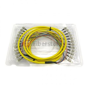
Here are some fiber optic pigtails products in fs.com, as shown in figure:

Multimode LC/SC/ST/FC Pigtail

Multimode LC/SC/ST/FC Pigtail

ingle-mode LC/SC/ST/FC Bunch Pigtail

Our fs.com provide wide degree flexibility on fiber pigtails, including 9/125 single-mode, 62.5/125 multimode 50/125 multimode and 10G 50/125um OM3 types, simplex fiber, 4 fibers, 6 fibers, 8 fibers, 12 fibers, 24 fibers, 48 fibers and so on.These fiber pigtails can be with fan-out kits and full compliant to Telcordia, EIA/TIA and IEC standards. Welcome to our store to know more information.