Category Archives: Single Mode Fiber (SMF)

The Fiber Optic Patch Cord Reliability

Share

Fiber optic patch cords are one of the simplest elements in any optical network, consisting of a piece of fiber optic cable with a connector on each end. Despite its simplicity, the Fiber Optic Patch Cord can have a strong effect on the overall performance of the network. The majority of problems in any network occur at the physical layer and many are related to the patch cord quality, reliability, and performance. Therefore, using patch cords that are more reliable helps reduce the chance of costly network downtime. This article mainy the patch cord reliability.

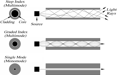
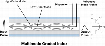
Network designers would prefer components with a history of proven long-term performance. However, since optical networking is a relatively new technology, there is no significant long-term data for many components. Therefore, designers must rely upon testing from the component manufacturer or supplier that can simulate this history and assure the quality and reliability over the life of the network. This paper discusses the importance of quality, reliability, and performance as they relate to industry standards and manufacturing practices. The performance of the patch cord is also studied using a “perfect patch cord” and polishing observations as tools to understand patch cord principles.

Patch cord reliability is guaranteed not only by using quality components and manufacturing processes and equipment, but also by adherence to a successful Quality Assurance program. While patch cords themselves are typically tested 100% for insertion loss and return loss, if applicable, there are many other factors that need to be monitored to insure the quality of the patch cord.

One of the most important factors is the epoxy. Epoxies typically have a limited shelf life and working life, or “pot life.” This information is readily available from the manufacturer. It is absolutely necessary that both of these criteria be verified and maintained during manufacture. Epoxy beyond its expiration date needs to be discarded. Chemical changes affecting the cured properties of the epoxy can occur after this date. This date can also be dependent on storage conditions, which need to be observed.

Most epoxies used in fiber optic terminations are two-part epoxies and, while they cure at elevated temperatures, preliminary cross-linking will begin upon mixing. Once this has started, the viscosity of the epoxy can begin to change, making application more difficult over time. The epoxy can become too thick to fill the ferrule properly and too viscous to enable a fiber to penetrate, causing fiber breakage.

Many of the tooling used in patch cord assembly also has periodic maintenance and a limited tool life. This includes all stripping, cleaving and crimping tools. Most stripping tools, whether they are hand tools or automated machines, can be damaged by the components of the cable, most notably the aramid yarn strength members. Buffer strippers will dull with prolonged usage, increasing the likelihood that they will not cleanly cut the buffer. This can lead to overstressing the fiber when the buffer is pulled off. When a cleaving tool wears out and a clean score is not made, it is almost impossible to detect during manufacturing. However, the result could be non-uniform fiber breakage during the cleave, which can result in either breaking or cracking the fiber below the ferrule endface. In this instance, the connector will have to be scrapped. Even crimp tools require periodic maintenance to insure the proper forces and dimensions are consistent. Crimp dies also have a tendency to accrue epoxy build-up, which can affect the crimping dimensions and potentially damage the connector.

The integrity of the incoming materials and manufacturing processes, once specified, needs to be adhered to all the appropriate guidelines and procedures. The importance of these materials not only has a strong influence on product reliability, but also on product performance.

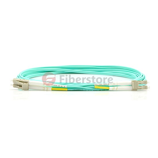
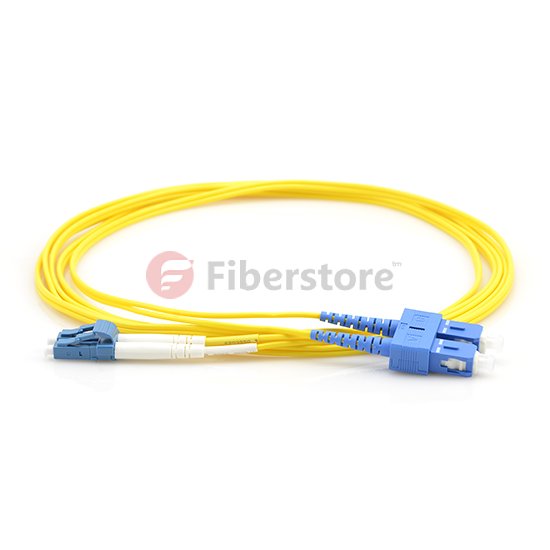
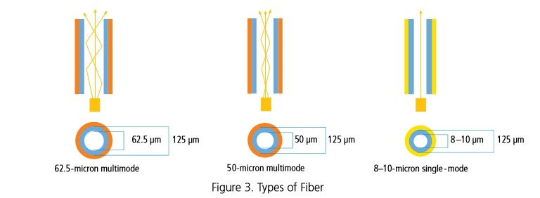
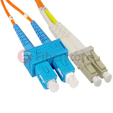
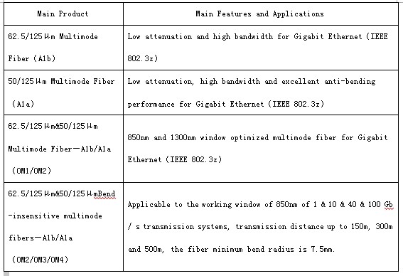
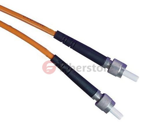
Fiber optic patch cords are fiber optic cables used to attach one device to another for signal routing. It compresses in the entire electric network plank and room that wall plank and the flexibility cabinet needs, causes such the person who passes room merely considerably traditional FC,LC,ST and SC’s connection box in parts.Intelligently the bright and beautiful corporation adopts well-developed technique and installation, and carrying on scale manufacture, the produce performance is good, and the quality is steady dependable. Fiberstore manufactures fiber optic patch cables, fiber optic patch cords, and pigtails. There are LC, SC, ST, FC, E2000, SC/APC, E2000/APC, MU, VF45, MT-RJ, MPO/MTP, FC/APC, ST/APC, LC/APC, E2000, DIN, D4, SMA, Escon, FDDI, RoHS compliant, LSZH, Riser,Plenum, OFNR, OFNP, simplex, duplex, single mode, 9/125, SM, multimode, MM, 50/125, 62.5/125; armored fiber optic patch cords, OM4 patch cord, waterproof fiber optic patch cords, ribbon fiber optic cables and bunched fiber optic cables.

Related Article:  Which Patch Cable Should I Choose for My Optical Transceiver?

Data Center Patch Cords Organized

Share

The benefit of having neat and organized cabling obviously applies to patch cords as much as structured cabling. When you go beyond green considerations, it can be argued that it’s more important to have neat patch cords than structured cabling. Data Center users typically interact with a patching field when installing or servicing hardware rather than structured cabling. Patching fields can be more challenging to maintain in some server environments, however, due to frequent hardware changes and sometimes minimal management of how patches are run.

You can follow several strategies to keep Data Center patch cords organized, thereby improving airflow to equipment, reducing energy consumption of your cooling infrastructure, and easing troubleshooting. (Not to mention maintaining the professional appearance of your Data Center.)

■ Employ a distributed cabling hierarchy: Already mentioned as beneficial for structured cabling, this approach can help with Fiber Optic Patch Cables as well. Having Data Center networking patch fields divided into smaller segments around the Data Center mitigates cabling density and potentially improves airflow to the associated networking equipment.
■ Right-size port counts: Planning the correct number of ports in your Data Center – and reserving space for future expansion of patch fields – helps avoid messy cabling. Installing too many ports can result in unnecessarily large cable bundles; installing too few can trigger picemeal cabling additions in the future that fit awkwardly with the original cabling infrastructure.
■ Use ample wire management: However many connections you install in your network patching fields, be sure to include sufficient vertical and horizontal wire management to handle the maximum quantity of patch cords you plan for. This is of particular importance for some Category 6A patch cords because of their increased outsied cable diameters and soild copper core wire construction. This type of cord promotes a cable memory that can be increasingly difficult to manage as the number of patch cords multiply.
■ Prepatch networking connections: Hardware density in modern Data Centers can involve thousands of cable connections in a single server row. Prepatching networking devices and patch fields all together, before servers are installed, helps ensure that cabling is routed neatly.
■ Provide patch cords in different length – and use them: Stock commonly used types of patch cords in your Data Center in multiple lengths so that whoeer install your hardware can make a neat connection between devices and patching fields. That means correctly routing cabling through the available wire management rather than making a straight-line connection that blocks access to hardware or patch panels. It also means choosing the right length of cable length, so there is no slack to be either coiled up and hidden in the wire management system or left hanging at the end of a connection.

Implementing these cabling practices, first when designing a new Data Center and then when operating, doesn’t just make the facility greener by improving airlow and conserving cabling material, it also makes it easier to use and less prone to accidental down-time.

Fiberstore manufactures and stocks fiber optic patch cables. Our stock cables feature FC/PC, FC/APC, and SMA connectors, and use single mode (SM), polarization-maintaining (PM), or multimode (MM) fiber. Buy LC fiber  optic cable series, same day shipping to your countyre now. We offer ar-coated cables for fiber-to-free space use, lightweight cables for optogenetics, high-power cables, and many other specialty fiber patch cables from stock. We also offer multimode fiber bundles, as well as custom patch cables with 24 hour turnaround on many orders. If you do not see a stock cable that is suitable for your application, please contact us.

Related Article:  Which Patch Cable Should I Choose for My Optical Transceiver?

Brief Introduction to Fiber Optic Patch Cords

Share

Fiber optic patch cord is the simplest fiber optic elements, consisting of a short length of optical fiber with a connector on either end. Since they are used to connect various components and instruments in a fiber optic system, their characteristics in terms of loss and aging determine the overall performance of the system. In principle, when two patch cords are connected, if the fibers are identical, it should result in almost zero loss. In actual practice the loss may not be very small since the fiber may not be completely concentric with the connector center, there could be dust at the tip of the connector, or there could be misalignments when two patch cords are mated. Fiber optic patch cord with different types of fibers and different connector types are available. The typical insertion loss of patch cords is about 0.4 dB, with a return loss of better than 50 dB.

We mustn’t forget the role that optical patch cords play in the practical use of an optical cable system. A patch cord is a short length of a simple optical cable, typically one to five meters, that is used to connect the active or final equipment into the cable plant, usually by way of the patch panel.

The patch cord can be of a single fiber, simplex, or two fibers, duplex. If it is duplex then the convention is to cross the circuit so that A goes to B and B to A, as seen in Figure 1.

Talk about simplex and duplex, we can recommend you some patch cord from our store.

LC-LC Duplex 10G OM4 50/125 Multimode Fiber Optic Patch Cord

lc lc fiber optic patch cord

Cost-effective solution that provides higher bandwidth and transmission rates and supports longer distances with lower loss than 62.5 fiber. Specifically designed for use with today’s narrower aperture components, this LC-LC fiber optic cable is fully compatible with multimode applications. The patented injection molding process provides each connection greater durability in resisting pulls, strains, and impacts from cabling install.

LC-SC Duplex 9/125 Single-mode Fiber Optic Patch Cord

lc sc fiber optic patch cord

● LC-SC Connectors
● Singlemode Duplex fiber optic cable
● Micron: 9/125um
● Complete with Lucent Technologies aqua jacket
● Bandwidth transmitting rates up to 10 gigabits
● All of our fiber optic patch cables feature the high degree connectors
● 100% optically tested to ensure high performance
● Color: Yellow

SC fiber cable is one of the earliest types and one of the most commonly used fiber optic cable, it is convenient to use and cost saving – It is the cheapest type fiber optic cable. SC fiber patch is widely used in fiber optic networks. SC fiber patch cable is with zirconia sleeve and plastic housing.

The patch cord must incorporate exactly the same fiber as is contained within the rest of the cable plant. There is no reason why the connectors on each end need to be the same. What is important is that one end of the patch cord matches that found on the active equipment and the other end matches the patch panel.

Three Common Types Of Fiber Optic Cable

Share

There are three common types of fiber optic cables , as listed below. The suitability of each type for a particular application depends on the fiber optic cable’s characteristics.

The single mode fiber optic cable, sometimes called a single-mode fiber cable, is shown in Figure 1.5(a). The single and multimode step-index fiber cables are the simpplest types of fiber optic cables. Single-mode fiber cables have extremely small core diameters, ranging from 5 to 9.5 um. The core is surrounded by a standard cladding diameter of 125 um. The jacket is applied on the cladding to provide mechanical protection, as shown in Figure 1.3. Jackets are made of one type of polymer in different colours for colour-coding purposes. Single-mode fibers have the potential to carry signals for long distances with low loss, and are mainly used in communication systems. The number of modes that propagate in a single-mode fiber depends on the wavelength of light carried. The number of modes will be given in Equation (1.9). A wavelength of 980nm results in multimode operation. As the wavelength is increased, the fiber carries fewer and fewer modes until only one mode remains. Single-mode operation begins when the wavelength approaches the core diameter. At 1310 nm, for example, the fiber cable permits only one mode. It then operates as a single-mode fiber cable.

singlemode types of fiber optic cables

The multimode types of fiber optic cables, sometimes called a multimode fiber cable. Multimode fiber cables have bigger diameters that their single-mode counerparts, with core diameters ranging from 100 to 970 um. They are available as glass fibers (a glass core and glass cladding), plastic-clas silica (a glass core and plastic cladding), and plastic fibers (a plastic core and cladding). They are also the widest ranging, although not the most efficient in long distances, and they experience higher losses than the single-mode fiber cables. Multimode fiber cables have the potential to carry signals for moderate and long distance with low loss (when optical amplifiers are used to boost the signals to the required power). Plastic fiber optic cable is available in Fiberstore,  it is an optical fiber made out of plastic rather than traditional glass. It offers additional durability for uses in data communications, as well as decoration, illumination and industrial application. FiberStore provides both simplex and duplex plastic optical fibers.

Since light rays bounded through a fiber cable reflect at different angles for different ray pathc, the path lengths of different modes will aslo be different. Thus, different rays take a shorter or longer time to travel the lenth of the fiber cable. The ray that goes straight down the centre of the core without reflecting arrives at the other end faster. Other rays take slightly longer and thus arrive later. Accoringly, light rays entering a fiber at the same time will exit at the other end at different times. In time, the light will spread out because of the different modes. This is called modal dispersion. Dispersion describes the spreading of light rays by various mechanisms. Modal dispersion is that type of dispersion that results from the varying modal patch lengths in the fiber cable.

Multimode graded-index fiber are sometimes called graded-index fiber cables (GRIN). Graded-index and multimode fiber cables have similar diameters. Common graded-index fibers have core diameters of 50,62.5, or 85 um, with a cladding diameter of 125 um. The core consist of numerous concentric layers of glass, somewhat like the annular rings of a tree or a piece of onion. Each successive layer expanding outward from the central axis of the core until the inner diameter of the cladding has a lower index of refrection. Light travels faster in an optical material that has a lower index of refraction. Thus, the further the light is from the centre axis, the greater its speed. These types of fiber optic cable are popular in applications that require a wide range of wavelenths, in particular telecommunication, scanning, imaging, and data processing stystems. In particular telecommunication,  Multimode OM4 fiber optic cable is used in any data center looking for high speeds of 10G or even 40G or 100G. OM4 multimode fiber are ideal for using in many applications such as Local Area Networks (LAN) backbones, Storage Area Networks (SAN), Data Centers and Central Offices.

multimode fiber

You may have got some basics of types of fiber optic cables. Fiberstore provides a wide range of types of fiber optic cable with detailed specifications displayed for your convenient selecting. Per foot price of each fiber cable is flexible depending on the quantities of your order, making your cost of large order unexpected lower. Customers can also have the flexibility to custom the cable plant to best fit their needs.

Related Article: The Advantages and Disadvantages of Optical Fiber

Related Article: What Kind of Fiber Patch Cord Should I Choose?

The types of Fiber Optic Cable

Share

Fiber optic cables are the medium of choice in tele communications infrastructure, enabling the transmission of high-speed voice, video, and data traffic in enterprise and service provider networks. Depending on the type of application and the reach to be achieved, various types of fiber may be considered and deployed.

Multimode vs. Single-Mode Cable

Multimode cable has a large-diameter core and multiple pathways of light. The two most commnon are 50 micron and 62.5 micron.

Multimode fiber optic cable can be used for most general data and voice fiber applications, such as bringing fiber to the desktop, adding segments to an existing network, and in smaller applications such as alarm systems. Both 50- and 62.5-micron cable feature the same cladding diameter of 125 microns, but 50-micron fiber cable features a smaller core (the light-carrying portion of the fiber). Also, both also use either LED or laser light sources.

Although both can be used in the same way, 50-micron cable is recommended for premise applications (backbone, horizontal,and intrabuilding connections) and should be considered for any new construction and installations. The big difference between the two is that 50-micron cable provides longer link lengths and/or higher speeds, particularly in the 850-nm wavelength. 50 micron OM4 fiber optic cable now save up to 30% off sale in our store, if have interest, search Fiberstore on google.

Single-mode cable has a small 8–10-micron glass core and only one pathway of light. With only a single wavelength of light passing through its core, single-mode cable realigns the light toward the center of the core instead of simply bouncing it off the edge of the core as multimode does.

Single-mode cable provides 50 times more distance than multimode cable does. Consequently, single-mode cable is typically used in high-bandwidth applications and in long-haul network connections spread out over extended areas, including cable television and campus backbone applications. Telcos use it for connections between switching offices. Single-mode cable also provides higher bandwidth, so you can use a pair of single-mode fiber strands full-duplex for up to twice the throughput of multimode fiber.

Fiber Optic Cable

Simplex vs. duplex Patch cables

Multimode and single-mode patch cables can be simplex or duplex.

Simplex has one fiber, while duplex zipcord has two fibers joined with a thin web. Simplex (also known as single strand) and duplex zipcord cables are tight-buffered and jacketed, with Kevlar strength members. Because simplex fiber optic cable consists of only one fiber link, you should use it for applications that only require one-way data transfer. For instance, an interstate trucking scale that sends the wieght of the truck to a monitoring station or an oil line monitor that sends data about oil flow to a central location.

Use duplex multimode or single-mode fiber optic cable for applications that require simultaneous, bidirectional data transfer. Workstations, fiber switches and servers, Ethernet switches, backbone ports, and similar hardware require duplex cable.

Indoor/Outdoor Cable

Indoor/outdoor cable uses dry-block technology to seal ruptures against moisture seepage and gel-filled buffer tubes to halt moisture migration. Comprised of a ripcord, core binder, a flame-retardant layer, overcoat, aramid yarn, and an outer jacket, it is designed for aerial, duct, tray, and riser applications.

PVC (Riser) vs. Plenum-Rated

PVC cable (also called riser-rated cable even though not all PVC cable is riser-rated) features an outer polyvinyl chloride jacket that gives off toxic fumes when it burns. It can be used for horizontal and vertical runs, but only if the building features a contained ventilation system. Plenum can replace riser, but riser cannot be used in plenum spaces.

“Riser-rated” means that the jacket contains PVC. The cable carries a CMR (communications riser) rating and is not for use in plenums.

Distribution-Style vs. Breakout-Style

Distribution-style cables have several tight-buffered fibers bundled under the same jacket with Kevlar or fiberglass rod reinforcement.These cables are small in size and are used for short, dry conduit runs, in either riser or plenum applications. The fibers can be directly terminated, but because the fibers are not individually reinforced, these cables need to be broken out with a “breakout box” or terminated inside a patch panel or junction box.

Breakout-style cables are made of several simplex cables bundled together, making a strong design that is larger than distribution cables. Breakout cables are suitable for conduit runs and riser and plenum applications.  Fiberstore supply high quality Multi-purpose Breakout Cables which facilitates easy installation of fiber-optic connectors. Buy Bulk Fiber Optic Cable on our worldwide online store with your confidence.

Loose-Tube vs. Tight-Buffered Fiber Optic Cable

There are two styles of fiber optic cable construction: loose tube and tight buffered. Both contain some type of strengthening member, such as aramid yarn, stainless steel wire strands, or even gel-filled sleeves. But each is designed for very different environments.

Loose-tube cable is specifically designed for harsh outdoor environments. It protects the fiber core, cladding, and coating by enclosing everything within semi-rigid protective sleeves or tubes. Many loose-tube cables also have a water-resistant gel that surrounds the fibers. This gel helps protect them from moisture, which makes loose-tube cable great for harsh, high-humidity environments where water or condensation can be a problem. The gel-filled tubes can also expand and contract with temperature changes. There are many fiber cable types of loose tube, for example, ADSS Cable is used by electrical utility companies as a communications medium.

But gel-filled loose-tube cable is not the best choice when cable needs to be routed around multiple bends, which is often true in indoor applications. Excess cable strain can force fibers to emerge from the gel.

Tight-buffered cable, in contrast, is optimized for indoor applications. Because it’s sturdier than loose-tube cable, it’s best suited for moderate-length LAN/WAN connections or long indoor runs. It’s easier to install, as well, because there’s no messy gel to clean up and it doesn’t require a fan-out kit for splicing or termination. You can install connectors directly to each fiber.

Low-loss Connectivity For Multimode Fiber Applications

Share

Optical insertion loss budgets are now one of the top concerns among data center managers, especially in today’s large virtualized server environments with longer-distance 40 and 100 gigabit Ethernet (GbE) backbone switch-to-switch deployments for networking and storage area networks (SANs). In fact, loss budgets need to be carefully considered during the early design stages of any data center—staying within the loss budget is essential for ensuring that optical data signals can properly transmit from one switch to another without high bit error rates and performance degradation.

low-loss-multifiber-connectivity

With the length and type of the fiber optic cable and number of connectors and splices all contributing to the link loss, data center managers are faced with the challenge of calculating each connection point and segment within their fiber channels. Multi-fiber push on (MPO) or mechanical transfer push on (MTP) connectors are rapidly becoming the norm for switch-to-switch connections due to their preterminated plug and play benefits and ease of scalability from 10 to 40 and 100 gigabit speeds. Unfortunately, typical MPO MTP module insertion loss may not allow for having more than two mated connections in a fiber channel, which significantly limits design flexibility and data center management. Low loss, rather than standard loss, MPO/MTP connectors better support multiple mated connections for flexibility over a wide range of distances and configurations while remaining within the loss budget.

MTP LC

Typical MPO/MTP connectors, which are required for 40 and 100 GbE eployments have insertion loss values that range from 0.3 dB to 0.5 dB. Typical LC multimode fiber connectors have loss values that range from 0.3 dB to 0.5 dB. While better than the allowed 0.75 dB TIA value, typical connector loss still limits how many connections can be deployed in 10, 40 and 100 GbE channels. For example, with an LC connector loss of 0.5 dB, a 300-meter 10 GbE channel over OM3 fiber can include only three connectors with no headroom. Having just two or three connections prevents the use of cross connects at both interconnection (MDA) and access switches (HDA).

Due to improvements in connector technology and manufacturing techniques, Fiberstore has succeeded in lowering the loss to 0.20 dB for MTP connectors and to 0.15 dB (0.1 dB typical) for LC and SC connectors, well below the industry standard of 0.75 dB and loss values offered by other manufacturers.

For 10 GbE, Fiberstore low loss LC fiber jumpers offer a loss of 0.15 dB (typical 0.1 dB) and Fiberstore low loss plug and play MTP to LC or SC modules offer a loss of 0.35 dB (typical 0.25 dB). For 40 and 100 GbE, MTP to MTP pass-through adapter plates and MTP fiber jumpers offer a loss of 0.2 dB. These lower loss values allow data center managers to deploy more connection points in fiber channels, enabling the use of distribution points or cross connects that significantly increase flexible configuration options.

Table 2 below provides an example of how many connections can be deployed in 10, 40 and 100 GbE channels over OM3 and OM4 multimode fiber using low loss MTP to LC modules for 10 GbE and low loss MTP to MTP pass-through adapters for 40 and 100 GbE versus standard loss solutions.

As indicated in Table 2, the use of low loss connectivity allows for four connections in a 10 GbE OM3 or OM4 channel compared to just two when using standard loss connectivity. Low loss connectivity allows for eight connections in a 100- meter 40/100 GbE channel over OM3 versus just four connections using standard loss, and five connections in a 150-meter 40/100 GbE channel over OM4 fiber compared to just two connections using standard loss. Deploying cross connects between interconnection and access switches requires a minimum of four connections, depending on the configuration. Therefore, cross connects in a full-distance optical channel are simply not feasible without low loss connectivity.

Figures 6, 7 and 8 shows some example scenarios for deploying cross connects in 10 GbE and 40/100 GbE channels over OM3 and OM4 fiber using Fiberstore low loss fiber connectivity. In Figure 6, all changes are made at the cross connect with LC fiber jumpers. The switches remain separate and the permanent MTP trunk fiber cables need only be installed once. The cross connect can be placed anywhere within the channel to maximize ease of deployment and manageability.

MTP Trunk Cable

Figure 7. shows an OM3 40/100 GbE channel with six Fiberstore low loss MTP-MTP pass-through adapter plates and low loss trunks. This scenario offers 0.4 dB of headroom and provides even better manageability and security. All changes are made at the cross connects via MTP fiber jumpers, switches remain separate, and the MTP trunk cables need only be installed once.Once again, the cross connects can be located anywhere in the data center for maximum flexibility. This allows for one-time deployment of high fiber-count cabling from the cross connect at the interconnection switch to the cross connect at the access switch. Adding additional access switches can be accomplished with short fiber runs from the cross connect.

Figure 7: For maximum flexibility, manageability and security, up to eight low loss MTP-MTP pass-through adapters can be deployed using low loss trunks in a 100-meter 40/100 GbE switch-to-switch backbone channel over OM3 fiber.

If the loss budget does not permit deploying six MTP to MTP adapters, one option is to deploy MTP to LC or MTP to MTP jumpers from the cross connect to the equipment, depending on the equipment interface. For example, if using OM4 fiber to extend the channel distance to 150 meters, up to five Low Loss MTP-MTP pass through adapters can be deployed as shown in Figure 8.

The Specific Instructions of Optical Fiber Patch Cord

Share

Optical fiber communication refers to modulate voice, video and data signals to the fiber patch cord as a communication transmission medium. The optical fiber can be divided into multimode fiber and single mode fiber.

Single Mode Fiber Patch Cord

The central glass core of single mode fiber is fine (core diameter is usually 9 or 10μm), it only can transfer one mode light. The mode dispersion is small, and it is for remote communication, but it plays a major role in the chromatic dispersion so that the spectral width of the single mode fiber has a higher light stability and the requirement that the spectral width is narrower and better stability. 1000 Mb/s fiber optic transmission distance is 550m-100km. As we all know, we commonly see 9/125μm single mode optical fiber in the market. And single mode 9/125um fiber optic patch cables are recommended for Fast, Gigabit, 10G Ethernet or SONET OC3-OC192 rate optical connections. Low prices make the 9/125um fiber attractive for in-building projects too, because of the reliability and choice of using a single-strand of fiber for same communications (simplex cords are used on Bi-Directional data links).

Multimode Fiber Patch Cord

The central glass core of Multimode fiber is coarse (50 or 62.5μm), multiple modes of light can pass. However, its mode dispersion is among large, which limits the frequency of the transmitted digital signal, and with the increase in distance will be more severe. Multi-mode fiber transmission distance is relatively recent, generally only a few kilometers. 1000 Mb/s fiber optic transmission distance is 220m-550m. In general, we can find 62.5/125um Multi-mode fiber optic cable in the market. 62.5/125um multimode fiber cables are recommended for Fast Ethernet and up to OC3/STM1 rate optical connections. They can also be used for Gigabit Ethernet multi-mode connections on distances less than 275 meters. 62.5/125um fiber is most used inside buildings.

Types of Fiber Patch Cord

In the network wiring, the more applications optic fiber has three types, there are 62.5μm/125μm multimode fiber, 50μm/125μm multimode fiber, and 9μm/125μm single mode fiber. According to the rate and transmission distance, we can distinguish and choose single/multimode optic fiber. Tied the fiber bundle, outside has the protective housing, which is called fiber cable. According to different application environments, the cable can be divided into indoor and outdoor fiber optic cable.

Fiber refers that the fiber jumper with a desktop computer or device connected directly to facilitate the connection and manage the device. Fiber jumpers are also divided into two multimode and single-mode, which are connected with single mode and multimode fiber. Jumper for an active connection cable between the two devices without connectors (as distinguished: patch (patch cord) is one or both ends with connectors; jumper is at both ends of the cable has a fiber optic connectors, the device can be directly connected, but only one end of the fiber pigtail connector and the other end to the fiber splicing).

Fiber Patch Cord Connector Types

Fiber patch cord connector shape can be divided into FC, SC, ST, LC, etc. According TO ferrule grinding mode, it can be divided into PC (plane), UPC (spherical surface), APC (8 degrees inclined plane ) and other (cable optical transceiver general requirements FC / APC connector). According to the type of optical fiber, it can be divided into the single mode optical fiber, 50/125 multimode, 62.5/125 multimode and Gigabit, etc. According to the optical fiber connetor, we commonly see LC, SC fiber patch cord in the market,  the following products are LC-SC fiber in our online store, if you have interest, you can go to our store to have a see.

LC SC Fiber patch cord

Fiber patch cord products are widely applied, it applies in the communications room, fiber to the home, local area networks, fiber optic sensors, fiber optic communication systems, fiber optic transmission equipment connected, defense readiness and so on. Apply to cable television, telecommunications networks, computer networks and optical fiber test equipment. Broken down mainly used in several ways.

The Characteristics Of Single mode Fiber and Multimode Fiber

Share

Fiber optic cable is the most common and important transmission medium in optical communication system. It consists of a single glass core, the cladding layer close to the core, a primary coating layer and a protective layer composed of plastic cap.(Cylindrical fiber, the core, cladding and coating layers composed of three parts.) Core and the cladding layer consists of two different optical properties of the medium constituting the medium refractive index of light than the interior of a surrounding medium high refractive index. In the periphery of the package as the cover layer of opaque material, as the light is prevented from escaping from the surface during interspersed. Fiber optic cable has two types: single mode fiber and multimode fiber.

Multimode Fiber

When the geometry of the fiber is much larger than the wavelength of light (about lμm), optical transmission process will be a significant presence of dozens or even hundreds of transport modes, such as the fiber is called multimode fiber.

Due to different propagation modes having different phase propagation velocity, thus, long-distance transmission is generated through mode dispersion (after long-distance transmission delay difference is generated, resulting in the optical pulse broadening). Side mode dispersion will narrow the bandwidth of multimode fiber, the transmission capacity is reduced, and therefore, multi-mode fiber is only suitable for low speed, short-distance optical fiber communication, data communication is currently a large number of multi-mode fiber local area network.

Main products and application performance of multimode fiber in the following table:

Multimode Fiber
The related products about 62.5/125mm multimode fiber from fs.com, it is below:

Duplex OM1 62.5 125 Fiber Patch Cable

The product about  50/125mm OM2 multimode fiber

Duplex OM2 50 125 Fiber Patch Cable

Single Mode Fiber 

When the geometry of the fiber is small, and the wavelength of the same order as the core diameter in the range of 4-10μm, the optical fiber allows only one mode (basic mode) in which the transmission, the remaining high-order mode are all turned off, so that said single mode fiber. Avoid the mode dispersion single mode fiber, suitable for large-capacity long-distance transmission.

IEC 60793-2 and IEC 60793-2-50 single mode fiber will be divided into B1.1, B1.2, B1.3, B2, B4, B5, B6 and other categories, ITU-T also G.652, G .653, G.654, G.655, G.656, G.657 and other recommendations were standardized definition and characteristics of various single mode fiber, and each part of the GB / T 9771 with reference to IEC 60793-2-50 ITU-T G.65x series formulation.

A given type of single mode fiber, the mode field diameter by (also called effective area), the dispersion coefficient, dispersion slope, wavelength cutoff adapted to optimize the parameters, and access ways for different applications.

Related Article: What’s the Difference: Single Mode vs Multimode Fiber

The Knowledge Of Fiber Optic Cables

Share

The Basics Knowledge Of Fiber Optic Cables

1.1 What is Fiber Optic Calbe?

The fiber optic cable mainly consist of a protective plastic sleeve and plastic sheath structure, no internal cable gold, silver, copper and aluminum and other metals, usually no recycling value. Fiber Patch Cables is a certain amount of the composition according to a certain way of cable core, outsourcing has a jacket, and some also cover the outer sheath to achieve a communication line optical signal transmission. It is the optical fiber cable (optical transmission medium) after the formation of a certain process.

1.2 The factors that affect fiber performance and lifetime

A) Stress: Causes fiber breaks or attenuation increases
B) Water and moisture: the fiber is easy to break (brittle), the impact of life
C) Hydrogen (pressure): the role of a fiber having a hydrogen pressure of mutated fiber attenuation curve of the absorption peak at 1240nm, 1310nm, and the attenuation significantly increased at a wavelength of 1550nm.

1.3 Classification of fiber optic cable

A) By fiber optic cable in the state in points: tight structure, loose structure, semi-loose semi-tight structure
B) By the cable core structure: central tube, Stranded, skeleton, Mode Conditioning Patch Cable, MPO Fiber cable.
C) By the conditions of the cable laying: aerial, pipeline, buried and underwater fiber optic cable
D) By the condition of the use of fiber optic cable with the different types: Single Mode Fiber Patch Cable, Multimode Fiber Cable.
E) By the Environment occasion of using fiber cable: outdoor cables, indoor cables.

1.4 The basic properties of fiber optic cable

Transmission characteristics of the cable depends on the coated fiber. Mechanical properties of the fiber optic cable requirements and environmental characteristics determined by the conditions of use. After the cable production out of the main items of these features, such as tension, pressure, torsion, bending, shock, vibration and temperature, to do routine testing in accordance with national standards. Finished cable is generally required to give the following characteristics, parameters of these characteristics can be analyzed to calculate the empirical formula, here we only briefly qualitative description.

1) The characteristics of Tensile properties

Maximum tension cable can withstand depends reinforcement material and cross-sectional area, generally require more than 1km cable weight, most cable at 100 ~ 400kg range.

2) The characteristics of Pressure

Side cable can withstand the maximum pressure depends on the material and structure of the sheath, most of the cable can withstand the maximum pressure side 100 ~ 400kg/10cm.

3) Bending properties

The main characteristics of bending depends on the material and structure of the core, the cladding and the relative refractive index difference cable. Practical minimum bend radius optical fiber is generally 20 ~ 50mm, the minimum cable bend radius is generally 200 ~ 500mm, equal to or greater than the minimum bend radius of the fiber. Under the above conditions, the fiber of optical radiation caused by the additional loss can be ignored, if less than the minimum bending radius, the additional loss increased dramatically.

4) Temperature properties

Fiber itself has good temperature characteristics. Cable temperature characteristics of design choice and depends on the configuration of the cable material, the temperature characteristics optical fiber which use of secondary coated loose tube cable is better. When the temperature changes, the optical fiber loss increases, primarily due to the cable material (plastic) than the coefficient of thermal expansion of the fiber material (quartz) 2 ~ 3 orders of magnitude, in the thermal expansion or shrinkage process, the fiber produced by the stress. In China, the use of temperature requirements for fiber optic cable, usually in the low-temperature region of -40 ℃ ~ +40 ℃, high temperature region is -5 ℃ ~ +60 ℃.

1.5 Cable moisture measures

A) Radial waterproof – fiber cream and jelly filled cables, metal belt longitudinally, PE jacket

B) Axial waterproof – fiber cables cream and cream filling, water blocking ring, waterproof tape, water blocking yarn, single core strengthening

Know more knowledge of fiber optic cables, you can go to fs.com. fs.com is leading manufacturer and supplier of fiber optic cable products such as fiber optic patch cables, MPO Fiber cable, fiber optic pigtails, fiber optic attenuators, fiber optic connectors, fiber optic adapters, fiber optic transceivers and much more. Every product manufactured by us, is put through stringent quality control standards and procedures to provide only premium quality product to the client. As such our fiber optic patch cords are guaranteed to meet and also go beyond the expectations of the customers.

FAQ In Fiber Optic Cabling

Share

Firstly, do choose multimode or single mode fiber? What is the difference between them?

In general, the user requests the fiber transmission distance is relatively short, such as a few hundred meters, can be Multimode Fiber Optic Cable. However, if the transmission distance has several kilometers, even further, without the use of signal repeaters must be single-mode fiber.

Secondly,  Do choose 4 core, 6 core, 8 core or more core Fiber Optic Patch Cables?

Fiber complete the transfer task, it must receive at least one first serve two core. In fact, there are 4,6,8 or more optical fiber core, the core can be used as extra backup, you can do more transmission channels.

Thirdly,  Does use wall or rack-mounted fiber optic patch panel cable box?

Wall fiber boxes are generally used in small fiber-optic network, for example, a 4-core optical fiber, but if there is more number of fiber optic, it shows the advantages of rack patch panel. It can be placed inside the routers and switches with a cabinet for easy centralized management and more secure.

And then, What is the connector type of FC,SC,ST,LC,MTRJ, and Which one can be choose?

These different interfaces have used in different environments, they differ mainly in the method and shape connection, is it the same as the screws tighten or direct card? Is square or round? Large or small mouth opening (mouth relatively large place occupied by a small mouth can have greater port density)? Two heads separately or synthetic one? Users need not be too concerned about the specific interface, to note that if the extension already exists in the case of older fiber optic systems, you have to match each job.

Finally, Is the choice of the center beam tube or Stranded cable?

Central tube Fiber Optic Cable placed in the center portion of the cable core, many of the core tube synthesis bunch shape, and the outer cable surrounding two wires placed in parallel to ensure tensile strength.

The central part of Stranded cable strengthen stereotypes core fiber. Fiber core surrounded by a peripheral that strengthen the core, many cores together to form the shape layer by layer.

How to identify fiber optic, is single mode or multimode fiber?

The first is a relatively simple method for indoor fiber, it can be identified by single-mode fiber and multimode fiber external color, Single Mode Fiber Cable is yellow, Multimode Fiber Optic Cable is red. Including Fiber optic patch cords and Fiber pigtails are the same recognition.

For MPO Fiber, generally can be identified by model code, there are a bunch of characters on the cable sheath, such GYXTW-4-A1a, the last paragraph begins with A on behalf of the multi-mode fiber, beginning with B represents a multi-mode fiber, a little more detail, A1a representing 50/125 multimode fiber specifications, A1b representatives 62.5/125 multimode fiber specifications, B1.1 representatives of non-dispersion shifted single-mode fiber and so on.

If this way can not be identified single mode fiber or multimode fiber, it is only through a special device to identify, as fiber splicing machine, it will automatically recognize the single mode or multimode fiber, single mode will show SM, multi-mode will show MM.