

Optical insertion loss budgets are now one of the top concerns among data center managers, especially in today’s large virtualized server environments with longer-distance 40 and 100 gigabit Ethernet (GbE) backbone switch-to-switch deployments for networking and storage area networks (SANs). In fact, loss budgets need to be carefully considered during the early design stages of any data center—staying within the loss budget is essential for ensuring that optical data signals can properly transmit from one switch to another without high bit error rates and performance degradation.

With the length and type of the fiber optic cable and number of connectors and splices all contributing to the link loss, data center managers are faced with the challenge of calculating each connection point and segment within their fiber channels. Multi-fiber push on (MPO) or mechanical transfer push on (MTP) connectors are rapidly becoming the norm for switch-to-switch connections due to their preterminated plug and play benefits and ease of scalability from 10 to 40 and 100 gigabit speeds. Unfortunately, typical MPO MTP module insertion loss may not allow for having more than two mated connections in a fiber channel, which significantly limits design flexibility and data center management. Low loss, rather than standard loss, MPO/MTP connectors better support multiple mated connections for flexibility over a wide range of distances and configurations while remaining within the loss budget.
Typical MPO/MTP connectors, which are required for 40 and 100 GbE eployments have insertion loss values that range from 0.3 dB to 0.5 dB. Typical LC multimode fiber connectors have loss values that range from 0.3 dB to 0.5 dB. While better than the allowed 0.75 dB TIA value, typical connector loss still limits how many connections can be deployed in 10, 40 and 100 GbE channels. For example, with an LC connector loss of 0.5 dB, a 300-meter 10 GbE channel over OM3 fiber can include only three connectors with no headroom. Having just two or three connections prevents the use of cross connects at both interconnection (MDA) and access switches (HDA).
Due to improvements in connector technology and manufacturing techniques, Fiberstore has succeeded in lowering the loss to 0.20 dB for MTP connectors and to 0.15 dB (0.1 dB typical) for LC and SC connectors, well below the industry standard of 0.75 dB and loss values offered by other manufacturers.
For 10 GbE, Fiberstore low loss LC fiber jumpers offer a loss of 0.15 dB (typical 0.1 dB) and Fiberstore low loss plug and play MTP to LC or SC modules offer a loss of 0.35 dB (typical 0.25 dB). For 40 and 100 GbE, MTP to MTP pass-through adapter plates and MTP fiber jumpers offer a loss of 0.2 dB. These lower loss values allow data center managers to deploy more connection points in fiber channels, enabling the use of distribution points or cross connects that significantly increase flexible configuration options.
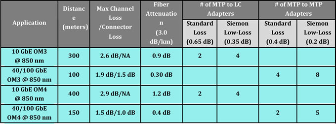
Table 2 below provides an example of how many connections can be deployed in 10, 40 and 100 GbE channels over OM3 and OM4 multimode fiber using low loss MTP to LC modules for 10 GbE and low loss MTP to MTP pass-through adapters for 40 and 100 GbE versus standard loss solutions.
As indicated in Table 2, the use of low loss connectivity allows for four connections in a 10 GbE OM3 or OM4 channel compared to just two when using standard loss connectivity. Low loss connectivity allows for eight connections in a 100- meter 40/100 GbE channel over OM3 versus just four connections using standard loss, and five connections in a 150-meter 40/100 GbE channel over OM4 fiber compared to just two connections using standard loss. Deploying cross connects between interconnection and access switches requires a minimum of four connections, depending on the configuration. Therefore, cross connects in a full-distance optical channel are simply not feasible without low loss connectivity.
Figures 6, 7 and 8 shows some example scenarios for deploying cross connects in 10 GbE and 40/100 GbE channels over OM3 and OM4 fiber using Fiberstore low loss fiber connectivity. In Figure 6, all changes are made at the cross connect with LC fiber jumpers. The switches remain separate and the permanent MTP trunk fiber cables need only be installed once. The cross connect can be placed anywhere within the channel to maximize ease of deployment and manageability.
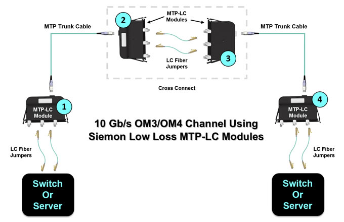
Figure 7. shows an OM3 40/100 GbE channel with six Fiberstore low loss MTP-MTP pass-through adapter plates and low loss trunks. This scenario offers 0.4 dB of headroom and provides even better manageability and security. All changes are made at the cross connects via MTP fiber jumpers, switches remain separate, and the MTP trunk cables need only be installed once.Once again, the cross connects can be located anywhere in the data center for maximum flexibility. This allows for one-time deployment of high fiber-count cabling from the cross connect at the interconnection switch to the cross connect at the access switch. Adding additional access switches can be accomplished with short fiber runs from the cross connect.
Figure 7: For maximum flexibility, manageability and security, up to eight low loss MTP-MTP pass-through adapters can be deployed using low loss trunks in a 100-meter 40/100 GbE switch-to-switch backbone channel over OM3 fiber.
If the loss budget does not permit deploying six MTP to MTP adapters, one option is to deploy MTP to LC or MTP to MTP jumpers from the cross connect to the equipment, depending on the equipment interface. For example, if using OM4 fiber to extend the channel distance to 150 meters, up to five Low Loss MTP-MTP pass through adapters can be deployed as shown in Figure 8.