Category Archives: MPO/MTP solutions

40GBASE-SR4/CSR4 QSFP+ Transceiver Direct Connection Cabling

Share

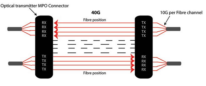
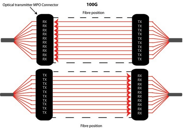
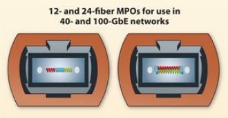
As we all know, the standard specifies MPO as a connector to the 40GBASE-SR4/CSR4 QSFP+ transceiver. To connect a QSFP+ to QSFP+, we usually use a MTP 12-fiber trunk cable. In the 40GBASE-SR transmission, there are eight fibers associated with the channel—four fibers for the TX signal and four fibers for the RX signal. Therefore only 8 of the 12 fibers are used, where the remaining four are not used, and can optionally be not present in the cable. So we can also choose a MTP 8-fiber trunk cable for connectivity. This article explains 40G QSFP+ SR4/CSR4 transceiver to 40G QSFP+ SR4/CSR4 transceiver cabling selections.

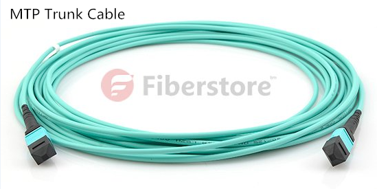
How to Choose Right  MTP Trunk Cables? 
In addition to using a MTP 8-fiber trunk cable or MTP 12-fiber trunk cable, there are a number of other factors also needed to be considered when to choose a right MTP trunk cable for 40G QSFP+ SR4/CSR4 transceiver connectivity.

  • Use single-mode or multimode MTP trunk cable?

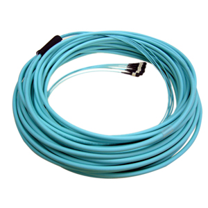
In the market, both single-mode and multiode MTP trunk cable are available. Which one should I use? According to 40GBASE-SR4 standards, 40G QSFP+ SR4 transceiver supports link lengths of 100 meters and 150 meters, respectively, on laser-optimized OM3 and OM4 multimode fibers. Therefore, to connect a 40G QSFP+ SR4  to 40G QSFP+ SR4, we should choose OM3 or OM4 multimode MTP trunk cables.

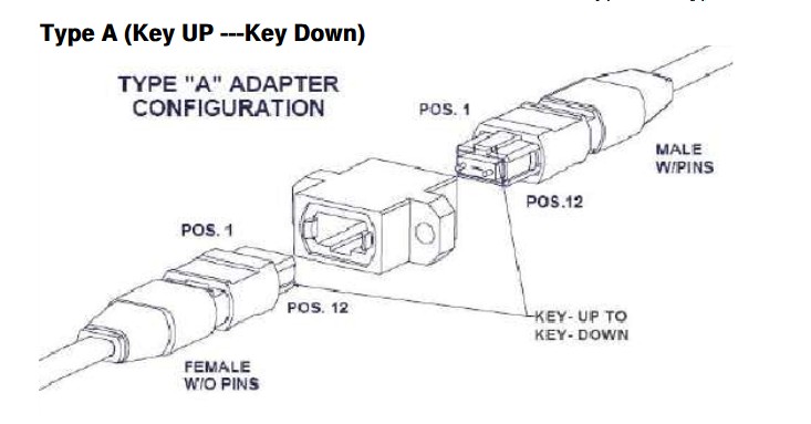
  • MTP trunk cable polarity selection: A, B or C?

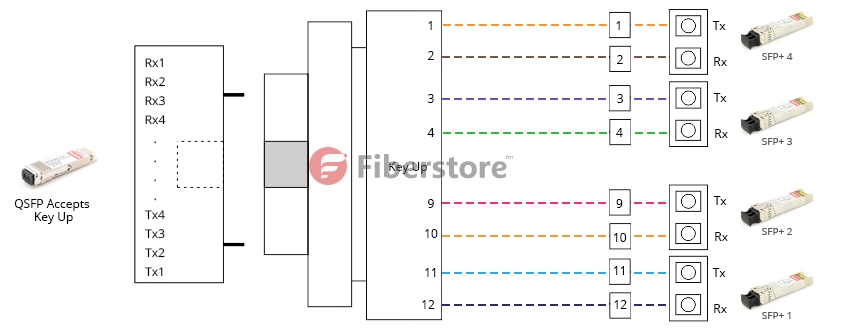
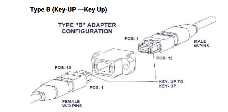
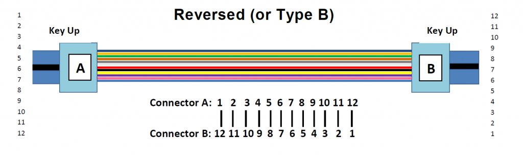
In terms of MTP trunk cable, there are three kinds of polarity options (A, B and C). Which one to choose? In fact, according to the IEEE 40GBASE-SR4 specifications, we must select a type B MTP 8-fiber or MTP 12-fiber trunk cable. The type B trunk cable has opposing connectors with both keys oriented facing up, however the fiber positions are reversed at each end i.e. the fiber at position 1 at one end is connected to position 12 in the connector at the opposing end.

Type-B-MTP-trunk-cable

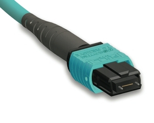
  • Choose male or female MTP trunk cable?

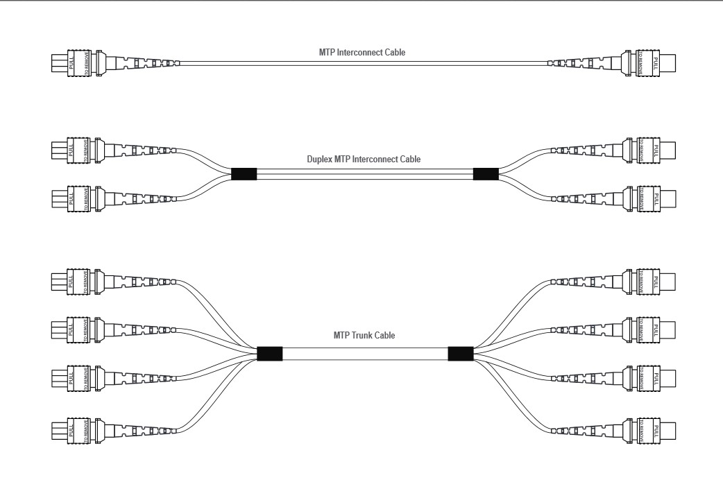
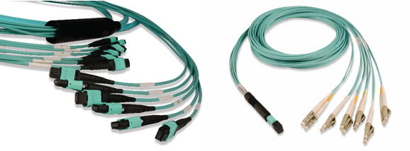
In terms of a MPO connector, it is divided into male and female types. They ensure that the adapter holds the connector with the correct ends aligned with each other. A MPO trunk cable usually has two MPO connector on each side. Therefore, MTP trunk cables are available in male–male and female–female two versions. According to IEEE standards, MPO optics in a 40G QSFP+ SR4 transceiver are always male connectors, and therefore will always accept female MPO connectors. So if we want to connect a 40G QSFP+ SR4 transceiver  to a 40G QSFP+ SR4 transceiver successfully, we must choose a female–female MTP trunk cable.

40G QSFP+ SR4/CSR4 to 40G QSFP+ SR4/CSR4 Cabling Selections
In order to satisfy different cabling requirement, we may choose different cabling methods. And different cabling methods call for many different cabling infrastructure. Following are four type common cabling methods to connect a 40GBASE-SR4/CSR4 QSFP+ to 40GBASE-SR4/CSR4 QSFP+.

  • Direct connection for 40 Gigabit Ethernet parallel optic transceiver

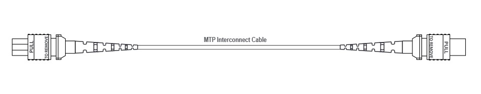
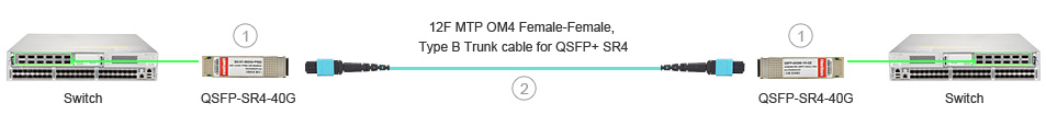
When directly connecting one QSFP+ MPO/MTP interface transceiver to another, a Type-B female MPO/MTP to female MPO/MTP cable is required. This type of direct connectivity is only suggested for short distances within a given row of racks/cabinets. Following picture shows two QSFP+ transceivers being connected with a MTP female cable.

solutions_40G_pic01

Item Number FS Correlative Product Description FS Part Number
1 40GBASE-SR4 QSFP+, 850nm, 150m, MMF, MPO interface QSFP-SR4-40G
2 12 Fibers OM4, 12 Strands MTP Trunk Cable, Female to Female, Type B Polarity ( MTP/ MPO, OM4/ OM3 optional. Various lengths available) FS12OM4-2MTP-FF-B
  • 40GbE direct interconnect with MTP trunk cable and patch panel

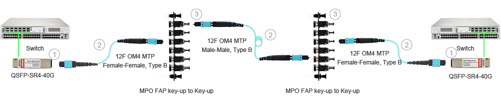
For distances less than 400 meters, the use of FS MPO/MTP multi-mode fiber cabling is generally the preferred cabling method. The next solution is similar to the previous, but instead of using a 12-fiber jumper directly, the MPO/MTP adapter panel is interconnected. Following picture shows the distribution switch and FS optics and cabling options with corresponding item details for a QSFP+ to QSFP+ multi-mode interconnection.

solutions_40G_pic02

Item Number FS Correlative Product Description FS Part Number
1 40GBASE-SR4 QSFP+, 850nm, 150m, MMF, MPO interface QSFP-SR4-40G
2 12 Fibers OM4, 12 Strands MTP Trunk Cable, Female to Female, Type B Polarity ( MTP/ MPO, OM4/ OM3 optional. Various lengths available) FS12OM4-2MTP-FF-B
3 12 Ports MTP/MPO Fiber Adapter Panel, key-up to key-up FAP-HV-12MTPUUD
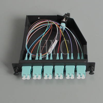
  • 10Gig migrate to 40GbE by interconnecting MTP LGX cassette and MTP trunk cable

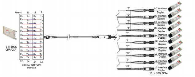
Following picture shows one link with a breakout of the QSFP+ with the use of an MPO/MTP LGX cassette to four 10G SFP+ links. A Type-B female MPO/MTP to Female MPO/MTP assembly is used between the MPO/MTP LGX cassette and 40GbE transceiver. The connections to the SFP+ transceivers is accomplished with OM3/OM4 Uniboot LC duplex fiber patch cables.
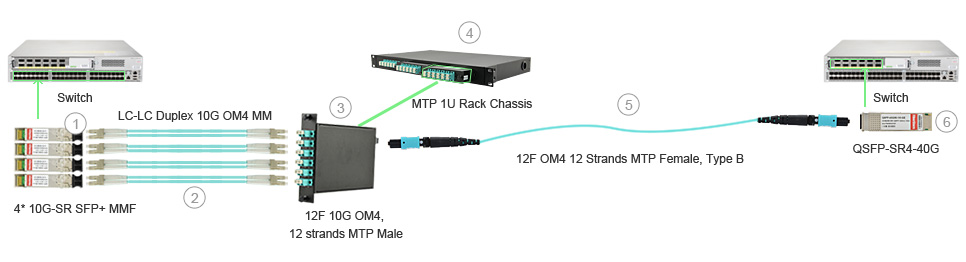
solutions_40G_pic03

Item Number FS Correlative Product Description FS Part Number
1 10GBASE-SR SFP+, 850nm 300m, MMF, LC duplex SFP-10GSR-85
2 LC-LC Duplex 10G OM4, MMF Patch Cable OM4-LC-LC-DX-FS
3 12 Fibers OM4, LGX – MTP Cassette, MTP(male) to LC FS12OM4-LGX-2MTP-LC
4 MTP/MPO LGX Cassettes 1U/4U 19” Rack Mount FS-1RU-MX
5 12 Fibers OM4, 12 Strands MTP Trunk Cable, Female to Female, Type B Polarity ( MTP/ MPO, OM4/ OM3 optional. Various lengths available) FS12OM4-2MTP-FF-B
6 10GBASE-SR SFP+, 850nm 300m, MMF, LC duplex SFP-10GSR-85
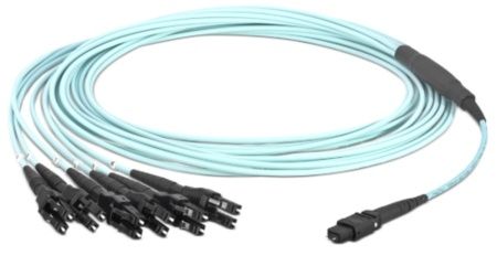
  • 10Gig migrate to 40GbE by interconnecting MTP harness cable and MTP trunk cable

Sometimes, create a simple, cost-effective migration path by installing a structured cabling system that can support your future 40GbE networking needs. Following picture uses the 8-fiber harness as shown in the diagram to connect to 10G SFP+s. This approach allows for an easy upgrade path moving from 10Gig to 40GbE connectivity.
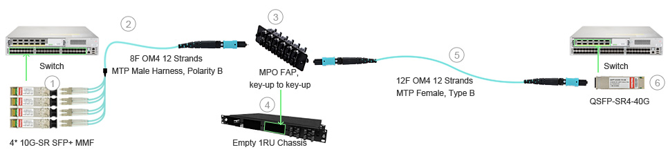
solutions_40G_pic04

Item Number FS Correlative Product Description FS Part Number
1 10GBASE-SR SFP+, 850nm 300m, MMF, LC duplex SFP-10GSR-85
2 8 Fibers OM4, 12 Strands MTP Harness Cable, MTP to LC, Type B Polarity ( MTP/ MPO, OM4/ OM3 optional. Various lengths available) OM4-LC-LC-DX-FS
3 12 Ports MTP/MPO Fiber Adapter Panel, key-up to key-up FAP-HV-12MTPUUD
4 Empty 1RU/4RU Rack Mount Fiber Patch Panel FMT1-E-FS
5 12 Fibers OM4, 12 Strands MTP Trunk Cable, Female to Female, Type B Polarity ( MTP/ MPO, OM4/ OM3 optional. Various lengths available) FS12OM4-2MTP-FF-B
6 40GBASE-SR4 QSFP+, 850nm, 150m, MMF, MPO interface QSFP-SR4-40G

Fiberstore provides wide brand compatible 40G QSFP+ SR4 transceivers and all kinds of MTP cables. Each fiber optic transceiver has been tested to ensure its compatibility and interoperability. Please rest assured to buy. For more information or quotation, please contact us via sales@fs.com.

Related Article: 40G Transceiver Module: QSFP+ Module And CFP Module

MTP Fiber Cable Solutions

Share

MTP technology with multi-fiber connectors offers ideal conditions for setting up high-performance data networks in data centers to handle future requirements. This technology makes scaling and migration to network operation with 40/100 Gigabit Ethernet easier and more efficient. There are many MTP products in the market now, such as MTP fiber cables, MTP connectors, MTP cassettes and MTP adapters. This text will tell some MTP fiber cable solutions.

Introduction of MTP Fiber System
MTPThe MTP fiber system is a truly innovative group of products that moves fiber optic networks into the new millennium. MTP fiber and MTP assemblies take their name from the MTP “Multi-fiber Termination Push-on” connector, designed and introduced as a high performance version of the MPO connectors. MTP does interconnect with the MPO connectors. Each MTP contains 12 fibers or 6 duplex channels in a connector smaller than most duplex connections in use today. MTP connectors allow high-density connections between network equipment in telecommunication rooms. It is the same size of a SC connector but since it can accommodate 12 fibers, it provides up to 12 times the density, thereby offering savings in circuit card and rack space.

Types of MTP Fiber Cable
MTP fiber cables as an important part of the multi-fiber connection system, are designed for the reliable and quick operations in data centers. The obvious benefits of these cables are less space requirements and improved scalability, providing significant space and cost savings. The MTP cables are generally used for 40GbE and 100GbE network environment.

There are two configurations for MTP cable assemblies. One is the MTP connector to MTP connector trunk cable that connects a MTP cassette to another MTP cassette. Another is MTP connector to LC or other fiber connector. Which is often called the MTP harness cable.

  • MTP Trunk Cables
    MTP trunk cables, serve as a permanent link connecting the MTP modules to each other, are available in 12-144 counts. MTP patch cords will not be used until 40G and 100G active devices are employed (with MTP interface). The ends of MTP patch cords are terminated with the customer’s choice of 12-fiber or 24-fiber MTP connectors. These high count MTP assemblies are ideal for backbone and data center applications that require a high fiber count in a limited space.

MTP Trunk Cables

  • MTP Harness Cables
    MTP harness cables, also called MTP breakout cable or MTP fanout cable, are available in 8-144 counts. The MTP harness cables work from trunk backbone assemblies to fiber rack system in the high density backbone cabling. As terminated with MTP connectors on one end and standard LC/FC/SC/ST/MTRJ connectors (generally MTP to LC) on the other end, these cable assemblies can meet a variety of fiber cabling requirements.

MTP Harness Cables

MTP Fiber Cable for 40GbE and 100GbE
Parallel optics technology has become the transmission option of choice in many data centres and labs as it is able to support 10G, 40G, and 100G transmission. Since parallel optical communication uses multiple paths to transmit a signal at a greater data rate, factory terminated MTP connectors which have either 12 fibre or 24 fibre array will support this solution.

No matter for 40G or 100G transmission, there are two MTP cable solutions. One is with the MTP trunk cable, the other is with the MTP harness cable. QSFP to QSFP uses MTP trunk cable, and QSFP to 4 SFP+ uses MTP harness cable.

  • MTP Cable 40G Solutions
    For 40GbE, a 12-fiber MTP trunk cable is used. 10G is sent along each channel/fibre strand in a send and receive direction. Here 8 of 12 fibres providing 40G parallel transmission. Shown in the following picture.

MTP 40G
For 40GbE, a 12-fiber MTP to LC harness cable is used. The IEEE ratified the 40GBASE-SR4 (MTP interface) standard that uese 4 lanes at 10G SFP+ (LC interface) per lane over multimode fiber for a total of 8 fibers. Shown in the following picture.

MTP 40G

  • MTP Cable 100G Solutions
    For 100GbE, a 24-fiber MTP trunk cable is used. 10G is sent along each channel/fibre strand in a send and receive direction. Here 20 of 24 fibres providing 100G parallel transmission. Shown in the following picture.

MTP 100G
For 100GbE, a 24-fiber MTP to LC harness cable is used. The IEEE ratified the 100GBASE-SR10 (MTP interface) standard that uese 10 lanes at 10G SFP+ (LC interface) per lane over multimode fiber for a total of 20 fibers. Shown in the following picture.

MTP 100G

MPO Solution For Gigabit Ethernet

Share

Fiberstore has designed and developed ‘quality product with affordable pricing’ for communication infrastructure solutions. This position has been achieved through our core principle of delivering maximum performance through design excellence. We built our business and products based on high product quality, trust and excellent service. We want to deliver first class solutions and a first class service to our customers.

MPO Fiber Optic Solution is a high performance, preterminated, modular system designed for high density Gigabit Ethernet Applications. It is a Plug and Play Solution that offers excellent performance and speedy installation. MPO Solution can support 10 Gb/s for link lengths up to 300 meters using laser optimized OM3 fiber, and up to 550 meters using laser optimized OM4 fiber, with a low insertion loss of 0.5dB. MPO Module employ high performance MTP adapters from US CONEC.

Fiberstore MPO end to end solution includes:

*MPO Cassette, 12 or 24 SC, LC Ports
*MPO Fanout Hydra Cable with LC or SC Connectors
*MPO to MPO Trunk Cable
*MPO Adapters
*MPO Adapter Plates
*MPO Blanking Plates (for expansion ports)
*MPO Chassis, 14 Vertical Slots, 3U, with 336 fiber terminations
*Modular Patch Panel, 3 Slots, 1U, with 72 fiber terminations

MPO Ferrule is the key component of the MPO Solution is a 12 fibre MPO (multi fibre push on) connector with a housing footprint size of a SC Simplex connector in a single floating ferrule. MPO Solution uses US Conec MTP connector, who are the market leaders. These connectors are made of precision moulded thermoplastic with metal guide pins, precise housing with asymmetrical face that allow only one orientation into the adapter, to ensure polarity is maintained along the channel.

The micro-core cables used in the MPO Cable assemblies gives about 65% reduction in the physical size of the cable per fiber when compared to traditional fiber cables.MPO Solution with 12 core LC quad adapters offers 72 LC terminations in 1U rack space using modular patch panels, and 336 LC terminations in 3U rack space using 3U Chassis. MPO Adapter Panel with 12 Core MPO connectors offers very high connectivity of 288 fibers and with 24 core MPO connectors it doubles to 576 fiber terminations in 1U rack space. Now the following is the Assemblies for Gigabit Ethernet.

MPO Cassette

MPO Cassette offers installers the choice to prepare the distribution units off site and allows for faster termination of the fiber backbone. MPO Modules can support 10Gb/s for link lengths up to 300 meters using laser optimized OM3 fiber, and up to 550 meters using laser optimized OM4 fiber, with an insertion loss of 0.5dB. MPO Module employ high performance MPO connectors for US Conec on
the rear of the units routed to the adapters of your choice in the front.

MPO Cassette

MPO Module can be installed in 1U Sliding Patch Panel and 3U Chassis. They are available with LC and SC connectors, with a choice of Singlemode, Multimode OM3 and Multimode OM4 connectivity.

MPO Trunk Cable

MPO Trunk Cable Assemblies are designed for high density application which offers excellent benefits in terms of on-site installations, time and space saving. These plug ‘n’ play solutions uses micro core cables to maximize bend radius and minimize cable weight and size. MPO Trunk Cables are factory preterminated, tested and packed along with the test reports.

Fiber Trunk Cable

Complied with the standard TIA-568C.3-2008 and YD/T1272.5-2009, it was widely used in the pre-terminated system of the IDC and blocks. This system applies to the 10G Ethernet transmissions and it is also available to the updated system for 40G/100G in the future. MPO trunk cable helps to fast installation for Data Center and other Fiber Optic environment. Its efficient plug and play structure which can significantly lower the installation and daily maintenance costs surpasses MDA, HDA and EDA regional module cassette or fan-out fiber connections. The high quality fiber optic cable and MPO accessories makes up the Linkbasic MPO Trunk cable and provides lower insertion loss and higher return loss so that it fully complied to the high speed network system.

MPO Breakout Cable

Fiberstore MPO cables are designed to offer a high degree of flexibility through available features and options, allowing each cable to be manufactured to fit the exact application. With the multitude of applications and requirements most Multi-Fiber MTP-MPO Breakout cables have. Fiberstore has established an extensive list of standard options ensuring each cable is designed and built to fit your need. Now the following is the MPO Breakout product from Fiberstore.

MPO Breakout Cable Assemblies are designed for high density applications which require high performance and speedy installations without onsite terminations. MPO breakout cables are numbered for full traceability. Available in 12 core configurations, these space saving assemblies come with either MPO Male or MPO Female Connectors on one end and LC or SC Connectors on the other end.

Fiberstore MTP MPO cables are available in single mode, multimode, and laser optimized fiber types, multiple jacket/construction types for different applications, fiber count from 2-72 fibers, and breakout style/length.

High Density MTP Cables Assemblies and MTP Cassettes

Share

IT operations are crucial to the organization for business continuity. Data centers are the central location for data interchange in IT operation of organizations and networked server farms. Ribbon fiber cables, array-based fiber connectors, and packaged breakout assemblies provide modular small form factor connectivity and enable fast, reliable interconnection of fiber optic links in high-density data center environments. Higher bandwidth requirement for 10G/40G/100G parallel optics, requirement to reduce cable size for better air flow, structured zone approach, reduction in rack space, higher density of servers and ports and reduction in installation time has brought in requirement for factory terminated high density cabling solutions. Factory terminated cable systems reduce installation time and offer scalable design and implementation. The following are MTP cable and high density MTP cassettes from FS.COM.

High Density MTP Cassette

MTP Cassette modules provide a secure transition between MTP and LC or SC discrete connectors. They are used to interconnect MTP backbones with LC or SC patching. LC to MTP and SC to MTP Fiber module provides a quick and efficient way to deploy up to 24 LC or 12 SC fiber ports in a single module. This factory terminated and tested ports are protected within the housing for reliably high performance and simply connected via 12-strand MTP ports. Modules are available in OM3, OM4 & SM fiber.

FS.COM MTP cassettes are enclosed units that contain 12 or 24–fiber factory terminated fan-outs inside. These cassettes serve to “transition” small diameter ribbon cables terminated with an MTP connector to the more common LC or SC interface used on the transceiver terminal equipment.

High Density MTP Cables

The fan-outs typically incorporate SC, LC connectors plugged into adapters on the front side of the cassette and an MTP connector plugged into an MTP adapter mounted at the rear of the cassette. One or more MTP fan-out assemblies may be installed inside the cassette to connect up to two 12-fiber ribbon cables for a total of 24 fibers. Alignment pins are pre-installed in the MTP connector located inside the cassette. Now the following is the MTP trunk cable.

Pre-connector MTP Cables are made up of 12, 24, 48 fiber LSOH jacketed micro cables terminated at both ends with MTP® Connectors (without pins). These are used as the backbone or horizontal cable interconnections. These plug and play solutions with micro core cable maximize bend radius and minimize cable weight and size. MTP Trunk Cable is factory pre-terminated, tested and packed along with the test reports. These assemblies are available in OM3, OM4 and SM fiber. Standard lengths of 5, 10, 25 meters are available. Custom lengths are also available on request. The MTP cables are packed as coils in lengths up to 50m long and on reels.

High Density MTP Breakout Cable

MTP Breakout Cable is a type of fan-out fiber optic cable ideal for data distribution to patch panels. These can be configured with 12 fiber, 24 fiber, and 48 fiber MTP connectors. They are available in both male and female MTP connectors, and also come with LC, SC, ST, and FC connectors on the fan outside.

Pre-connector MTP breakout cable assemblies are designed for high density applications which require high performance and speedy installation without onsite termination. MTP breakout cable is made up of 12 LSOH jacketed cable terminated at one end in MTP connectors, through a bifurcation unit, to SC or LC connectors terminated on 2mm OD simplex cables. These are used to connect equipment in racks to MTP cables. MTP cables are numbered for full traceability. Available in 12 core configuration, these space-saving assemblies come with either MTP Male or MTP Female Connectors on one end and LC or SC Connectors on the other end. They are available in OM3, OM4 or SM fiber in lengths of 5, 10, 25 meters, custom lengths are available on request.

We offer a wide range of MTP Cables including Trunk Cables,  MTP to LC breakout cables and MTP cassettes (or patch panels). All the assemblies are fully compliant with IEC Standards 61754-7 and TIA 604-5. We also provide Customized Service such as optional fiber counts, cable types and lengths etc.

Fiberstore MTP Product Specifications

Share

Multi-fiber technology is has exploded as a result of today’s high fiber counts and limited space requirements which Data Centers demand. Fiberstore is today’s leader in the manufacturing of MTP cables and MTP Cassette. Fiberstore engineers unique MTP solutions utilizing 12, 24, 48 and even 72 fiber MTP ferrules. Now the following is the feature and benefits of MTP cassettes and cable assemblies.

MTP cassettes and cable assemblies take their name from the MTP MPO connector, designed and introduced as a performance version of MPO connectors. MTP fiber systems are truly an innovative group of products. Each MTP connector contains 12 fibers or 6 duplex channels in a connector that is smaller than most duplex connections in use today. A 72 fiber trunk cable can be terminated with six MTP connectors and MTP connectors are manufactured specifically for multifiber loose tube or ribbon cable.

MTP connectors allow high-density connections between network equipment in telecommunication rooms. They use a simple push-pull latching mechanism for easy and intuitive insertion and removal. The ends of MTP brand connectors may be polished flat or at an 8° angle. An MTP brand connector is about the same size as a SC connector however it can accommodate 12 fibers, which provides up to 12 times the density, thereby requiring much less card and rack space.

MTP Cable

A standard MTP cassette has one port in the back with a MTP coupler awaiting connection of an MTP cable assembly that has 12 fibers in the connector. The MTP cable plugs into the back and through the adaptor. The cable connects to another MTP assembly inside the cassette that “fans out” to 12 SC or LC connections. One MTP cable can connect up 12 different ports. From there you simply plug in your patch cables.

APPLICATIONS

* Suitable for high-density switch to patching and distribution in Data Center Applications (based on 72 fiber MTP ferrule)
* Used in optical transmitters and receivers, MTP brand connectors offer up to 36 times the density of standard connectors, providing significant space and cost savings.
* Compact design addresses high fiber count applications, with small and lightweight cables ideal for use with installation space limitations.
* MTP brand cable trunks offer flexibility in changing the connector style in the patch panels. New cassettes can be installed with the new connector style on the cross-connect side of the patch panel without having to change the connector on the cable trunk.
* The MTP brand connector is the standard for delivery of 40G (in its 12 fiber version) and 100G (in either a duplexed 12 fiber cable or 24 fiber ferruled cable) using QSFP transceivers.

Multi-fiber technology will eventually replace the standards for fiber optics as we know it. Even now people are tearing out their existing infrastructure and placing MTP cassettes in their patch panels to route data for thousands of network electronics. MTP cassettes, cables, connectors and adapters are essential to backbone infrastructure. The high fiber count in one connector creates endless possibilities. Imagine a 1U rack mount patch panel that can supply data to run an entire 288-port switch. With today’s increasing demand for higher through-put, ST, SC, MTRJ, LC, FC, etc, will all be a thing of the past.

MTP Fiber Optic Cables are multi-fiber patch cords suitable for high-density back plane and PCB solutions. MTP patch cords offer up to 36 times the density (based on a 72 fiber ferrule) of traditional patch cords, providing significant space and cost savings. There are several configurations for MTP brand cable assemblies. The most popular is a MTP connector to MTP connector patch or trunk cable that connects an MTP brand cassette to another MTP brand cassette. If an MTP adapter panel is installed in a patch panel, then an MTP cable to MTP brand can be used as well.

Another configuration is MTP connectors to LC or SC fiber connector. These can be used in different applications for both back end and front end adapter panels, for instance, plug one MTP connector into the back and plug an MTP cable to LC cable into the front and have the 12 LC connections go to other equipment. If there is an MTP cassette that needs to be lit up by using a 12-fiber LC adapter panel, plug each of the 12 LC connections in the LC adapter panel. The MTP side then plugs into the back of the cassette. Increase the transfer speed with 10 Gig 50 Micron multimode cable or increase the distance the signal can travel using singlemode. Cables may be constructed of ribbon fiber, small form factor loose tube assembly cable, or subgrouped trunking cable. The options are only limited by the application.

MTP/MPO Cassettes are specially designed to reduce installation time and cost for an optical network infrastructure in the premises environment. MTP/MPO Cassettes provide secure transition between MTP/MPO and SC, LC, ST, or FC connectors. They are used to interconnect MTP/MPO backbones with LC/SC/ST/FC patching. Fiberstore MTP cassettes come in a variety of connector styles and modes. From Multimode to Singlemode, from SC to LC, MTP brand solutions can be the solution to save space, time, and energy.

MTP Trunk Cable

By plugging an MTP brand cable into the back, 12 or 24 (with quad LC) connections are being lit up . For the 24-fiber application, either one 24-fiber MTP brand cable or two 12-fiber MTP brand cables can be used. The cassette can be snapped into any standard fiber optic patch panel including both rack mount and wall mount. A RAC-1X holds three of these cassettes which could potentially contain 72 active LC connections using only three (or six) MTP brand cables. Clean up the clutter and increase your possibilities using MTP brand cassettes.

We supply MPO/MTP fiber optic cables, such as MPO MTP trunk cable, MPO/MTP breakout cable. These are available in Female to female or a male to male and male to female configurations. The male version has MTP pins. These can be made with 12 fiber MTP connectors, 24 Fiber MTP connectors, 48 Fiber MTP connector variations. We use USConec MTP fiber optic connectors for all of our MTP and MPO terminations so that the highest performance is accomplished. Many additional options and combinations are available. All multi fiber optic cables are customizable.

24 Fiber Data Center Fiber Trunking and Interconnect Solution

Share

At the heart of every enterprise is a data center that manages information that drives the business. It’s a complex, everchanging infrastructure that must be able to adapt quickly. New technologies, platforms and media, as well as end user demands for exponentially growing bandwidth pose a relentless challenge to data center managers who must keep pace with this evolution. One key to successfully navigating these challenges is to implement a solid technology migration strategy.

How can you make the best use of technology to ensure your data center can support the next three generations of equipment and successfully take you to from 1 GbE to 10GbE. The following is the intrduction of 24 Fiber System Interconnect Solution.

The 10 Gigabit Interconnect Solution, like all of the planned migration designs, employs a 24-fiber cassette with a single MPO-type connector at each end. A trunk interfaces with the rear of a 24-fiber MPO cassette that breaks out the trunk fibers into twelve duplex LC connections at the front, supporting 24 fibers per cassette. This cassette resides in a time-proven chassis which provides cable management and protection for both the MPO at the rear and LC cords at the front. Fiber enclosures are stackable and available in 1, 2, and 4 RU versions and support up to 36 duplex LCs (72 fibers) per rack unit. They can be populated all at once, or added to or upgraded a cassette at a time in the future. The Fiber enclosure also supports high density 10 Gigabit cassettes, as well as 40 and 100 GbE versions, allowing an upgrade path by changing the cassette at the front and using existing and additional 24-fiber trunks at the rear. The following is we need in the 10 Gigabit Interconnect Solution.

24 fiber trunk cables are used to connect 24 fiber 10G, 40G and 100G MPO cassettes. MPO fiber trunk cable provide the possibility to make cross-connections or inter-connections to the equipment. In case the MPO cable is connected with MPO couplers, one of the MPO connectors must have pins.

The 24 fiber MPO trunk cables are constructed from 7.5mm loose tube gel filled indoor/outdoor rated cable. The transition at each end to 3.8mm round MPO tails is protected with a free floating fiber over-molded fan-out. On both sides of the MPO connector, the tails are protected with a clear plastic protection sleeve. The sleeve is closed with a re-usable tie-wrap which can be used to strain relieve the MPO trunk to the panel or cabinet at the over-molded fan-out. For placing/pulling the trunks over longer lengths, a re-usable IP67 protection/pulling kit can be ordered separately.

trunk cable

FEATURES

Pre-terminated low loss MPO trunk cable
OM3 or OM4 bend insensitive fiber glass in an LSZH loose tube cable
Mated MPO performance for OM3 and OM4:
Attenuation ≤ 0.25 dB(max.) RL ≥ 28 dB(min)
MPO tail length 80 cm

Each product is individually tested to ensure that its performance meets or exceeds the required standard. The test results are supplied with each product.
Protection / pulling kit can be ordered separately.

The 24-fiber data center fiber trunking and interconnect solution is ideal for medium- to large-size data center customers and markets, from healthcare and finance to broadcasting and government—essentially anyone that foresees the need to update from 10- to 40/100-GbE in the future. With guaranteed support for all three applications, the ability to use all the fiber deployed, reduced cable congestion and better airflow, higher port densities in fiber panels and an easy migration scheme, the data center fiber trunking and interconnect solution with 24-fiber trunk cables offers lower future capital and operating expense.

Maintaining Polarity In Modular Fiber Optic Cassette-Based Cabling

Share

Introduction

Data centers are the central location for data interchange and are found in enterprises, government offices, schools, universities, hospitals, and other networked server farms. The ease of turning nearly any location into an information interchange hub has been enabled by the development of array-based fiber optic cabling systems. Ribbon fiber cables, array-based fiber connectors, and packaged breakout assemblies like fiber optic cassette provides modular small form factor connectivity and enable fast, reliable interconnection of fiber optic links in high-density data center environments.

Once the decision has been made to deploy array-based fiber connectivity, care must be taken to ensure the integrity of connections between the transmitting optical light source and the receiving photo detector. The matching of the transmit signal (Tx) to the receive equipment (Rx) at both ends of the fiber optic link is referred to as polarity. The objective of polarity is simple: provide transmit-to-receive connections across the entire fiber optic system in a consistent, standards-based manner.

Preterminated fiber MTP MPO optical cassettes and loose-tube or ribbon fiber backbone cables are the heart of a modular fiber system. The cassettes and cables typically support groups of full-duplex fiber connections. The challenge for the network system designer becomes one of assuring the proper polarity of these array connections from end to end.

This white paper describes the methods defined in the ratified TIA/EIA (Telecommunications Industry Association/Electronic Industries Association) standard to assure correct polarity using MPO multi-fiber array connectors, cables and cassettes.

Standards and methods:

The TR-42.8 Technical Engineering Subcommittee has developed a standard that addresses the polarity issues associated with multi-fiber array connections. (This document, TIA-568-B.1-7, is available through the Internet for purchase as a reference document.)

Currently, a new release of the TIA-568 Commercial Building Cabling Standard is under development as the TIA-568-C series of standards. The fiber-systems section of this series will be TIA-568-C.1, and will include information on array system polarity along with a description of MPO array cables, duplex patch cords, and array transitions.

Modular fiber optic cassettes:

Modular fiber optic cassettes-enclosed units containing 12- or 24-fiber factory-terminated fanouts-serve to transition small-diameter ribbon cables terminated with an MPO connector to the more-common LC or SC interfaces used on the transceiver terminal equipment. The fanouts typically incorporate SC, LC, ST-style or MT-RJ connectors plugged into adapters on the cassette’s front, and an MPO connector plugged into an MPO adapter on the cassette’s rear side.

One or more MPO fanout assemblies may be installed inside the fiber optic cassette to connect up to two, 12-fiber ribbon cables, for a total of 24 fibers. Alignment pins that are preinstalled in the MPO connector within the cassette precisely align the mating fibers in the MPO conn

ectors at either end of the array cables that plug into the cassettes.

MPO Cassette

The transition that takes place inside a fiber optic cassette, the connector keying for the cassette and the corresponding MPO array cables are all thoroughly defined for all three connectivity methods listed in the TIA standard. A common transition, factory-installed inside a cassette, is used for all three methods. The adapter mounted at the rear of a cassette defines it as either a Method A or Method B type. The only difference between the two cassette types is the orientation of the internal MPO connector with respect to the mating MPO array cable connector.

Method A cassettes make a “key up”-to-“key down” connection between the internal MPO connector and the MPO array cable connector. Method B cassettes make a “key up”-to-“key up” connection. It is important to note that a Method B cassette will not allow single mode angle-polish mated-pair connection because the angles of the mating connectors are not complementary. This prevents a Method B cassette or adapter from being used in single mode applications that require low return losses-a significant limitation.

MPO array cables:

Modular fiber optic cassettes are connected to one another with MPO to MPO ribbon backbone cables. The connectors on these cables do not contain alignment pins, but they do have mating alignment holes. Alignment pins are factory-installed in the MPO fanout connectors installed inside the fiber optic cassette.

MTP MPO fiber cables

The TIA standard defines three different 12-fiber MPO cable: Types A, B, and C. Each is used for its respective connectivity method (Methods A, B, and C).

For the Type, A array cable, the opposing connections at each end of the cable have the same fiber positions, except that one end has the key oriented facing up while the other end has the key oriented facing down.

MPO to MPO

The Type B array cable has opposing connectors with both keys oriented facing up, but the fiber positions are reversed at each end; the fiber at position 1 at one end is connected to position 12 in the connector at the opposing end.

MPO to MPO Fiber

In the Type C array cable, the key is facing up at one end and facing down at the other end. It looks like a Type-A array cable, but the Type-C cable is designed such that adjacent pairs of fibers are crossed from one end to the other. In this case, the fiber at position 1 on one end of the cable is shifted to position 2 at the other end of the cable. The fiber at position 2 on one end is shifted to position 1 at the opposite end, and so on.

Connectivity methods:

The fiber patch cord, cassette (transition) and array cable previously described are used in specific combinations to form end-to-end full-duplex fiber links. Each component of the total fiber cabling system is unique, underscoring the importance of assuring that the correct component is selected and used in the proper sequence.

Importantly, regardless of which method defined in the TIA standard you use, there must be a pair-wise flipping (A-to-B polarity swap) that takes place at some point in the link. If the pair-wise flipping does not occur in the cassette (transition), then the pair-wise flipping must occur in the duplex patch cord, or in the MPO-to-MPO array cables and/or adapters.

Conclusions:

Modular fiber optic cassette-based cabling technology offers many advantages facilitating high-performance, rapid, and error-free installation, as well as reliable, robust operation. The best way to maintain correct optical polarity in these systems is to select a standards-based approach and to adhere to it throughout an installation. The three connectivity methods defined in the TIA/EIA-56-B.1-7 standard present the guidelines for maintaining polarity using array connections.

It is in the best interest of the installer and end-user to select modular fiber optic cassette-based solutions that adhere to TIA standards. Proprietary non-standards-based solutions will not assure interoperability. In addition, those solutions may not be compatible with commercially based components designed to meet the TIA standards. Selecting modular fiber systems that comply with TIA standards can help to prevent costly troubleshooting and rework of the installed fiber cable plant. Additionally, fiber-network installers can be assured of a readily available product supply from multiple stocking supply sources with acceptable delivery lead times.

MTP/MPO System Solutions – High Density Connectivity in the Data Center

Share

MPO/MTP system solutions are steadi-ly gaining in significance. Data centers in particular have a great need for compact and flexible plug-and-play systems that are pre-measured and preterminated at the factory. MPO/MTP system solutions allow users to achieve complete end-to-end cabling in keeping with the new standard for data centers. In the IEEE 802.3 standard, 40 Gb/s and 100Gb/s were defined with MPO connector technology. The crucial factor is the insertion loss and return loss of the components. Controlled production processes and ultra-precise end-face geometry are needed to satisfy these tough requirements. With the MPO/MTP multi-fiber system, a data center is well-equipped for future transmission rates of 40 and 100Gb/s.

Benefits of deploying modular, high-density optical solutions, such as MPO-based connectivity (including MPO trunk assemblies, breakout modules and breakout harnesses) in a structured wiring architecture include 50% cable-tray space savings, 80% improvement in deployment time, and 70% bulk-cable reduction in cabinets and racks. A modular, high-density solution deployed in a structured wiring topology can easily scale to hundreds of thousands of ports and significantly reduce the time to conduct MACs in the data center, thus reducing operational costs.

So now, we have the means to cope with future growth and churn in the data center. Now, let’s address the issue of keeping this modular high-density structured cabling system in place to handle future higher-data-rate applications.

In addition to manageability and scalability, a benefit to deploying a modular, high-density MPO-based cabling system is the available migration path to increased data rates. With some consideration of performance specifications, the infrastructure can easily migrate to future higher-data-rate technologies, such as parallel optics, which will be used in 32-, 64-, and 128-Gigabit Fibre Channel; and 40- and 100-Gigabit Ethernet. In fact, by deploying an optical cabling system that meets InfiniBand 12X-QDR (120-Gbit) cable skew performance requirements of = 0.75 ns and distance specifications, the same infrastructure that is carrying serial transmission today can be easily migrated to transmit parallel-optic InfiniBand signals.

To mitigate this issue and increase the lifecycle of an optical-cabling infrastructure, deploy high-quality low-loss optical components. Low-loss MPO trunks, breakout harnesses, modules and jumpers minimize channel insertion loss and enable the cabling infrastructure to easily migrate to future higher data rates.

For example, 8-Gbit Fibre Channel will support a distance of 100 meters using OM3 fiber and a connector budget no greater than 2.4 dB. If an MPO mated pair has a maximum insertion loss of 0.5 dB, and each MTP-to-LC breakout module wasspecified at a maximum insertion loss of 0.75 dB, then theresulting maximum connector loss in the channel will be 2.75 dB.

This exceeds the recommended maximum 2.4 dB connector loss budget of 8-Gbit Fibre Channel at 100 meters, thereby reducing the supportable distance at 8-Gbit Fibre Channel; however, if low-loss components were specified into the same cable plant at 0.5-dB maximum insertion loss per MTP-to-LC breakout module and 0.35-dB maximum per MTP mated pair, then the resulting maximum connector loss in the channel will be 1.85 dB, providing support of 8-Gbit Fibre Channel beyond 100 meters.

As previously discussed, TIA-942 addresses the use of ZDAs as part of the recommended topology for datacenters. Implementing a distributed zone solution reduces pathway congestion and facilitates the implementationof MACs common in the data center environment. Implementing a zone topology can increase the number of connection points in a given channel. Using components with low-loss performance enables zone connectivity without sacrificing distance capabilities due to channel insertion loss.

MPO Fiber

Additional methods to implement zone distribution with reduced channel insertion loss include using components that are optimized for the architecture. Solutions that offer a combined MPO-based trunk assembly and breakout module can eliminate connector pairs while still offering the flexibility of zone cabling, thereby reducing total channel insertion loss. Now we introduce some MTP/MPO assemblies when you are solving MTP/MPO system.

MTP high density cabling solutions utilizes MPO (multi fiber push on) ferrule providing connection of 12 or 24 fibers. MTP provides superior physical and optical characteristics than standard MPO for precision alignment with spring loaded mechanism and guide pins. They have a removable adaptor that mates female connectors to a male connector with specially designed guide pins for orientation and maintaining polarity along the channel. The Micro-core cables used in factory terminated MTP fiber cable assemblies give 65% reduction in cable size from traditional fiber cables. Pre-connected MTP solution with 24 core LC duplex adapters offers 72 LC terminations in 1U rack space and 288 LC terminations in 4U rack space using modular patch panels.

MTP Patch Panels are scalable modular which are designed for high density Gigabit Ethernet Applications.They are used for terminating backbone cables at the Main Distribution Area (MDA) and Horizontal Distribution Area (HDA). MTP Patch Panels are available with 1U and 4U, suitable for standard 19” racks. 1U MTP Patch Panel can accommodate up to three MTP Cassettes, giving a high connectivity of 72 LC fiber terminations in it. 4U MTP Patch Panel can accommodate up to 12 MTP Cassettes, resulting in a maximum of 288 LC terminations per panel.

Fiberstore offer a wide range of MTP/MPO product including MTP and MPO trunk cables, MPO and MTP cassettes, MTP and MPO harness (breakout) cables. MTP/MPO Cable assemblies are fully compliant with IEC Standard 61754-7 and TIA 604-5. All MTP and MPO assemblies can be customize. More details, please call us or send an email to our customer services.

24-Fiber MPO 10/40/100 Gigabit Ethernet Interconnect

Share

In 2002, the IEEE ratified the 802.3ae standard for 10 GbE over fiber using duplex fiber links and vertical cavity surface emitting laser (VCSEL) transceivers. Most 10 GbE applications use duplex LC style connectors where one fiber transmits and the other receives. Standards efforts aimed at finding a cost-effective method to support next-generation speeds of 40 and 100 Gbps, and in 2010, the IEEE ratified the 802.3ba standard for 40 and 100 GbE. Similar to how transportation highways are scaled to support increased traffic with multiple lanes at the same speed, the 40 and 100 GbE standards use parallel optics, or multiple lanes of fiber transmitting at the same speed. Running 40 GbE requires 8 fibers, with 4 fibers each transmitting at 10 Gbps and 4 fibers each receiving at 10 Gbps. Running 100 GbE requires a total of 20 fibers, with 10 transmitting at 10 Gbps and 10 receiving at 10 Gbps. Both scenarios call for using high-density multi-fiber MPO style connectors.

MPO

For 40 GbE, a 12-fiber MPO connector is used. Because only 8 optical fibers are required, typical 40 GbE applications use only the 4 left and 4 right optical fibers of the 12-fiber MPO connector, while the inner 4 optical fibers are left unused as shown in Figure 1.

12-fibers

To run 100 GbE, two 12-fiber MPO connectors can be used one transmitting 10 Gbps on 10 fibers and the other receiving 10 Gbps on 10 fibers. However, the recommended method for 100 GbE is to use a 24-fiber MPO style connector with the 20 fibers in the middle of the connector transmitting and receiving at 10 Gbps and the 2 top and bottom fibers on the left and right unused as shown in Figure 2.

Knowing that 40 and 100 GbE are just around the corner,and already a reality for some, many data center managers are striving to determine which physical layer solution will support 10 GbE today while providing the best, most effective migration path to 40 and 100 GbE. While many solutions on the market recommend the use of 12-fiber multimode trunk cables between core switches and the equipment distribution area in the data center, TE Connectivity recommends and offers a better standards-based migration path with the use of 24-fiber trunk cables.

The use of 24 fiber trunk cable between switch panels and equipment is a common-sense approach. In this scenario,24-fiber trunk cables with 24-fiber MPOs on both ends are used to connect from the back of the switch panel to the equipment distribution area. For 10 GbE applications, each of the 24 fibers can be used to transmit 10 Gbps, for a total of 12 links. For 40 GbE applications, which requires 8 fibers (4 transmitting and 4 receiving), a 24-fiber trunk cable provides a total of three 40 GbE links. For 100 GbE, which requires 20 fibers (10 transmitting and 10 receiving), a 24-fiber trunk cable provides a single 100 GbE link. Why is this more advantageous than using 12-fiber trunk cables? It all comes down to a better return on investment and reduced future operating and capital expense.

As mentioned previously, 40 GbE uses eight fibers of a 12-fiber MPO connector, leaving four fibers unused. When using a 12-fiber trunk cable, those same four fibers are unused. For example, three 40 GbE links using three separate 12-fiber trunk cables would result in a total of 12 unused fibers, or four fibers unused for each trunk.

With the use of 24-fiber trunk cables, data center managers actually get to use all the fiber and leverage their complete investment. Running three 40 GbE links over a single 24-fiber trunk cable uses all 24 fibers of the trunk cable. This recoups 33% of the fibers that would be lost with 12-fiber trunk cables, providing a much better return on investment. At 100 GbE which requires 20 fibers, a total of four fibers are left unused when using either two 12-fiber trunk cables or when using a single 24-fiber trunk cable. However, additional benefits come into play for 100 GbE and 12-fiber trunk cables are not the recommended configuration for 100 GbE. Figure 3 shows the ratio of 24-fiber trunk cables to corresponding connector types for each application.

The 10 Gigabit Interconnect Solution, like all of the planned migration designs, employs a 24-fiber optical trunk with a single MPO-type connector at each end. A trunk interfaces with the rear of a 24-fiber MPO cassette that breaks out the trunk fibers into twelve duplex LC connections at the front, supporting 24 fibers per cassette. This cassette resides in a time-proven RMG chassis which provides cable management and protection for both the MPOs at the rear and LC cords at the front. Fiberstore enclosures are stackable and available in 1, 2, and 4 RU versions and support up to 36 duplex LCs (72 fibers) per rack unit. They can be populated all at once, or added to or upgraded a cassette at a time in the future. The Fiberstore enclosure also supports high density 10 Gigabit cassettes, as well as 40 and 100 GbE versions, allowing an upgrade path by changing the cassette at the front and using existing and additional 24-fiber trunks at the rear.

High Density 10 Gigabit Fiber Cassettes also utilize 24-fiber MPO trunks and support connection from 40 Gigabit switch ports that have been remotely enabled as four 10 Gigabit independent paths. MPO based QSFP ports at the switch interface with a cassette at one end of the trunk, and a break-out cassette divides these signals into duplex LC pairs at the other end. MPO cassettes have two 24-fiber MPO connectors at the rear and six 8-fiber MPOs at the front. Each cassette supports distribution of six 40 Gigabit Ethernet paths, each containing four duplex 10 Gigabit links. These cassettes are connected via standard 24-fiber MPO trunks to a pair of two 2×12 LC duplex cassettes at the other end of the trunk. This pair of cassettes maintains fiber paths and polarity and provides proper fiber mapping from transmit at one end to receive at the other over a total of twenty-four 10 Gigabit paths.

Fiberstore supply 12, 24, 48, 72, 96 and 144 fiber core constructions with OM1, OM2, OM3 or OM4 fiber trunk cable, these trunk cable assemblies are composed of high quality LSZH jacketed fiber optic cables, connecting equipment in racks to MTP/MPO backbone cables. All kinds of MTP MPO cable length can be customized, meanwhile we also provide 40G/100G MTP/MPO cable solution.

Fiber Transmissions at Higher-speed Ethernet

Share

When moving to 40/100GbE, the most important difference in backbone and horizontal multimode applications is the number of fiber strands. 40GBASE-SR4 uses 4 strands to transmit and receive for a total of 8 strands. 100GBASE-SR10 uses 10 lanes to transmit and receive for a total of 20 strands. SMF remains a 2-strand application and although the fiber is less expensive, SMF optics and electronics can be 10x more expensive. In data centers and backbones, it may be possible to have 8 or 20 individual strands of fiber. However, those strands may take disparate paths from one end to the other and this can cause delay skew (known as bit skew) resulting in bit errors. For this reason, the 40/100GbE standards are written around fiber optic trunk assemblies that utilize a MPO or MTP multi-fiber array connector. In these assemblies, all strands are the same length. Also referred to as “parallel optics,” this construction minimizes bit/delay skew, allowing the receive modules to receive each fibers information at virtually the same time.

MPO (Multi-fiber push-on) and MTP (Mechanical Transfer Push-on) are available in both 12 and 24 strand termination configurations used at the end of a trunk assembly. The MTP design is an improved version of the MPO. The patented MTP connector is a ruggedized version with elliptical shaped, stainless steel alignment pin tips to improve insertion guidance and reduce guide hole wear. The MTP connector also provides a ferrule float to improve mechanical performance by maintaining physical contact while under an applied load. MPO MTP trunks also support for the 10GBASE-SR/SX applications although only two fiber strands are used. In this case trunks are connected to cassettes and/or hydra assemblies, which break out the multiple fibers into two-strand connections (typically LC or SC).

MPO Cabling

The second difference in high-speed fiber configurations is polarity. For 2-strand applications such as 10GbE transmission, managing polarity is as simple as reversing the strands somewhere over the channel. This is true if the channel is constructed of individual strands or is part of a trunk assembly. In trunk assemblies, which have historically been 12-strand, there are three suggested polarity methods in the standards (as shown in the following table).

As shown above, 2-strand application polarity managing is relatively easy. When migrating from 2-strand to multi-strand parallel optics, it is important to note which polarity method was selected to assure that the correct assemblies are purchased for higher speeds. All polarity methods can be converted from 2-strand to 12-strand applications.

40G

It is important to note that these polarity methods are suggested in the standards, not mandated. However, the mandate does state that a polarity method should be established and maintained throughout all fiber channels, mapping the transmit strand from one end to the receive strand at the other. This does not change for higher fiber count transmissions, with the exception that more strands are involved. To better visualize the transmission for multistrand applications, consider the following diagrams:

40GBASE-SR uses 8 strands of a 12-strand MPO/MTP trunk cable, (4 to transmit and 4 to receive). The middle 4 strands in the MPO/MTP connector remain dark. The interface on equipment will accept an MPO/MTP array connector rather than a traditional LC.

100GbE has three approved methods for transmission including one 24-strand (shown left) or two 12-strand trunks either “over and under” or “side-by-side” (shown right- Side-by-side configuration is not shown). The transmission uses 10 strands to transmit and 10 to receive leaving the outer unused strands dark. It is also possible to connect two 1- strand trunks via a “Y” assembly that converts two 12-strand trunk assemblies to one 24-strand assembly. Polarity must also be considered regardless of the method chosen and supported by the electronics.

The new MTP cables can bridge legacy 1Gbps/10Gbps networks over to 40Gbps/100Gbps networks, and can act as the trunk line on a network backbone. Since a single fiber cable can connect up to 24 devices, fewer cables are needed, cutting down on installation labor. The high-density, small form factor also saves space and improves air flow. With its push-pull release mechanism, the MTP connector is easy to engage and disengage.

FiberStore provide a wide range of MTP/MPO products including single mode or multimode MPO and MTP fiber cable. High density MTP/MPO trunk cables with up to 144 fibers in a single cable. Fiberstore also offer wide range of MTP MPO cassette. The standard cassettes can accommodate 12 and 24 port configurations. Different sizes of cassettes are available. Available in all fibermodes and connector options. Custom Options available including MPO MTP taps and MTP/MPO Silitter combinations.