Tag Archives: 40G/100G

What are OM1, OM2, OM3 and OM4?

Share

There are different types of fiber optic cable. Some types are single-mode, and some types are multimode. Multimode fibers are described by their core and cladding diameters. Usually the diameter of the multimode fiber is either 50/125 µm or 62.5/125 µm. At present, there are four kinds of multi-mode fibers: OM1, OM2, OM3 and OM4. The letters “OM” stand for optical multimode. Each type of them has different characteristics.

Standard

Each “OM” has a minimum Modal Bandwidth (MBW) requirement. OM1, OM2, and OM3 fiber are determined by the ISO 11801 standard, which is based on the modal bandwidth of the multimode fiber. In August of 2009, TIA/EIA approved and released 492AAAD, which defines the performance criteria for OM4. While they developed the original “OM” designations, IEC has not yet released an approved equivalent standard that will eventually be documented as fiber type A1a.3 in IEC 60793-2-10.

Specifications

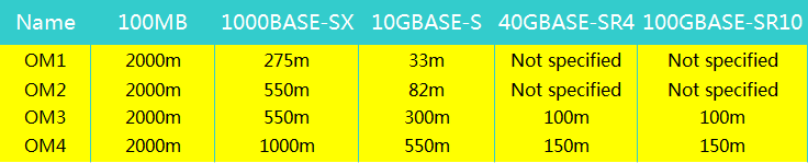
  • OM1 cable typically comes with an orange jacket and has a core size of 62.5 micrometers (µm). It can support 10 Gigabit Ethernet at lengths up 33 meters. It is most commonly used for 100 Megabit Ethernet applications.
  • OM2 also has a suggested jacket color of orange. Its core size is 50µm instead of 62.5µm. It supports 10 Gigabit Ethernet at lengths up to 82 meters but is more commonly used for 1 Gigabit Ethernet applications.
  • OM3 fiber has a suggested jacket color of aqua. Like OM2, its core size is 50µm. It supports 10 Gigabit Ethernet at lengths up to 300 meters. Besides OM3 is able to support 40 Gigabit and 100 Gigabit Ethernet up to 100 meters. 10 Gigabit Ethernet is its most common use.
  • OM4 also has a suggested jacket color of aqua. It is a further improvement to OM3. It also uses a 50µm core but it supports 10 Gigabit Ethernet at lengths up 550 meters and it supports 100 Gigabit Ethernet at lengths up to 150 meters.

OM1, OM2, OM3 and OM4 multi-mode fiber

Differences

There are several differences between four kinds of multi-mode fiber, and we can see them clearly from the table below:
OM1, OM2, OM3 and OM4 multi-mode fiber

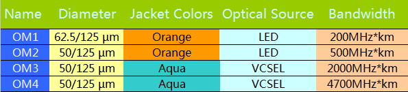
  • Diameter: The core diameter of OM1 is 62.5 µm , however, core diameter of the OM2, OM3 and OM4 is 50 µm.
  • Jacket Color: OM1 and OM2 MMF are generally defined by an orange jacket. OM3 and OM4 are usually defined with an aqua jacket.
  • Optical Source: OM1 and OM2 commonly use LED light source. However, OM3 and OM4 usually use 850 nm VCSELs.
  • Bandwidth: At 850 nm the minimal modal bandwidth of OM1 is 200MHz*km, of OM2 is 500MHz*km, of OM3 is 2000MHz*km, of OM4 is 4700MHz*km.

OM3 & OM4 are Superior to OM1&OM2

10G OM3Both OM1 and OM2 work with LED based equipment that can send hundreds of modes of light down the cable, while OM3 and OM4 are optimized for laser (eg. VCSEL) based equipment that uses fewer modes of light. LEDs can not be turned on/off fast enough to support higher bandwidth applications, while VCSELs are capable of modulation over 10 Gbit/s and are used in many high speed networks. For this reason, OM3 and OM4 are the only multi-mode fibers included in the 40G and 100G Ethernet standard. Now OM1 and OM2 are usually used for 1G which are not suitable for today’s higher-speed networks. OM3 and OM4 are used for 10G mostly at present. But in the future, since OM3 and OM4 can support the 40G and 100G, which may make them the tendency.

Related article: Singl-mode vs. Multimode Fiber Cable

MTP Fiber Cable Solutions

Share

MTP technology with multi-fiber connectors offers ideal conditions for setting up high-performance data networks in data centers to handle future requirements. This technology makes scaling and migration to network operation with 40/100 Gigabit Ethernet easier and more efficient. There are many MTP products in the market now, such as MTP fiber cables, MTP connectors, MTP cassettes and MTP adapters. This text will tell some MTP fiber cable solutions.

Introduction of MTP Fiber System
MTPThe MTP fiber system is a truly innovative group of products that moves fiber optic networks into the new millennium. MTP fiber and MTP assemblies take their name from the MTP “Multi-fiber Termination Push-on” connector, designed and introduced as a high performance version of the MPO connectors. MTP does interconnect with the MPO connectors. Each MTP contains 12 fibers or 6 duplex channels in a connector smaller than most duplex connections in use today. MTP connectors allow high-density connections between network equipment in telecommunication rooms. It is the same size of a SC connector but since it can accommodate 12 fibers, it provides up to 12 times the density, thereby offering savings in circuit card and rack space.

Types of MTP Fiber Cable
MTP fiber cables as an important part of the multi-fiber connection system, are designed for the reliable and quick operations in data centers. The obvious benefits of these cables are less space requirements and improved scalability, providing significant space and cost savings. The MTP cables are generally used for 40GbE and 100GbE network environment.

There are two configurations for MTP cable assemblies. One is the MTP connector to MTP connector trunk cable that connects a MTP cassette to another MTP cassette. Another is MTP connector to LC or other fiber connector. Which is often called the MTP harness cable.

  • MTP Trunk Cables
    MTP trunk cables, serve as a permanent link connecting the MTP modules to each other, are available in 12-144 counts. MTP patch cords will not be used until 40G and 100G active devices are employed (with MTP interface). The ends of MTP patch cords are terminated with the customer’s choice of 12-fiber or 24-fiber MTP connectors. These high count MTP assemblies are ideal for backbone and data center applications that require a high fiber count in a limited space.

MTP Trunk Cables

  • MTP Harness Cables
    MTP harness cables, also called MTP breakout cable or MTP fanout cable, are available in 8-144 counts. The MTP harness cables work from trunk backbone assemblies to fiber rack system in the high density backbone cabling. As terminated with MTP connectors on one end and standard LC/FC/SC/ST/MTRJ connectors (generally MTP to LC) on the other end, these cable assemblies can meet a variety of fiber cabling requirements.

MTP Harness Cables

MTP Fiber Cable for 40GbE and 100GbE
Parallel optics technology has become the transmission option of choice in many data centres and labs as it is able to support 10G, 40G, and 100G transmission. Since parallel optical communication uses multiple paths to transmit a signal at a greater data rate, factory terminated MTP connectors which have either 12 fibre or 24 fibre array will support this solution.

No matter for 40G or 100G transmission, there are two MTP cable solutions. One is with the MTP trunk cable, the other is with the MTP harness cable. QSFP to QSFP uses MTP trunk cable, and QSFP to 4 SFP+ uses MTP harness cable.

  • MTP Cable 40G Solutions
    For 40GbE, a 12-fiber MTP trunk cable is used. 10G is sent along each channel/fibre strand in a send and receive direction. Here 8 of 12 fibres providing 40G parallel transmission. Shown in the following picture.

MTP 40G
For 40GbE, a 12-fiber MTP to LC harness cable is used. The IEEE ratified the 40GBASE-SR4 (MTP interface) standard that uese 4 lanes at 10G SFP+ (LC interface) per lane over multimode fiber for a total of 8 fibers. Shown in the following picture.

MTP 40G

  • MTP Cable 100G Solutions
    For 100GbE, a 24-fiber MTP trunk cable is used. 10G is sent along each channel/fibre strand in a send and receive direction. Here 20 of 24 fibres providing 100G parallel transmission. Shown in the following picture.

MTP 100G
For 100GbE, a 24-fiber MTP to LC harness cable is used. The IEEE ratified the 100GBASE-SR10 (MTP interface) standard that uese 10 lanes at 10G SFP+ (LC interface) per lane over multimode fiber for a total of 20 fibers. Shown in the following picture.

MTP 100G

The 100G Industry Chain Still Needs To Improve

Share

With the outbreak of emerging businesses such as high-definition video, social games, cloud computing and Internet of things, explosive growth of Internet content, so that the needs of next generation of Ethernet is increasing. Although the 40G/100G standards have been promulgated, the demand is also constantly stimulated, operators also verified the 100G with a commercial ability, but its scale popularity seems to have a distance, especially for 100G. What is the reason hindering the popularization, in technically what need to improve? When can really go the way of 100G?

The too high cost hinders 100G popularity And market maturity needs 3 years

China Telecom Technology Committee Director Wei Leping said, to achieve the scale of promotion, the cost of 100G applications should be controlled at as 5-6 times as the cost of 10G, there is a certain distance currently. Ruijie experts said, from the point of the cost of fiber optic transceiver, 100G module costs several times higher than the cost of 10G transceiver. It also requires the upstream and downstream of the industrial chain complement each other, continue working hard in chip integration, integration of optical module miniaturization and system design, to achieve cost reduction of the overall product. In addition, the architecture design of network manufacturers are also important factors, the role of the scale cost reduction such as supporting cables, wiring and tools also can not be ignored.

Overall, the 40G and 100G markets are in the early stage of market, but in contrast, the growth rate of 40G is faster than 100G, for example, Ruijie has made a considerable number of 40G commercial cases.

While the 100G standard has completed, but there are still not small challenges in the core of the optical module/high-speed signal processing technology, 100G commercial products also just launched by manufacturers. Therefore, experts believe that, the mature of 100G market is expected to take at least three years.

As we all know, the optical module technology cost is the key of the whole 100G system cost. But the 100G optical module devices are mainly controlled by foreign companies, although there are some Chinese enterprises introduced the 100G optical modules, but the quantity is too small, which virtually increases the 100G system cost.

There are still defects in technical and need to further improve the industrial chain

The 100G industrial chain including chip, optical devices, router to optical transmission system, and even the deployment, but the current situation is that, in the fiber optic module, the high-end core technology are basically controlled by foreign countries. Many experts said, the Chinese module makers have not domestic semiconductor chip production technology,  no continuous wavelength tunable lasers and high-end modulator chip, the manufacturer can do 100G optical devices is rare. Although there are more and more manufacturers to join this camp now, but many companies just re-processing of imported products, the lack of core technology, so there is no competition.

In addition to the short supply and not enough maturity of chip, optical devices and so on, some experts pointed out, the 100G industry chain supporting needs to be further improved, not only because the 100G optical network construction was just started, but also because the development of the 100G still faces challenges from the technology and market, for example, still exist cognitive gap in the line, construction, adjusting and testing, industry chain parties need to work together.

40/100G complement each other

Demand determines the market. From the current applications, in addition to some large data centers, the vast majority applications do not need the 100G bandwidth now, the bandwidth of 40G is sufficient; while the 40G products are more cost-effective than 100G products, and is expected to last a period of time, so the 40G products develop more smoothly than 100G in the moment. But apparently, the scene requires higher performance is relatively urgent demand for 100G, typical scenes such as super computing, cluster computing, etc. In the future, 40G and 100G will complement each other, service users in different application scenarios.