Tag Archives: OM4 Fiber

Why Demand for Ultra High Density Fiber Optic Enclosures?

Share

Increased demand for data to support streaming media and the increased use of mobile broadband communications has resulted in dramatic advances in network switching infrastructure over the past 10 years. Furthermore, this demand is expected to continue at a record pace. Since the transition from copper to fiber as the standard for high-performance data communications and the number of fibers used to support emerging standards, such as 100GBit/s Ethernet, for the individual connection has increased, to choose higher density fiber optic enclosures is certainly innate.

Currently, network switching products are available with port line cards that use more than 1,000 OM3 fiber and OM4 fibers per chassis switch for 10G duplex fiber applications. Future 40/100Gb switches are projected to use more than 4,000 fibers per chassis where parallel optics is used. These high fiber count requirements demand high-density cable and hardware solutions that will reduce the overall footprint and simplify cable management and connections to the electronics.

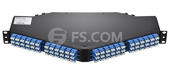
Fiberstore’s new FMT1-4FAP-LCDX series product allows customers to migrate from a standard 2U fiber enclosure that will house 3 adapter panels for a maximum of 72 LC connectors to our new 96 ports fiber optic enclosures that will hold 4 adapter panels in a 1U space allowing a maximum of 96 LC connectors! This gives users 33% (or 24 more) more LC connections in a 1U enclosure versus a 2U enclosure.

96 Ports Fiber Optic Enclosure

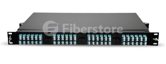
Besides, you can get more density by utilizing our MPO/MTP to LC cassette module. Our HDSM-12MTP/MPO rack mountable MTP cassette is loaded with 72 LC duplex connectors, giving it 144 ports total within 1U of rack space. And this 1U enclosures can be mounted vertically so you can match every blade in the switch to each enclosure. This high-density MTP cassette is constructed of light weight, yet durable, rolled steel. The shallow depth of the Ultra Panel makes it suitable for copper racking systems or telecommunication rack infrastructure.

144 Ports Fiber Optic Enclosure

With the rise in demand for higher bandwidth and faster download speeds, FS.COM high-density fiber optic enclosures were designed to keep pace with these requirements. In addition, both of these unique fiber optic enclosure lines offer installers easy terminations, and performance-driven connectivity. Couple that with FS.COM’s proven fiber optic cable, in particular, our HD push-pull tab patch cables, customers can expect an exceptional solution to fit their high-density needs.

WBMMF – Next Generation Duplex Multimode Fiber in the Data Center

Share

Enterprise data center and cloud operators use multimode fiber for most of their deployments because it offers the lowest cost means of transporting high data rates for distances aligned with the needs of these environments. The connections typically run at 10G over a duplex multimode fiber pair—one transmit (Tx) fiber and one receive (Rx) fiber. Upgrading to 40G and 100G using MMF has traditionally required the use of parallel ribbons of fiber. While parallel transmission is simple and effective, continuation of this trend drives higher cost into the cabling system. However, a new generation of multimode fiber called WBMMF (wideband multimode fiber) is on the way, which can enable transmission of 40G or 100G over a single pair of fibers rather than the four or ten pairs used today. Now, let’s get close to WBMMF.

What Is Wideband Multimode Fiber?
WBMMF is a new multimode fiber type under development that will extend the ability of conventional OM4 fiber to support multiple wavelengths. Unlike traditional multimode fiber, which supports transmission at the single wavelength of 850 nm, WBMMF will support traffic over a range of wavelengths from 850 to 950 nm. This capability will enable multiple lanes of traffic over the same strand of fiber to transmit 40G and 100G over a single pair of fibers and to drastically increase the capacity of parallel-fiber infrastructure, opening the door to 4-pair 400GE and terabit applications. Multimode fiber continues to provide the most cost-effective platform for high bandwidth connectivity in the data center, and with the launch of the WBMMF solution, that platform has been extended to support higher speeds with fewer fibers and at greater distances.

Wideband Multimode Fiber

What Is the Technology Behind WBMMF?
WBMMF uses short wavelength division multiplexing (SWDM) to significantly increase its transmission capacity by four times. WDM technology is well known for its use in single-mode transmission, but has only recently been adapted for use with vertical cavity surface-emitting lasers (VCSELs), which have been proven in high-speed optical communications and are widely deployed in 10G interconnection applications. SWDM multiplexes different wavelengths onto duplex MMF utilizing WDM VCSEL technology. By simultaneously transmitting four VCSELs, each operating at a slightly different wavelength, a single pair WBMMF can reliably transfer 40G (4x10G) or 100G (4x25G). The use of SWDM then enables WBMMF to maintain the cost advantage of multimode fiber systems over single mode fiber in short links and greatly increases the total link capacity in a multimode fiber link.

SWDM WBMMF

Why Does WBMMF Make Sense?
In order to increase transmission speeds up to 10G or 25G, transceiver vendors simply increased the speed of their devices. When 40G and 100G standards were developed, transmission schemes that used parallel fibers were introduced. This increase in fiber count provided a simple solution to limitations of the technology available at the time. It was accepted in the industry and allowed multimode links to maintain a low cost advantage. However, the fiber count increase was not without issues. At some point, simply increasing the number of fibers for each new speed became unreasonable, in part because the cable management of parallel fiber solutions, combined with the increasing number of links in a data center, becomes very challenging. Please see the picture below. Usually, 40G is implemented using eight of the twelve fibers in an MPO connector. Four of these eight fibers are used to transmit while the other four are used to receive. Each Tx/Rx pair is operating at 10G. But if we use WDMMF, two fibers are enough. Each Tx/Rx pair can transmit 40G by simultaneously transmitting four different wavelengths. This enables at least a four-fold reduction in the number of fibers for a given data rate, which provides a cost-effective cabling solution for data center.

Parallel fibers vs WBMMF

Conclusion
WBMMF is born at the right moment to meet the challenges associated with escalating data rates and the ongoing need to build cost-effective infrastructure. Besides, WBMMF will support existing OM4 applications to the same link distance. Optimized to support wavelengths in the 850 nm to 950 nm range to take advantage of SWDM, WBMMF ensures not only more efficient support for future applications to useful distances, but also complete compatibility with legacy applications, making it an ideal universal medium that supports not only the applications of the present, but also those of the future.

Related Article: OM5 Multimode Fiber FAQs

Overview of 16 Gbps Fiber Channels

Share

Offering considerable improvements from previous FC speeds, 16 Gbps FC uses 64b/66b encoding, retimers in modules, and transmitter training. Doubling the throughput of 8 Gbps to 1,600 Mbps, it uses 64b/66b encoding to increase the efficiency of the link. 16 Gbps FC links also use retimers in the optical modules to improve link performance characteristics, and electronic dispersion compensation and transmitter training to improve backplane links. The combination of these technologies enables the 16 Gbps FC to provide some of the highest throughput density in the industry, making data transfers smoother, quicker, and cost-efficient.

Although 16 Gbps FC doubles the throughput of 8 Gbps FC to 1600MBps, the line rate of the signals only increases to 14.025 Gbps because of a more efficient encoding scheme. Like 10 Gbps FC and 10 Gigabit Ethernet (GbE), 16 Gbps FC uses 64b/66b encoding, that is 97% efficient, compared to 8b/10b encoding, that is only 80% efficient. If 8b/10b encoding was used for 16 Gbps FC, the line rate would have been 17 Gbps and the quality of links would be a significant challenge because of higher distortion and attenuation at higher speeds. By using 64b/66b encoding, 16 Gbps FC improves the performance of the link with minimal increase in cost.

To remain backward compatible with previous Fiber Channel speeds, the Fiber Channel application specific integrated circuit (ASIC) must support both 8b/10b encoders and 64b/66b encoders.

As seen in Figure 2-1, a Fiber Channel ASIC that is connected to an SFP+ module has a coupler that connects to each encoder. The speed-dependent switch directs the data stream toward the appropriate encoder depending on the selected speed. During speed negotiation, the two ends of the link determine the highest supported speed that both ports support.

The second technique that 16 Gbps FC uses to improve link performance is the use of retimers or Clock and Data Recovery (CDR) circuitry in the SFP+ modules. The most significant challenge of standardizing a high-speed serial link is developing a link budget that manages the jitter of a link. Jitter is the variation in the bit width of a signal due to various factors, and retimers elliminate most of the jitter in a link. By placing a retimer in the optical modules, link characteristics are improved so that the links can be extended for optical fiber distances of 100 meters on OM3 fiber. The cost and size of retimers has decreased significantly so that they can now be intergrated into the modules for minimal cost.

The 16 Gbps FC multimode links were designed to meet the distance requirements of the majority of data centers. Table 2-2 shows the supported link distances over multimode and single-mode fiber 16 Gbps FC was optimized for OM3 fiber and supports 100 meters. With the standardization of OM4 fiber, Fiber Channel has standardized the supported link distances over OM4 fiber, and 16 Gbps FC can support 125 meters. If a 16 Gbps FC link needs to go farther than these distances, a single-mode link can be used that supports distances up to 10 kilometers. This wide range of supported link distances enables 16 Gbps FC to work in a wide range of environments.

Another important feature of 16 Gbps FC is that it uses transmitter training for backplane links. Transmitter training is an interactive process between the electrical transmitter and receiver that tunes lanes for optimal performance. The 16 Gbps FC references the IEEE standards for 10GBASE-KR, which is known as Backplane Ethernet, for the fundamental technology to increase lane performance. The main difference between the two standards is that 16 Gbps FC backplanes run 40% faster than 10GBASE-KR backplanes for increased performance.

Fiberstore introduces it’s new OM4 Laser-Optimized Multimode Fiber (LOMMF) “Aqua” cables, for use with 40/100Gb Ethernet applications. These new technology, 50/125um, LC/LC Fiber Optic cables, provide nearly three times the bandwidth over conventional 62.5um multimode fiber, with performance rivaling that of Singlemode cable, at a much reduced cost. LOMMF cable allows 40/100Gb serial transmission over extended distances in the 850nm wavelength window, where low-cost Vertical Cavity Surface Emitting Lasers (VCSELs) enable a cost-effective, high-bandwidth solution. OM4 fiber optic patch cord is ideally suited for LAN’s, SAN’s, and high-speed parallel interconnects for head-ends, central offices, and data centers. Tripp Lite warrants this product to be free from defects in material and workmanship for Life. Now the following is the OM4 fiber from Fiberstore.

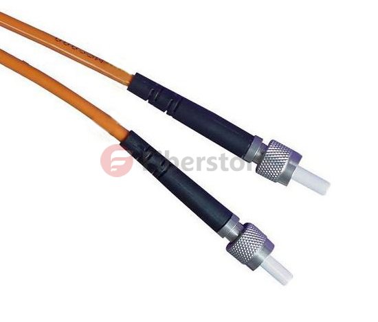
OM4 SC to SC fiber patch cord feature an extremely high bandwidth–4700MHz*km, more than any other mode. They support 10GB to 550 meters and 100GB to 125 meters. These cables are suitable for high-throughput applications, such as data storage. These cables are fully (backwards) compatible with 50/125 equipment as well as with 10 gigabit Ethernet applications. These connectors utilize a UPC (Ultra Physical Contact) polish which provides a better surface finish with less back reflection. With the OM4 cables, you can use longer lengths than OM3 cables while still having an excellent connection.

We offer a huge selection of single and multimode patch cords for multiple applications: mechanical use, short in-office runs, or longer runs between and within buildings, or even underground. Gel-free options are available for less mess, and Bend Insensitive cables for minimizing bend loss, which can be difficult to locate and resolve.

Related Article:  Which Patch Cable Should I Choose for My Optical Transceiver?
The Progress of Multimode Fiber

Share

In 1976, Corning developed 50/125μm by the graded-index multimode fiber and 1983 by Lucent Bell Labs developed 62.5/125μm graded-index multimode fiber, they are two larger amount of Multimode Fiber. The cladding diameter and mechanical properties of these two fibers are same, but different transmission characteristics. They can provide such as Ethernet, Token Ring and FDDI protocols specified in the standard distance required bandwidth, and it can be upgraded to Gb/s rate.

The new multimode fiber standard grades issued by ISO / IEC 11801, Multimode fiber is divided into four categories, OM1, OM2, OM3, OM4. OM1 and OM2 refer to traditional 62.5/125μm and 50/125μm multimode fiber. OM3 and OM4 refer to the new Gigabit 50/125μm multimode fiber.

62.5/125μm Graded-index Multimode fiber(OM1,OM2)

Common 62.5/125μm graded-index multimode fiber is the IEC-60793-2 fiber optic products specification Alb type. As the core diameter and a numerical aperture of 62.5/125μm fiber is greater, which has a strong anti-concentrating ability and bending characteristics, especially in the 20th century, before the mid-1990s, the lower the rate of the LAN, less demanding on the fiber bandwidth, thus making this fiber to obtain the most widely used, becomes 20 years between the mid-1980s to the mid-1990s mainstream products in most countries data communications fiber market. Belong OM1 and OM2 fiber types of Alb full power injection (OFL) bandwidth respectively 200/500MHz.km (850/1300nm) 500/500MHz.km (850/1300nm).

Now you can see the follow products about 62.5 Multimode Fiber

Duplex OM1 62.5/125 Dia2.5mm Fiber Patch Cable

SMA905- SMA905 Duplex OM1 62.5/125 Dia2.5mm Fiber Patch Cable from Fiberstore

50/125μm graded-index multimode fiber(OM1,OM2)

Common 50/125μm OM2 Fiber graded-index multimode fiber is the IEC-60793-2 fiber optic products specification Ala.1 type. Historically, in order to reduce as much as possible the cost of the LAN system, widely used inexpensive LED as the light source, rather than expensive LD. Since the LED output power is low, the divergence angle is much larger than LD, while the core diameter and a numerical aperture of 50/125μm multimode fiber are relatively small, is not conducive to efficient coupling with the LED, as large core diameter and numerical aperture of 62.5/125μm (Alb class) fiber enables more light power coupled into the fiber link to, therefore, 50/125μm graded-index multimode fiber in the mid-90s as good as 62.5/125μm (Alb class) that is widely used fiber.

Since the 20th century, a local area network developed up to lGb / s rate, it didn’t meet the requirement 62.5/125μm OM1 Fiber bandwidth with LED light source. Compared with 62.5/125μm multimode fiber, 50/125μm multimode fiber core diameter and a numerical aperture smaller, 50/125μm gradient in the number of multi-mode fiber conduction mode refractive index of about 62.5/125μm multimode fiber conduction mode 1/2.5, thus effectively reducing the modal dispersion of a multimode optical fiber, such that the bandwidth is significantly increased production costs .50/125μm multimode optical fiber is reduced to about 1/3. So make it again been widely used. IEEE802.3z Gigabit Ethernet standard provides 50/125μm multimode and 62.5/125μm multimode fiber can be used as a transmission medium using Gigabit Ethernet. But for the new network is generally preferred 50/125μm multimode fiber. Belong OM1 and OM2 fiber types are Ala. 1 full power injection (OFL) bandwidth respectively 200/500MHz.km (850/1300nm) and 500/500MHz.km (850/1300nm)

OM3 Fiber

Traditional OM1 and OM2 multimode fiber from the standard mode and design are based LED, as the operating wavelength of 850 nm, a low price VCSEL (Vertical Cavity Surface Emitting Laser) and the emergence of wide application, 850nm importance window increased. VCSEL can be lower than the price of long-wavelength lasers to improve network speed to the user. 50/125μm multimode fiber has a higher bandwidth 850nm window, low price VCSEL can support longer transmission distances for Gigabit Ethernet protocol, and the high rate support longer distances. With the improvement of network speed and size, modulation rates up to 10Gb/s short-wavelength VCSEL laser light sources become one of the high-speed network. Since the difference between the two light-emitting devices, optical fibers must transform itself to adapt to changes in light. In order to meet the needs of 10 Gb / s transfer rate, the International Organization for Standardization / International Electrotechnical Commission (ISO/IEC) and the Telecommunications Industry Alliance (TIA) joint drafting of a new generation of 50 μm core multimode fiber standard. ISO/IEC in the new multi-mode fiber grade they will develop a new generation of multi-mode fiber is zoned 0M3 category (IEC standard A1a.2)

OM4 Fiber

OM4 fiber is optimized for the 50μm core multimode fiber, currently, the OM4 (IEC standard A1a.3) criteria is actually an upgraded version of an OM3 multimode fiber. Compared with standard OM3 OM4 fiber, fiber bandwidth indicators just do upgrade. That OM4 standards are made to improve the 850nm wavelength effective modal bandwidth (EMB) and the full bandwidth of the injection (OFL) compared to OM3 fiber.