Author Archives: Alice.Gui

250um Bare Fiber vs. 900um Tight Buffer Fiber

Share

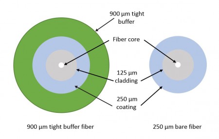
Ever wonder the difference between loose-tube 250um bare fiber and tight-buffered 900um fiber? Loose-tube 250um and tight-buffered 900um fiber cables actually start with the same 250um bare fibers that feature the same size fiber core (i.e., 50um for multimode and 9um for singlemode), 125um cladding and soft 250um coating. The difference between these two cables all lies in the cable construction.

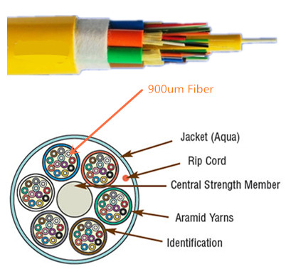
900um Fiber Adds an Additional Layer
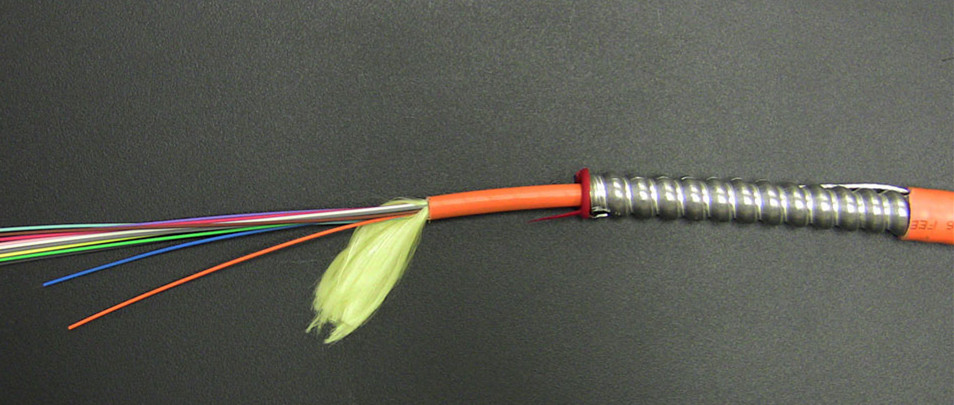
Tight-buffered 900um fiber includes an additional 900um layer of hard plastic over the 250um fibers for protection. Within the cable, several of these color-coded 900um tight buffered fibers are situated around a central strength member and then covered with Kevlar or aramid yarn for protection, a rip cord and then the jacket.

250um Bare Fiber vs. 900um Tight Buffer Fiber
Tight-buffered 900um fiber cable comes in various fiber counts that typically range from 2 to 144 fibers, with larger fiber counts featuring fiber subunits of 6 or 12 fibers within the cable. For example, a 144-fiber cable usually has twelve 12-fiber subunits while a 36-fiber cable could have six 6-fiber subunits or three 12-fiber subunits.

900um fiber cable

250um Fiber Is Enclosed in Tubes
Loose-tube 250um fiber places up to 12 bare 250um fibers inside a flexible plastic tube, which are also color coded and situated around a central strength member with Kevlar or aramid yarn for protection. Buffered loose-tube cables feature an outer waterblocking tape around the tubes, beneath the outer jacket.

 250um fiber cable
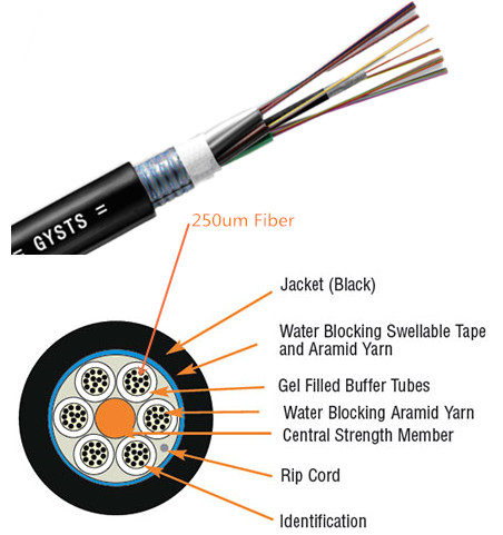
The tubes themselves are gel-filled to prevent water migration, or they are available with a dry waterblocking technology—sometimes referred to as gel-free cable. Both of these materials are vital to prevent water from migrating into the tubes and potentially freezing, expanding and breaking the fiber. Dry waterblocking technology significantly reduces installation time by eliminating the need to clean off the gel prior to termination.

Loose-tube 250um fiber cable comes in various fiber counts that typically range from 6 to 144. With the exception of a 6-fiber cable, the fibers are grouped into sets of 12 for maximum density. Speaking of density, without the 900um plastic coating, loose-tube 250um fiber cables are less than half the size of 900um fiber cables—1.4 inch (35.6 mm) for a 144-fiber tight buffer cable and only 67 inch (17 mm) for an outdoor 144-fiber loose-tube cable.

From Outdoor to Indoor Applications
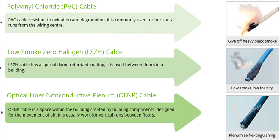
Generally speaking, tight-buffered 900um fiber cables are used for indoor applications, including intra-building riser and plenum applications and in the data center. Loose-tube 250um fiber cables are typically used in outside plant (OSP) applications, such as inter-building duct, aerial and direct buried installations.

cable termination
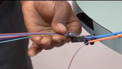
While indoor/outdoor cables are popular for eliminating the need for service entrance splicing to in-building cable, OSP loose-tube 250um cabling must be terminated within 50 feet of entering a facility. To accomplish this, breakout kits are used to build the 250um cable up for protection and termination to 900um connector boots. The problem with breakout kits is that they add additional material costs and a significant amount of labor. One option is to terminate the 250um fiber directly to 250um connector boots. This can speed network deployment in the data center and fiber-to-the-home applications.

What’s the Difference Between Twisted Pair vs Coaxial Cable vs Fiber Optic

Share

As we know, communication system usually uses a wire or cable to connect sending and receiving devices. Currently, the most common network cable types deployed in communication system are twisted pair vs coaxial cable vs fiber optic cable. Since each of them can be equally applied into network communication, what’s the difference between twisted pair vs coaxial cable vs fiber optic? This article may give some answers.

Twisted Pair Cables
Twisted Pair
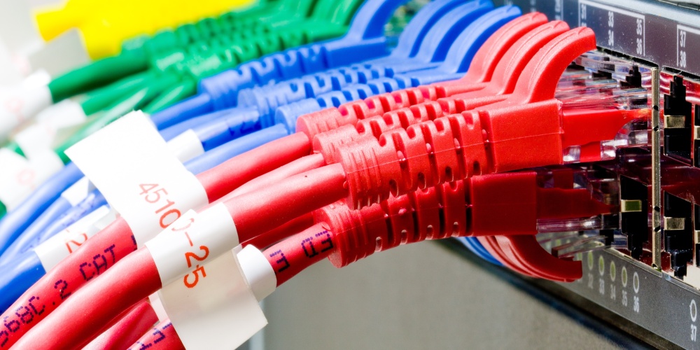
Twisted pair cable consists of a pair of insulated wires twisted together, which is adapted in the field of telecommunication for a long time. With the cable twisting together, it helps to reduce noise from outside sources and crosstalk on multi-pair cables. Basically, twisted pair cable can be divided into two types: unshielded twisted-pair (UTP) and shielded twisted-pair (STP). The former serves as the most commonly used one with merely two insulated wires twisted together. Any data communication cables and normal telephone cables belong to this category. However, shielded twisted pair distinguishes itself from UTP in that it consists of a foil jacket which helps to prevent crosstalk and noise from outside source. It is typically used to eliminate inductive and capacitive coupling, so it can be applied between equipment, racks and buildings. There exist following several different types of twisted pair cables:

Twisted Pair Cables

Coaxial Cables
Coaxial-Cable
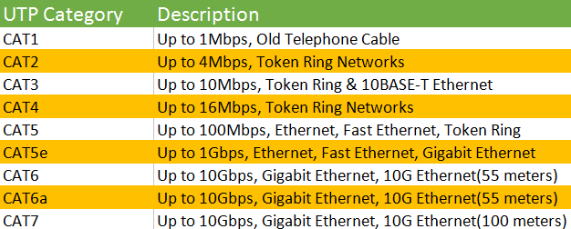
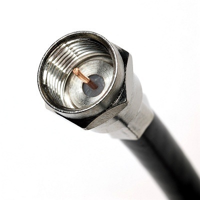
Coaxial cable acts as a high-frequency transmission cable which contains a single solid-copper core. A coaxial cable has over 80 times the transmission capability of the twisted-pair. It is commonly used to deliver television signals and to connect computers in a network as well, so people may get more familiar with this kind of network cable. There are two coaxial cables: 75 Ohm and 50 Ohm. What’s the application of them respectively?

  • 75 Ohm coaxial cable

The primary use of a 75 Ohm cable is to transmit a video signal. One of the typical applications is television signals over network cable, sometimes called signal feed cables. The most common connector used in this application is a Type F. Another application is video signals between components such as DVD players, VCRs or Receivers commonly known as audio/video (A/V) cables. In this case BNC and RCA connectors are most often found. In both of these applications RG59 with both solid center conductor (RG59B/U) and stranded center conductor (RG59A/U) as well as RG6 are often found.

75 Ohm coaxial cable

  • 50 Ohm coaxial cable

The primary use of a 50 Ohm coaxial cable is transmission of a data signal in a two-way communication system. Some common applications for 50 Ohm coaxial cable are computer ethernet backbones, wireless antenna feed cables, GPS (Global Positioning Satellite) antenna feed cables and cell phone systems.

50 Ohm coaxial cable (1)

Fiber Optic Cable

Picture of optical cables pluged in network server

Computing and data communications are fast-moving technologies. There comes a new generation of transmission media—fiber optic cable. It refers to the complete assembly of fibers, which contain one or more optical fibers that are used to transmit data. Each of the optical fiber elements is individually coated by plastic layers and contained in a protective tube. Fiber optic cable transmits data as pulses of light go through tiny tubes of glass, the transmission capacity of which is 26,000 times higher than that of twisted-pair cable. When comparing with coaxial cables, fiber optic cables are lighter and reliable for transmitting data. They transmit information using beams of light at light speed rather than pulses of electricity.

Nowadays, there are two fiber optic cable types widely adopted in the field of data transfer—single mode fiber optic cable and multimode fiber optic cable. A single-mode optical fiber is a fiber that has a small core, and only allows one mode of light to propagate at a time. So it is generally adapted to high speed, long-distance applications. While a multimode optical fiber is a type of optical fiber with a core diameter larger than the wavelength of light transmitted and it is designed to carry multiple light rays, or modes at the same time. It is mostly used for communication over short distances because of its high capacity and reliability, serving as a backbone application in buildings.

Singlemode-vs-Multimode Fiber Optic Cable

Conclusion of Twisted Pair vs Coaxial Cable vs Fiber Optic
As the technology in the field of the network is developing rapidly, network cable seems to become the trend for the increasing demand of the market. After learning the difference between twisted pair vs coaxial cable vs fiber optic, we know how to choose network cable. However, whether to choose twisted pair cables, coaxial cables or fiber optic cables still depends heavily on applications, which is subject to the cost, transmission distance and performance.

Related Article: Which Patch Cable Should I Choose for My Optical Transceiver?

Fiber Optic Cable vs Twisted Pair Cable vs Coaxial Cable

6 Steps Help to Choose Right Fiber Patch Cord Types

Share

There are many fiber patch cord types, such as OM1, OM2, OM3, OM4 multimode fiber and OS2 single mode fiber types. Both ends of the cable are terminated with a high performance hybrid or single type connector comprising of a SC, ST, FC, LC, MTRJ, E2000 connector in simplex and duplex. These are typically not ruggedized, depending on the application, making them suitable for internal use. How to choose right fiber patch cord types for your network? Just follow these 6 steps.

Step 1: Choose the Right Connector Type (LC/SC/ST/FC/MPO/MTP)

Different fiber patch cord types
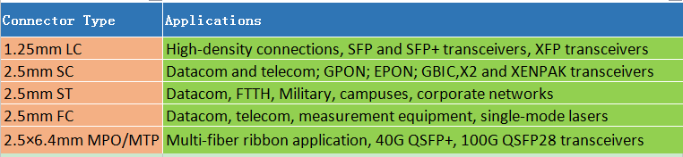
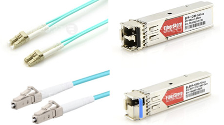
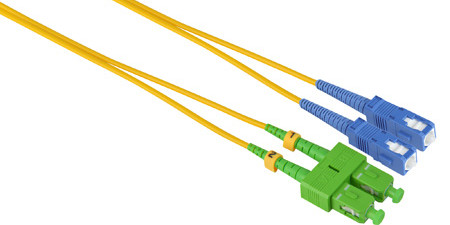
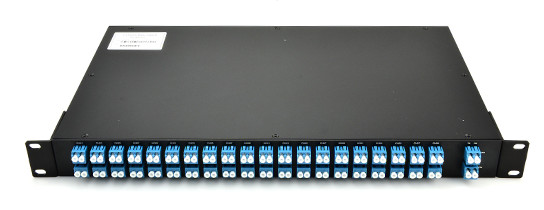
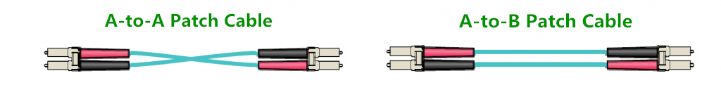
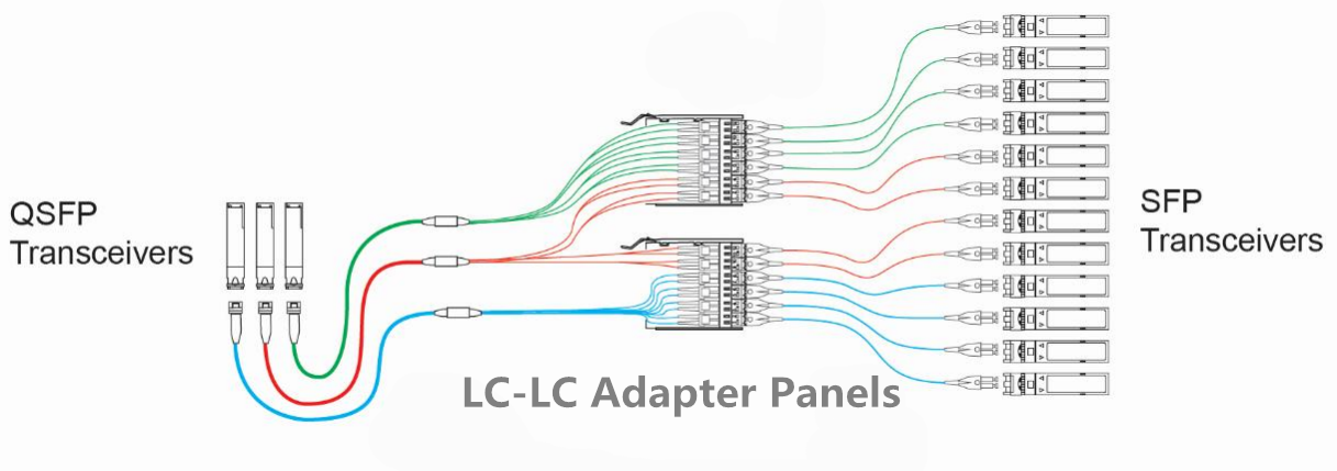
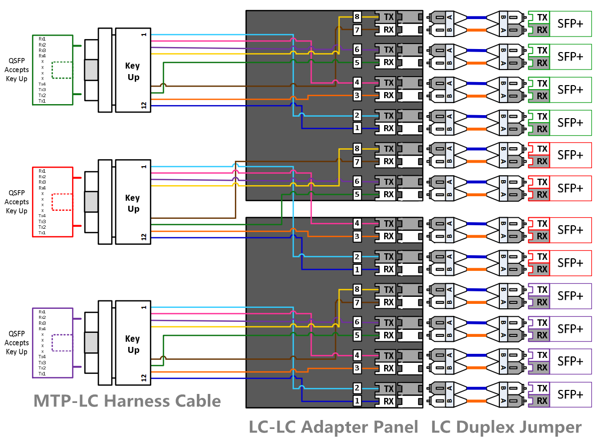
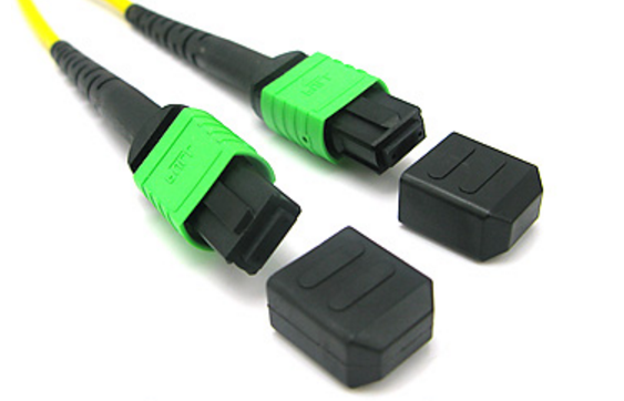
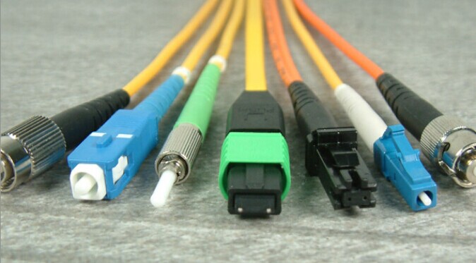
On both ends of the fiber optic patch cord are terminated with a fiber optic connector (LC/SC/ST/FC/MPO/MTP). Different connector is used to plug into different device. If ports in the both ends devices are the same, we can use such as LC-LC/SC-SC/MPO-MPO patch cables. If you want to connect different ports type devices, LC-SC/LC-ST/LC-FC patch cables may suit you.

LC SC ST FC MPO MTP fiber optic patcah cable

Step 2: Choose Single-mode or Multimode Cable Type?
Single-mode fiber patch cord uses 9/125um glass fiber, Multimode fiber patch cord uses 50/125um or 62.5/125um glass fiber. Single-mode fiber optic patch cord is used in long distance data transmission. multimode fiber optic patch cord is use in short distance transmission. Typical single-mode fiber optic patch cord used yellow fiber cable and multi mode fiber optic patch cord used orange or aqua fiber cable.

single-mode multimode fiber optic patch cable

Step 3: Fiber Patch Cord Types – Choose Simplex or Duplex?
Simplex means this fiber patch cable is with one cord, at each end is only one fiber connector, which is used for Bidirectional (BIDI) fiber optic transceivers. Duplex can be regarded as two fiber patch cable put side by side, which is used for common transceivers.

simplex duplex fiber optic patch cable

Step 4: Choose the Right Cable Length (1m/5m/10m/20m/30m/50m)
Fiber optic patch cables are made in different lengths, usually from 0.5m to 50m. You should choose an appropriate cable length according to the distance between the devices you want to connect.

Step 5: Choose the Right Connector Polish Type (UPC/APC)
Since the loss of the APC connector is lower than UPC connectors, usually, the optical performance of APC connectors is better than UPC connectors. In the current market, the APC connectors are widely used in applications such as FTTx, passive optical network (PON) and wavelength-division multiplexing (WDM) that are more sensitive to return loss. But APC connector is usually expensive than UPC connector, so you should weigh the pros and cons. With those applications that call for high precision optical fiber signaling, APC should be the first consideration, but less sensitive digital systems will perform equally well using UPC. Usually, connector color of APC patch cable is green, and of UPC patch cable is blue.

UPC APC fiber optic patch cable

Step6: Choose the Right Cable Jacket Type (PVC/LSZH/OFNP/Armored)
Usually, there are three cable jacket types: Polyvinyl Chloride (PVC), Low Smoke Zero Halogen (LSZH) and Optical Fiber Nonconductive Plenum (OFNP). You can see there features in figure below and choose the right one for your network.

PVC LSZH OFNP Fiber Optic Patch Cable
Besides the three cables mentioned above, there is another common cable—Armored Cable. The double tubing and steel sleeve construction make these patch cables completely light tight, even when bent. These cables can withstand high crushing pressures, making them suitable for running along floors and other areas where they may be stepped on. The tubing also provides excellent cutting resistance, abrasion resistance, and high tensile strength.

Armored Fiber Optic Patch Cable

FS.COM provides all kinds of fiber optic patch cables to meet demands of various customers!

Related Article:

 Common Types of Fiber Patch Cables

What Kind of Fiber Patch Cord Should I Choose?

Use Cisco DWDM SFP+ to Connect DWDM Transport to Your Cisco 10G Switches

Share

Dense Wavelength Division Multiplexing (DWDM) enables carrier’s networks to accommodate many hundreds of aggregated services of any sub-rate protocol without installing additional dark fiber. DWDM SFP+ transceiver is mainly manufactured for carriers and large enterprises that need a scalable, flexible, cost-effective system for multiplexing, transporting and protecting high-speed data, storage, voice and video applications. The Cisco DWDM SFP+ transceiver modules are fiber line cards for a wide variety of Cisco switches, routers, and other equipment. They allow enterprises and service providers to provide scalable and easy-to-deploy 10-Gbps LAN, WAN, and optical transport network (OTN) services in their networks.

Cisco DWDM SFP+ Transceiver Channels

According to DWDM ITU (ITU-T G.694.1) channels, Cisco DWDM SFP+ transceivers are provided with 40 channels, from C20 1561.41nm to C59 1530.33nm (shown in the table below).

PN. ITU Channel PN. ITU Channel PN. ITU Channel
DWDM-SFP10G-61.41 C20 1561.41 nm DWDM-SFP10G-50.12 C34 1550.12 nm DWDM-SFP10G-38.98 C48 1538.98 nm
DWDM-SFP10G-60.61 C21 1560.61 nm DWDM-SFP10G-49.32 C35 1549.32 nm DWDM-SFP10G-38.19 C49 1538.19 nm
DWDM-SFP10G-59.79 C22 1559.79 nm DWDM-SFP10G-48.51 C36 1548.51 nm DWDM-SFP10G-37.40 C50 1537.40 nm
DWDM-SFP10G-58.98 C23 1558.98 nm DWDM-SFP10G-47.72 C37 1547.72 nm DWDM-SFP10G-36.61 C51 1536.61 nm
DWDM-SFP10G-58.17 C24 1558.17 nm DWDM-SFP10G-46.92 C38 1546.92 nm DWDM-SFP10G-35.82 C52 1535.82 nm
DWDM-SFP10G-57.36 C25 1557.36 nm DWDM-SFP10G-46.12 C391546.12 nm DWDM-SFP10G-35.04 C53 1535.04 nm
DWDM-SFP10G-56.55 C26 1556.55 nm DWDM-SFP10G-45.32 C40 1545.32 nm DWDM-SFP10G-34.25 C54 1534.25 nm
DWDM-SFP10G-55.75 C27 1555.75 nm DWDM-SFP10G-44.53 C41 1544.53 nm DWDM-SFP10G-33.47 C55 1533.47 nm
DWDM-SFP10G-54.94 C28 1554.94 nm DWDM-SFP10G-43.73 C42 1543.73 nm DWDM-SFP10G-32.68 C56 1532.68 nm
DWDM-SFP10G-54.13 C29 1554.13 nm DWDM-SFP10G-42.94 C43 1542.94 nm DWDM-SFP10G-31.90 C57 1531.90 nm
DWDM-SFP10G-53.33 C30 1553.33 nm DWDM-SFP10G-42.14 C44 1542.14 nm DWDM-SFP10G-31.12 C58 1531.12 nm
DWDM-SFP10G-52.52 C31 1552.52 nm DWDM-SFP10G-41.35 C45 1541.35 nm DWDM-SFP10G-30.33 C59 1530.33 nm
DWDM-SFP10G-51.72 C32 1551.72 nm DWDM-SFP10G-40.56 C46 1540.56 nm
DWDM-SFP10G-50.92 C33 1550.92 nm DWDM-SFP10G-39.77 C47 1539.77nm

Cisco Switches Support for Cisco DWDM SFP+

In fact, not all Cisco switches can be supported for DWDM SFP+ transceivers. According to Cisco 10-Gigabit Ethernet Transceiver Modules Compatibility Matrix, there are 72 types of Cisco switches are available to support DWDM SFP+ transceivers. But only 19 of them can support be supported all 40 channels DWDM SFP+ transceivers (shown in the table below).

Switches Series Models
Cisco Nexus 3000 Series N3K-C3016Q-40GE, N3K-C3064PQ-10GE, N3K-C3064TQ-10GT, N3K-C3064PQ-10GX
Cisco Nexus 3100 Series N3K-C3132Q-40GE, N3K-C3132Q-40GX, N3K-C3132Q-XL, N3K-C3132Q-V, N3K-C3172PQ-10GE, N3K-C3172TQ-10GT, N3K-C3172PQ-XL, N3K-C3172PQ-XL, N3K-C3172TQ-XL, N3K-C31108PC-V, N3K-C31108PC-V
N3K-C31108TC-V, N3K-C31128PQ-10GE
Cisco Nexus 3200 Series N3K-C3264Q, N3K-C3232C
Cisco Nexus 3500 Series N3K-C3548P-10G , N3K-C3524P-10G, N3K-C3548P-10GX, N3K-C3524P-10GX

To build a complete DWDM network in your system, except for switches and DWDM SFP+ transceivers, you also usually need a DWDM mux/demux module. At present, DWDM mux/demux modules are available in 2 channels to 96 channels. Since Cisco DWDM SFP+ transceivers are available in 40 channels (from C20 1561.41nm to C59 1530.33nm ), now I will take 40 channels C20-C59 DWDM mux/demux module (show in the figure below) for example to explain how it works.

40 channels DWDM mux demux

Front panel of above 40 channels C20-C59 DWDM mux/demux module are shown in the figure below. Connectors, located on the front of the DWDM mux/demux modules, are labeled and use the same channel that is used to indicate the wavelength of the individual DWDM transceivers.

DWDM muxdemux
Use a pair of 40 channels C20-C59 DWDM mux/demux modules, 40 signals can be transmitted over one fiber pair, which greatly reduces the cabling cost.

40 DWDM muxdemux
Now, let’s use Cisco compatible DWDM SFP+ to connect DWDM transport to your Cisco 10G SFP+ switches!

Cisco Compatible DWDM SFP+

CWDM Mux/Demux User Guide

Share

When we demand for higher bandwidth, we often choose to install new fiber. However, that is an expensive solution. Then what should we do? Now this article will give you a less expensive solution—using CWDM Mux/Demux with CWDM transceivers, which may allow you to maximize capacity and increase bandwidth on existing fiber route by multiplexing several distinct signals or protocols over a single or duplex-fiber connection. The passive optical CWDM Mux/Demux usually utilizes a thin-film filter and circulator technology. They are available in various wavelength combinations based on the entire wavelength spectrum (1270nm–1610nm in 20nm increments) defined by the ITU G.694.2 CWDM standard. Accordingly, CWDM transceivers are also available in 1270nm–1610nm (20nm spacing).

Since CWDM Mux/Demux can support 18 wavelengths include 1270, 1290, 1310, 1330, 1350, 1370, 1390, 1410, 1430, 1450, 1470, 1490, 1510, 1530, 1550, 1570, 1590 and 1610 nano-meters. Therefore, in the market, the channels of CWDM Mux/Demux varies from 2 channels to 18 channels. In this article, we may introduce these 4 channels CWDM Mux/Demux in detail. Using methods of other channel CWDM Mux/Demux can all reference 4 channels CWDM Mux/Demux.4 channels CWDM Mux/Demux is available in any four wavelengths from 1270nm–1610nm (20nm spacing). At present, CWDM Mux/Demux is available in dual fiber and single fiber two types. In the following passages, I will take 4 channels 1510-1570nm dual fiber CWDM Mux/Demux and 4 channels 1470-1590nm single fiber CWDM Mux/Demux for example to tell you how to use them in your WDM network.

4 Channels 1510-1570nm Dual Fiber CWDM Mux/Demux User Guide
To install a  4 channels 1510-1570nm dual fiber CWDM Mux/Demux in your network, you need a pairs of  4 channels 1510-1570nm dual fiber CWDM Mux/Demux. For dual fiber link  CWDM Mux/Demux, the Mux/Demux are always the same (shown in the following picture).

CWDM Mux/Demux User Guide

Just shown as the following picture. To install a  4 channels 1510-1570nm dual fiber CWDM Mux/Demux in your network, you just need a pair of 4 channels 1510-1570nm dual fiber CWDM Mux/Demux, a 1510nm SFP, 1530nm SFP1550nm SFP and a 1570nm SFP.

4 Channels 1510-1570nm Dual Fiber CWDM MuxDemux

4 Channels 1470-1590nm Single Fiber CWDM Mux/Demux User Guide
To install a  4 channels 1470-1590nm single fiber CWDM Mux/Demux in your network, you also need a pairs of  4 channels single fiber CWDM Mux/Demux. But for single fiber Mux/Demux, they are not the same. If you install a  4 channels 1470-1590nm single fiber CWDM Mux/Demux on one end, you may need to install a 4 channels 1490-1610nm single fiber CWDM Mux/Demux on the other end (shown in the following picture).

CWDM Mux/Demux User Guide

Just shown as the following picture. To install a  4 channels 1470-1590nm single fiber CWDM Mux/Demux in your network, you need a 4 channels 1470-1590nm single fiber CWDM Mux/Demux and 4 channels 1490-1610nm single fiber CWDM Mux/Demux pair. And a 1470nm SFP, 1510nm SFP, 1550nm SFP and 1590nm SFP for 4 channels 1470-1590nm single fiber CWDM Mux/Demux. A 1490nm SFP, 1530nm SFP, 1570nm SFP, 1610nm SFP for  4 channels 1490-1610nm single fiber CWDM Mux/Demux.

Single-Fiber CWDM Mux Demux Application

How to Ensure MTP/MPO Polarity of the Patch Cable Is Always Right?

Share

As we know, in order to ensure the right MTP/MPO polarity, transmit signal (Tx) at one end of the cable must match the corresponding receiver (Rx) at the other end of the cable. In some complex cabling deployment, it seems not much simple. Now this article may give you some golden rules to help you ensure the right MTP/MPO polarity of Patch Cables.

You’d Better Use the Same Type Patch Cable
When fiber optic patch cables have different polarity (for example, MTP or MPO polarity), we must to be very careful when replacing patch cables in our network. If you don’t understand polarity and use the wrong polarity patch cables, it may influence the transmission the damage your device. To decrease this risk, we recommend that you’d better use the same patch cables in your network.

Type A/B LC Duplex and Type B Female-to-Female MPO Patch Cables Are Common
Two types of duplex fiber patch cord are defined in the TIA standard: A-to-A (cross-over) type and A-to-B (straight-through) type. Note: A-to-A patch cords are not commonly deployed and should be used only when necessary as part of a polarity method (See ANSI/TIA-568-C.0).

Type A/B LC Duplex cable

The three methods for proper polarity defined by TIA 568 standard are named as Method A, Method B and Method C. To match these standards, three type of MPO trunk cables with different structures named Type A, Type B and Type C are being used for the three different connectivity methods respectively. As shown in the figure below, type A MPO cables just like the A-to-A duplex cables, Tx can’t match the Rx. Type C MPO cables use a pair flip design, which aren’t suitable for 40GBASE-SR4 and 100GBASE-SR4 standard. Therefore, we should use Type B MPO cables for connection.

MPO_to_MPO_Polarity
For MTP/MPO cables, gender is a big problem. MTP/MPO interfaces on optical transceivers are always male (pinned). To avoid damage to the optical module, MTP/MPO polarity must always be female-to-female (unpinned). Besides, there is a rule must be obeyed if we want to connect an MPO patch cable to another cable. That is a male patch cable must be connected to a female patch cable. Never connect a male to a male one or a female to a female one.

MPO patch cable male female polarity

Three Connection Methods Help Keep the Right MTP/MPO Polarity
1. Type A connection
One end of Type A MPO/MTP patch cord is A-B normal patch cord, the other end A-A. Between MPO/MTP patch cord and normal patch cord is Type A MPO/MTP cassette and Type A MPO/MTP adapter (The two keys of type A adapter is opposite levels)

Type A connection

2. Type B connection
Both ends of Type B MPO/MTP patch cord are A-B normal patch cord. Between MPO/MTP patch cord and normal patch cord is Type B MPO/MTP cassette and Type B MPO/MTP adapter (The two keys of type B adapter is same level)

Type B connection

3. Type C connection
Both ends of Type C MPO/MTP patch cord are A-B normal patch cord. Between MPO/MTP patch cord and normal patch cord is Type A MPO/MTP cassette and Type A MPO/MTP adapter (The two keys of type A adapter is opposite levels)

Type C connection

All kinds of duplex patch cables and MPO patch cables are available and in stock for same-day shipping in FS.COM. For more information, you can contact us at sales@fs.com.

Related Article:

Unveil Polarity of MTP/MPO Multi-Fiber Cable Solutions

Polarity and MPO Technology in 40/100GbE Transmission

25G SFP28 Cable: The Most Economical Option for ToR Server Connection

Share

Have you ever heard of 25G SFP28 cable? It is said to be regarded as the most economical option for ToR server connection. Continue to read and get more details.

What’s 25G SFP28 Cable?

As you may know that 25 Gigabit Ethernet is proposed standard for Ethernet connectivity in a data center environment, developed by IEEE 802.3 task force P802.3by. The IEEE 802.3bj standard then uses technology defined for 100 Gigabit Ethernet implemented as four 25-Gbit/s lanes. These standards define:

  • a single-lane 25 Gbit/s 25GBASE-KR PHY for printed circuit backplanes
  • a single-lane 25 Gbit/s 25GBASE-CR-S PHY for 3 m twin-ax cables (in-rack)
  • a single-lane 25 Gbit/s 25GBASE-CR-L PHY for 5 m twin-ax cables (inter-rack)
  • a single-lane 25 Gbit/s 25GBASE-SR PHY for 100 m OM4 or 70 m OM3 multi-mode optical fiber

According to the above standards, the IEEE CFI is now focused on the SFP28 and QSFP28 direct attach copper twin-ax cables (DACs). SFP28 DAC refers to the 25G DAC cable using the SFP+ form factor, and QSFP28 DAC refers to the 100G DAC cable using the QSFP+ form factor. The maximum transmission distance of these cables is 5 meters.

There are two SFP28 cable types: 25G SFP28 to SFP28 DAC and 100G QSFP28 to four SFP28 breakout DAC. The SFP28 to SFP28 passive copper cable is a high speed, cost-effective 25Gbp/s Ethernet connectivity solution designed to meet the growing needs for higher bandwidth in data centers. The QSFP28 to four SFP28 breakout DAC is used to connect 100G switches to four 25 Gigabit in cabinet or adjacent cabinet servers. Compared to 40G using four 10G lanes and 100G using 10 10G lanes, the 25G SFP28 DAC provides the low-cost copper server connection for Top of Rack (ToR) switches.

To more directly illustrate effectiveness of SFP28 to SFP28 DAC cable and QSFP28 to four SFP28 breakout DAC cable, let’s see a series of pictures displayed below:

Existing 10G Topology
Today’s volume topology for web-scale data centers

  • 48 servers/ToR
  • 3:1 oversubscription
  • Uses low-cost, thin 4-wire SFP+ DAC cable

sfp+ to sfp+ DAC

40G Topology
High-performance, low volume topology

  • Uses bulkier 16-wire QSFP+ DAC cable
  • Max. 24 servers/ToR with 3:1 oversubscription
  • Will transition to 100G

qsfp+ to qsfp+ dac

25G Direct Connect
Same topology as 10G

  • 48 servers/ToR
  • 3:1 oversubscription w/ 100G uplinks, non-blocking w/ 400G
  • Uses 4-wire SFP28 DAC cable

sfp28 to sfp28 dac

Existing 4x10G Topology
Commonly used topology in web-scale data centers

  • Permits non-blocking 10G mesh
  • 40G ports used as 4x10G with QSFP+ to SFP+ breakout cable
  • Same server network interface card (NIC) as 10G

qsfp+ to 4 sfp+ dac

4x25G Breakout
Same topology as 4x10G

  • Permits non-blocking 25G mesh
  • 100G ports used as 4x25G with QSFP28 to SFP28 break-out cable
  • Same server network interface card (NIC) as 25G direct connect

qsfp28 to 4 sfp28 dac

High Density 25G
Increased port switch port density

  • 64 servers in non-blocking architecture
  • 96 servers in a 3:1 oversubscription
  • 24-port 400G ToR
  • 192 servers in non-blocking architecture

100G qsfp28 to 4 sfp28 dac

Related articles:

Taking an In-depth Look at 25G SFP28

25G Vs. 40G Ethernet: Who Is the Winner?

How Far Can 25G Ethernet Go?

The Changing Network Architecture in 25G/100G Data Center

10G SFP+ and 40G QSFP+ Transceivers Cabling Solutions

Share

This article will discuss different connection methods between parallel Quad Small Form-factor Pluggable (QSFP+) transceivers and Small Form-factor Pluggable (SFP+) transceivers. As we know, a 40G QSFP+ transceiver can be either an 8-fiber parallel link or a 2-fiber duplex link. In this document when QSFP is used we will be discussing an 8-fiber parallel link. A SFP+ transceiver is usually an 2-fiber duplex link. According to standard, since QSFP+ is 40G interface, SFP+ is 10G interface, therefore four SFP+ transceiver must be needed to connect to one QSFP+ transceivers to achieve 40G transmission.

40G QSFP+ to 10 SFP+ Direct Connectivity Solutions
When directly connecting a QSFP port to the four corresponding SFP ports, an eight fiber MTP-LC breakout cable is required. The harness will have four LC Duplex connectors and the fibers will be paired in a specific way, assuring the proper polarity is maintained. This type of direct connectivity is only suggested for short distances within a given row or in the same rack/cabinet.

10G SFP+ and 40G QSFP+ direct connection

  • Polarity Drawing for Above Scenario 

Polarity Drawing for Direct Connectivity Solutions

40G QSFP+ to 10 SFP+ Interconnect Solutions
The 40G QSFP+ to 10 SFP+ interconnect solution shown in figure below shows one link with a breakout of the QSFP with the use of an MTP-LC module to four SFP links. A Type-B non-pinned MTP to non-pinned MTP cable is used between MTP-LC modulethe MTP-LC module and QSFP transceiver. The connection to the SFP transceivers is accomplished with Uniboot LC duplexed jumpers. This is a solution that is only recommended for short distances, where the patching takes place within a given row of racks/cabinets. This solution does present some disadvantages which are that ports 5 & 6 of the module are not being used thus reducing the patch panel density. It may also create some confusion when patching occurs since these two ports are dark.

SFP+ QSFP+ Interconnect Solutions

  • Polarity Drawing for Above Scenario Polarity Drawing for 10G SFP+ and 40G QSFP+ Interconnect Solutions

Unlike the patching approach in figure above, the solution shown in figure below has no dark fibers oLC-LC adapter panelr ports. The Type-B jumper is replaced with an eight-fiber harness. The modules are replaced with the LC-LC adapter panel. Using this approach allows full patch panel density that was lost in the previous example. Only two LC-LC adapter panels will be required for every three 8-fiber harnesses. All ports on the LC-LC adapter panels will be used and the connections to the 10GbE ports will be completed with an Uniboot LC duplexed jumper. This solution should also be deployed when there is a short distance between active components (within the same row). Note the LC panel does not support the LC Uniboot connector, only LC Duplex connectors with the triggers removed to avoid clearance issues with the panel cover.

10G 40G Interconnect Solutions

  • Polarity Drawing for Above Scenario 

Polarity Drawing for 10G SFP+ and 40G QSFP+ Solution

Fiberstore (FS.COM) provide all the products mentioned above, including 10G SFP+ transceivers, 40G QSFP+ transceivers, MTP patch cables, MTP-LC harness cable, MTP-LC module and LC-LC adapter panel. All in stock and can be shipped the same day.

Related article: It’s Time to Use MTP Cassettes in Your Network!

Why Demand for Ultra High Density Fiber Optic Enclosures?

Share

Increased demand for data to support streaming media and the increased use of mobile broadband communications has resulted in dramatic advances in network switching infrastructure over the past 10 years. Furthermore, this demand is expected to continue at a record pace. Since the transition from copper to fiber as the standard for high-performance data communications and the number of fibers used to support emerging standards, such as 100GBit/s Ethernet, for the individual connection has increased, to choose higher density fiber optic enclosures is certainly innate.

Currently, network switching products are available with port line cards that use more than 1,000 OM3 fiber and OM4 fibers per chassis switch for 10G duplex fiber applications. Future 40/100Gb switches are projected to use more than 4,000 fibers per chassis where parallel optics is used. These high fiber count requirements demand high-density cable and hardware solutions that will reduce the overall footprint and simplify cable management and connections to the electronics.

Fiberstore’s new FMT1-4FAP-LCDX series product allows customers to migrate from a standard 2U fiber enclosure that will house 3 adapter panels for a maximum of 72 LC connectors to our new 96 ports fiber optic enclosures that will hold 4 adapter panels in a 1U space allowing a maximum of 96 LC connectors! This gives users 33% (or 24 more) more LC connections in a 1U enclosure versus a 2U enclosure.

96 Ports Fiber Optic Enclosure

Besides, you can get more density by utilizing our MPO/MTP to LC cassette module. Our HDSM-12MTP/MPO rack mountable MTP cassette is loaded with 72 LC duplex connectors, giving it 144 ports total within 1U of rack space. And this 1U enclosures can be mounted vertically so you can match every blade in the switch to each enclosure. This high-density MTP cassette is constructed of light weight, yet durable, rolled steel. The shallow depth of the Ultra Panel makes it suitable for copper racking systems or telecommunication rack infrastructure.

144 Ports Fiber Optic Enclosure

With the rise in demand for higher bandwidth and faster download speeds, FS.COM high-density fiber optic enclosures were designed to keep pace with these requirements. In addition, both of these unique fiber optic enclosure lines offer installers easy terminations, and performance-driven connectivity. Couple that with FS.COM’s proven fiber optic cable, in particular, our HD push-pull tab patch cables, customers can expect an exceptional solution to fit their high-density needs.

Why Do You Need MTP Pre-Terminated Fiber Solutions?

Share

Today’s modern data center proposition continues to promote the hot topics around consolidation, reduced operating expense, flexibility, scalability and of course being as ‘Green’ as possible along the way. That sounds simple, but when you start to achieve all of the above, maybe difficult than you imagine. Recently, more and more mission critical enterprise networks are considering the need for multiple fibers in a high density, modular and pre-terminated solution. Why are they become so popular? And do you also consider this solution for your network?

Some Changes Occurred in Panel to Panel Links
We have seen panel to panel links, both copper and fiber being installed for many years. These tend to be mainly in data centres, linking up racks, and therefore providing easy moves and changes within local patching fields. But, the trouble is these fibers are terminated and then fixed permanently in to place. In the past, a fiber installation would have involved a good amount of forward thinking, ensuring that the planned lengths were precise as there would be little movement to rectify any mistakes. This would result in a costly installation. Therefore, it’s clear that high speed enterprise networks are already demanding and installing multiple fibers MTP solution, meaning selecting that right easy and expandable fiber infrastructure choice from the offset is of vital importance.

Pre-Terminated MTP Connection Becomes the Hottest Topic
When it comes down to fiber it has to be the pre-terminated MTP connections, providing new advancing technologies that provide multiple fibers in a very small and modular footprint. MTP type connectors, also referred to as MPO, supplying you with a single trunk cable of either 12 or 24 cores. All in all, not much thicker than a standard fiber patch lead, so greatly reduced in size from previous pre-terminated fiber cable installations. However, already being requested are larger cores of 36, 48, 72, 96 or even 144 – but do keep in mind that these will be thicker in construction and could be made of multiple cores on a number of separate cables.

12 24 MTP MPO connector

Where Could Pre-Terminated MTP Solution Be Used?
The MTP to MTP fiber cassettes suit various environments, applications and budgets. Primarily, data centres, DR-Co locations, FCoE SAN’s, links between floors/risers and larger communication rooms. Basically, for anyone that needs to quickly create a 10 Gigabit performance fiber network backbone. All of these demand, and would ultimately benefit, from the uncompromised performance, density and scalability that MTP solutions can provide. Additional to the MTP to MTP cassette links, we are also seeing an increased demand for ‘last metre’ fan out cables. For example, 12x LC connections to a single MTP adapter, being used for direct 40 Gigabit equipment links. With the ever increasing need for more bandwidth and virtualisation of application 40Gbp’s speeds are already being installed in data centers.

MTP Pre-Terminated Fiber Solution

How Does It All Stack Up?
Supplied as part of the MTP solution is a 1U rack mountable fiber enclosure, so the installation is extremely easy. Each 1U enclosure will hold 3 cassettes and at the back of each cassette you can then access the MTP trunk cable male socket(s). The more cassettes you purchase the more 1U trays are supplied. You will then find at the front of multimode or single-mode cassettes are the legacy LC fiber connections, in either a 6 or 12 duplex (12 or 24 Core), to link back to the active network hardware or existing patch panels. Minimal time is required for the installation, with no need for onsite fiber termination and better still no out of hours working, allowing you to experience the highest performance from your network.

MTP cassette

If you would like any further information around our easy and expandable MTP fiber solution then please do get in touch with us at sales@fs.com or visit our website at www.fs.com. Thanks for reading and I hope this article has been a useful introduction to MTP pre-terminated fiber solution.