

This article will discuss different connection methods between parallel Quad Small Form-factor Pluggable (QSFP+) transceivers and Small Form-factor Pluggable (SFP+) transceivers. As we know, a 40G QSFP+ transceiver can be either an 8-fiber parallel link or a 2-fiber duplex link. In this document when QSFP is used we will be discussing an 8-fiber parallel link. A SFP+ transceiver is usually an 2-fiber duplex link. According to standard, since QSFP+ is 40G interface, SFP+ is 10G interface, therefore four SFP+ transceiver must be needed to connect to one QSFP+ transceivers to achieve 40G transmission.
40G QSFP+ to 10 SFP+ Direct Connectivity Solutions
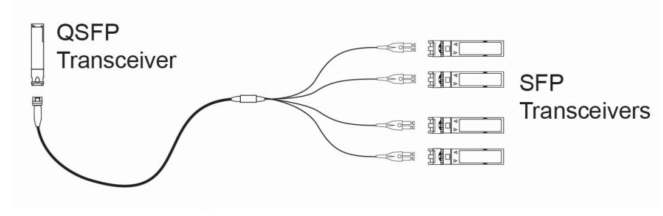
When directly connecting a QSFP port to the four corresponding SFP ports, an eight fiber MTP-LC breakout cable is required. The harness will have four LC Duplex connectors and the fibers will be paired in a specific way, assuring the proper polarity is maintained. This type of direct connectivity is only suggested for short distances within a given row or in the same rack/cabinet.
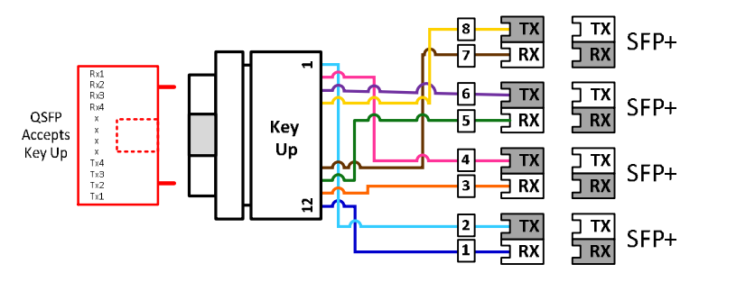
- Polarity Drawing for Above Scenario
40G QSFP+ to 10 SFP+ Interconnect Solutions
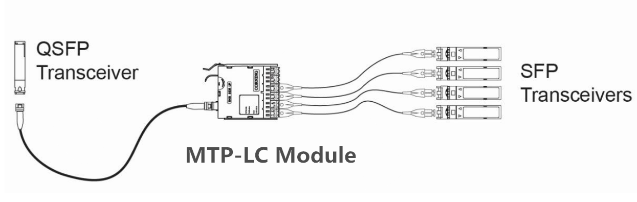
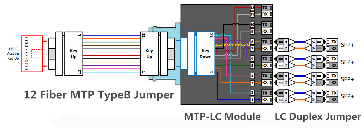
The 40G QSFP+ to 10 SFP+ interconnect solution shown in figure below shows one link with a breakout of the QSFP with the use of an MTP-LC module to four SFP links. A Type-B non-pinned MTP to non-pinned MTP cable is used between  the MTP-LC module and QSFP transceiver. The connection to the SFP transceivers is accomplished with Uniboot LC duplexed jumpers. This is a solution that is only recommended for short distances, where the patching takes place within a given row of racks/cabinets. This solution does present some disadvantages which are that ports 5 & 6 of the module are not being used thus reducing the patch panel density. It may also create some confusion when patching occurs since these two ports are dark.
- Polarity Drawing for Above Scenario
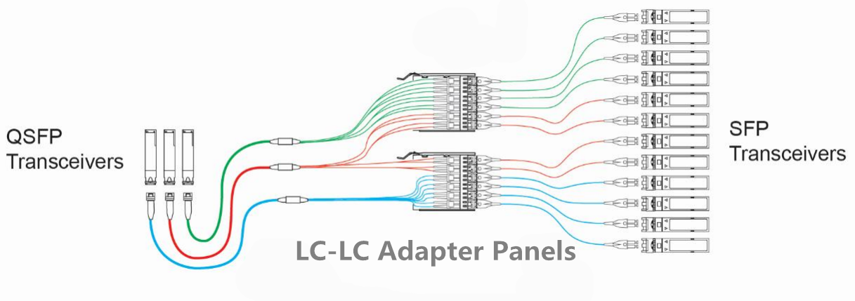
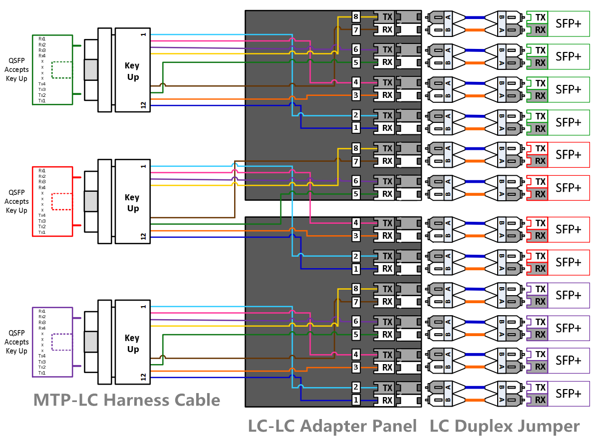
Unlike the patching approach in figure above, the solution shown in figure below has no dark fibers o r ports. The Type-B jumper is replaced with an eight-fiber harness. The modules are replaced with the LC-LC adapter panel. Using this approach allows full patch panel density that was lost in the previous example. Only two LC-LC adapter panels will be required for every three 8-fiber harnesses. All ports on the LC-LC adapter panels will be used and the connections to the 10GbE ports will be completed with an Uniboot LC duplexed jumper. This solution should also be deployed when there is a short distance between active components (within the same row). Note the LC panel does not support the LC Uniboot connector, only LC Duplex connectors with the triggers removed to avoid clearance issues with the panel cover.
- Polarity Drawing for Above Scenario
Fiberstore (FS.COM) provide all the products mentioned above, including 10G SFP+ transceivers, 40G QSFP+ transceivers, MTP patch cables, MTP-LC harness cable, MTP-LC module and LC-LC adapter panel. All in stock and can be shipped the same day.
Related article: It’s Time to Use MTP Cassettes in Your Network!