Tag Archives: 100G

Cabling Solution for Upgrading to 40G and 100G Fiber

Share

Migrating from 10G (that uses two fibers in either a SC Duplex or a LC Duplex connector) to 40G and 100G fiber will require a lot more fibers and a different type of connector. The way that optical fiber cabling is deployed for 10G can facilitate an easier migration path to 40G and 100G fiber in the future. An effective migration strategy needs to provide a smooth transition to the higher Ethernet speeds with minimum disruption and without wholesale replacement of existing cabling and connectivity components.

10G use LC duplex cabling

Optical fiber cabling is commonly deployed for backbone cabling in data centers for switch to switch connections and also for horizontal cabling for switch to server and storage area network connections. The use of pre-terminated optical fiber cabling can facilitate the migration path to 40G and 100G fiber in the future. Figure below illustrates a pre-terminated cable assembly (MPO cassette) containing 24 OS2 single-mode fibers with two 12-fiber MPO connectors at both ends. This fiber cable assembly plugs into the back of a breakout cassette that splits the 24 fibers into 12 LC Duplex connectors at the front of the cassette.

MPO cassette has duplex lc connector and MTP connector

Four of these cassettes are mounted in a one rack unit (1U) patch panel to provide up to forty-eight 10G equipment connections using LC Duplex patch cords. The FS.COM FHD 1U fiber enclosure with four LC Duplex cassettes is illustrated in Figure below.

1U fiber enclosure with four LC Duplex cassettes

If upgrading from 10G to 40G, one or more of the LC duplex cassette(s) can be replaced with 12 port MPO adapters. The MPO adapters are designed to fit in the same opening as the cassettes. The Figure below illustrates the case where all four cassettes are replaced with four high density 12 port MPO adapters. This solution illustrates an upgrade path from 10G to 40G that does not require any additional space and reuses the same patch panels. The 12 LC duplex cassette(s) are replaced with 12 port MPO adapter(s) as needed. Additional 24-fiber cable assemblies (or any fiber counts in multiples of 12 fibers) are provided as needed for backbone or horizontal cabling.

1U fiber enclosure with four MPO adapter

25G SFP28 Cable: The Most Economical Option for ToR Server Connection

Share

Have you ever heard of 25G SFP28 cable? It is said to be regarded as the most economical option for ToR server connection. Continue to read and get more details.

What’s 25G SFP28 Cable?

As you may know that 25 Gigabit Ethernet is proposed standard for Ethernet connectivity in a data center environment, developed by IEEE 802.3 task force P802.3by. The IEEE 802.3bj standard then uses technology defined for 100 Gigabit Ethernet implemented as four 25-Gbit/s lanes. These standards define:

  • a single-lane 25 Gbit/s 25GBASE-KR PHY for printed circuit backplanes
  • a single-lane 25 Gbit/s 25GBASE-CR-S PHY for 3 m twin-ax cables (in-rack)
  • a single-lane 25 Gbit/s 25GBASE-CR-L PHY for 5 m twin-ax cables (inter-rack)
  • a single-lane 25 Gbit/s 25GBASE-SR PHY for 100 m OM4 or 70 m OM3 multi-mode optical fiber

According to the above standards, the IEEE CFI is now focused on the SFP28 and QSFP28 direct attach copper twin-ax cables (DACs). SFP28 DAC refers to the 25G DAC cable using the SFP+ form factor, and QSFP28 DAC refers to the 100G DAC cable using the QSFP+ form factor. The maximum transmission distance of these cables is 5 meters.

There are two SFP28 cable types: 25G SFP28 to SFP28 DAC and 100G QSFP28 to four SFP28 breakout DAC. The SFP28 to SFP28 passive copper cable is a high speed, cost-effective 25Gbp/s Ethernet connectivity solution designed to meet the growing needs for higher bandwidth in data centers. The QSFP28 to four SFP28 breakout DAC is used to connect 100G switches to four 25 Gigabit in cabinet or adjacent cabinet servers. Compared to 40G using four 10G lanes and 100G using 10 10G lanes, the 25G SFP28 DAC provides the low-cost copper server connection for Top of Rack (ToR) switches.

To more directly illustrate effectiveness of SFP28 to SFP28 DAC cable and QSFP28 to four SFP28 breakout DAC cable, let’s see a series of pictures displayed below:

Existing 10G Topology
Today’s volume topology for web-scale data centers

  • 48 servers/ToR
  • 3:1 oversubscription
  • Uses low-cost, thin 4-wire SFP+ DAC cable

sfp+ to sfp+ DAC

40G Topology
High-performance, low volume topology

  • Uses bulkier 16-wire QSFP+ DAC cable
  • Max. 24 servers/ToR with 3:1 oversubscription
  • Will transition to 100G

qsfp+ to qsfp+ dac

25G Direct Connect
Same topology as 10G

  • 48 servers/ToR
  • 3:1 oversubscription w/ 100G uplinks, non-blocking w/ 400G
  • Uses 4-wire SFP28 DAC cable

sfp28 to sfp28 dac

Existing 4x10G Topology
Commonly used topology in web-scale data centers

  • Permits non-blocking 10G mesh
  • 40G ports used as 4x10G with QSFP+ to SFP+ breakout cable
  • Same server network interface card (NIC) as 10G

qsfp+ to 4 sfp+ dac

4x25G Breakout
Same topology as 4x10G

  • Permits non-blocking 25G mesh
  • 100G ports used as 4x25G with QSFP28 to SFP28 break-out cable
  • Same server network interface card (NIC) as 25G direct connect

qsfp28 to 4 sfp28 dac

High Density 25G
Increased port switch port density

  • 64 servers in non-blocking architecture
  • 96 servers in a 3:1 oversubscription
  • 24-port 400G ToR
  • 192 servers in non-blocking architecture

100G qsfp28 to 4 sfp28 dac

Related articles:

Taking an In-depth Look at 25G SFP28

25G Vs. 40G Ethernet: Who Is the Winner?

How Far Can 25G Ethernet Go?

The Changing Network Architecture in 25G/100G Data Center

100G Optical Transceivers Will Be More Popular in 2016

Share

According to a newly published report by Dell’Oro Group, the worldwide service provider core router market is expected to reach $3.4 billion in revenue in 2020 as 100G port shipments spur growth. There is a significant increase in deployments of 100G ports, driven by the continuous increase in IP traffic as well as the availability of higher capacity line cards in 2015. Besides, pricing declined significantly in 2015 for 100G as there was a mix shift in the types of routers on which 100G ports were installed. Furthermore, the availability of advanced optics in CFP2 and CPAK has pushed down pricing on 100G. Therefore, we expect 100G optical transceivers will be more and more popular in 2016.

100G Optical Transceiver Modules: from CFP to QSFP28
At present market, the 100G optical transceiver module include CXP, CFP, CFP2, CPAK, CFP4 and QSFP28. Among them, QSFP28 demonstrates its great superiority and will lead to denser optics and further price reductions. The QSFP28 increases front-panel density by 250% over QSFP+. The increase in panel density is even more dramatic when compared to some of the other 100G transceiver module: 450% versus the CFP2 and 360% versus the CPAK. In addition, the surge of QSFP28 shipments will be one of the factors to change the market from 40G to 100G, according to the report of IHS. QSFP28 is fast becoming the universal data center form factor.

100G Optical Transceiver Module

100G Optical Transceiver Module Is Much Cheaper Than Before
The cost for transceiver modules which keep adding up over time is one of the main considerations of the whole projects. In other word, the cost of the devices and components may influence the enthusiasm of network upgrade. But, in 2016, the 100G transceivers will be more affordable. On one hand, the cheap 100G silicon reaches production and the technology become mature. On the other hand, the adoption of widespread use of the 100G devices, and the vast increases in Internet traffic are core to change in the communications infrastructure markets. This reduction in pricing will lead to 100 GE selling at a price per bit transmitted below that of 10 GE in the 2018 time frame.

100G Optical Transceiver Module Is More Widely Used
Previously, 100G was primarily installed on high-end core routers and now more are being installed on relatively lower-priced edge routers, which pricing declined significantly reduces the price of 100G optical transceiver. In 2016, the global data center construction market will keep growing which means that the 100G optics application will be more wider. Geographically, North America, Europe and Asia-Pacific (mainly China) are the main market for 100G transceiver with their increasing demand for deployment of 100G equipment.

Fiberstore 100G Optical transceiver Solution
In 2015, FS.COM constantly improves the product line of fiber optic transceivers. For 100G optics, we introduced the 100GBASE-LR4 CFP2 and CFP4 modules as well as the 100GBASE-SR4 and 100GBASE-LR4 QSFP28 modules. With our serious cost control, the prices of all our 100G optics are much more affordable than the similar products in the market. Furthermore, with the mature coding technology, they can be compatible with many major brands.

FS Part Number Product Photo Description
CFP-LR4-100G CFP-LR4-100G 100GBASE-LR4 CFP 1310nm 10km Transceiver for SMF
CFP2-LR4-100G CFP2-LR4-100G 100GBASE-LR4 CFP2 1310nm 10km Transceiver for SMF
CFP4-LR4-100G CFP4-LR4-100G 100GBASE-LR4 CFP4 1310nm 10km Transceiver for SMF
QSFP28-SR4-100G QSFP28-SR4-100G 100GBASE-SR4 QSFP28 850nm 100m Transceiver for MMF
QSFP28-LR4-100G QSFP28-LR4-100G 100GBASE-LR4 QSFP28 1310nm 10km Transceiver for SMF

The Era of Fusion Splicing Is Coming

Share

Fusion splicingAs fiber deployment has become mainstream, splicing has naturally crossed from the outside plant (OSP) world into the enterprise and even the data center environment. Fusion splicing involves the use of localized heat to melt together or fuse the ends of two optical fibers. The preparation process involves removing the protective coating from each fiber, precise cleaving, and inspection of the fiber end-faces. Fusion splicing has been around for several decades, and it’s a trusted method for permanently fusing together the ends of two optical fibers to realize a specific length or to repair a broken fiber link. However, due to the high costs of fusion splicers, it has not been actively used by many people. But these years some improvements in optical technology have been changing this status. Besides, the continued demand for increased bandwidth also spread the application of fusion splicing.

New Price of Fusion Splicers
Fusion splicers costs have been one of the biggest obstacles to a broad adoption of fusion splicing. In recent years, significant decreases in splicer prices has accelerated the popularity of fusion splicing. Today’s fusion splicers range in cost from $7,000 to $40,000. The highest-priced units are designed for specialty optical fibers, such as polarization-maintaining fibers used in the production of high-end non-electrical sensors. The lower-end fusion splicers, in the $7,000 to $10,000 range, are primarily single-fiber fixed V-groove type devices. The popular core alignment splicers range between $17,000 and $19,000, well below the $30,000 price of 20 years ago. The prices have dropped dramatically due to more efficient manufacturing, and volume is up because fiber is no longer a voodoo science and more people are working in that arena. Recently, more and more fiber being deployed closer to the customer premise with higher splice-loss budgets, which results in a greater participation of customers who are purchasing lower-end splicers to accomplish their jobs.

More Cost-effective Cable Solutions
The first and primary use of splicing in the telecommunications industry is to link fibers together in underground or aerial outside-plant fiber installations. It used to be very common to do fusion splicing at the building entrance to transition from outdoor-rated to indoor-rated cable, because the NEC (National Electrical Code) specifies that outdoor-rated cable can only come 50 feet into a building due to its flame rating. The advent of plenum-rated indoor/outdoor cable has driven that transition splicing to a minimum. But that’s not to say that fusion splicing in the premise isn’t going on.

Longer distances in the outside plant could mean that sticking with standard outdoor-rated cable and fusion splicing at the building entrance could be the more economical choice. If it’s a short run between building A and B, it makes sense to use newer indoor/outdoor cable and come right into the crossconnect. However, because indoor/outdoor cables are generally more expensive, if it’s a longer run with lower fiber counts between buildings, it could ultimately be cheaper to buy outdoor-rated cable and fusion splice to transition to indoor-rated cable, even with the additional cost of splice materials and housing.

As fiber to the home (FTTH) applications continue to grow around the globe, it is another situation that may call for fusion splicing. If you want to achieve longer distance in a FTTH application, you have to either fusion splice or do an interconnect. However, an interconnect can introduce 0.75dB of loss while the fusion splice is typically less than 0.02dB. Therefore, the easiest way to minimize the amount of loss on a FTTH circuit is to bring the individual fibers from each workstation back to the closet and then splice to a higher-fiber-count cable. This approach also enables centralizing electronics for more efficient port utilization. In FTTH applications, fusion splicing is now being used to install connectors for customer drop cables using new splice-on connector technology and drop cable fusion splicer.

FTTH drop cable fusion splicer

A Popular Option for Data Centers
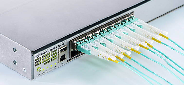
A significant increase in the number of applications supported by data centers has resulted in more cables and connections than ever, making available space a foremost concern. As a result, higher-density solutions like MTP/MPO connectors and multi-fiber cables that take up less pathway space than running individual duplex cables become more popular.

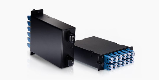
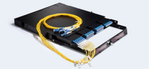
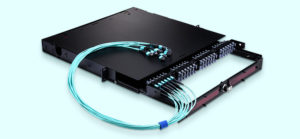
Since few manufacturers offer field-installable MTP/MPO connectors, many data center managers are selecting either multi-fiber trunk cables with MTP/MPOs factory-terminated on each end, or fusion splicing to pre-terminated MTP/MPO or multi-fiber LC pigtails. When you select trunk cables with connectors on each end, data center managers often specify lengths a little bit longer because they can’t always predict exact distances between equipment and they don’t want to be short. However, they then have to deal with excess slack. When there are thousands of connections, that slack can create a lot of congestion and limit proper air flow and cooling. One alternative is to purchase a multi-fiber pigtail and then splice to a multi-fiber cable.

Inside the data center and in the enterprise LAN, 12-fiber MPO connectors provide a convenient method to support higher 40G and 100G bandwidth. Instead of fusing one fiber at a time, another type of fusion splicing which is called ribbon/mass fusion splicing is used. Ribbon/mass fusion splicing can fuse up to all 12 fibers in one ribbon at once, which offers the opportunity to significantly reduce termination labor by up to 75% with only a modest increase in tooling cost. Many of today’s cables with high fiber count involve subunits of 12 fibers each that can be quickly ribbonized. Splicing those fibers individually is very time consuming, however, ribbon/mass fusion splicers splice entire ribbons simultaneously. Ribbon/mass fusion splicer technology has been around for decades and now is available in handheld models.

Ribbon/Mass Fusion Splicer

Conclusion
Fusion splicing provides permanent low-loss connections that are performed quickly and easily, which are definite advantages over competing technologies. In addition, current fusion splicers are designed to provide enhanced features and high-quality performance, and be very affordable at the same time. Fiberstore provides various types and uses of fusion splicers with high quality and low price. For more information, please feel free to contact us at sales@fs.com.