Tag Archives: MPO Cables

How to Ensure MTP/MPO Polarity of the Patch Cable Is Always Right?

Share

As we know, in order to ensure the right MTP/MPO polarity, transmit signal (Tx) at one end of the cable must match the corresponding receiver (Rx) at the other end of the cable. In some complex cabling deployment, it seems not much simple. Now this article may give you some golden rules to help you ensure the right MTP/MPO polarity of Patch Cables.

You’d Better Use the Same Type Patch Cable
When fiber optic patch cables have different polarity (for example, MTP or MPO polarity), we must to be very careful when replacing patch cables in our network. If you don’t understand polarity and use the wrong polarity patch cables, it may influence the transmission the damage your device. To decrease this risk, we recommend that you’d better use the same patch cables in your network.

Type A/B LC Duplex and Type B Female-to-Female MPO Patch Cables Are Common
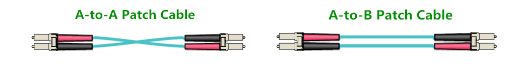
Two types of duplex fiber patch cord are defined in the TIA standard: A-to-A (cross-over) type and A-to-B (straight-through) type. Note: A-to-A patch cords are not commonly deployed and should be used only when necessary as part of a polarity method (See ANSI/TIA-568-C.0).

Type A/B LC Duplex cable

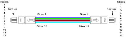
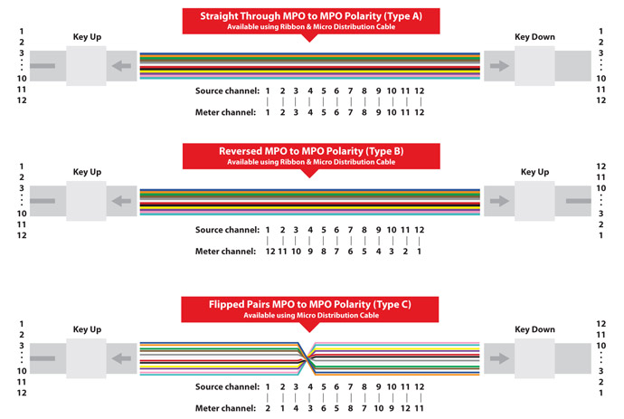
The three methods for proper polarity defined by TIA 568 standard are named as Method A, Method B and Method C. To match these standards, three type of MPO trunk cables with different structures named Type A, Type B and Type C are being used for the three different connectivity methods respectively. As shown in the figure below, type A MPO cables just like the A-to-A duplex cables, Tx can’t match the Rx. Type C MPO cables use a pair flip design, which aren’t suitable for 40GBASE-SR4 and 100GBASE-SR4 standard. Therefore, we should use Type B MPO cables for connection.

MPO_to_MPO_Polarity
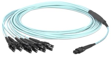
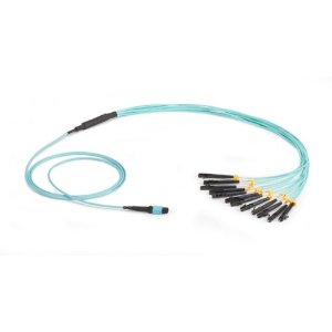
For MTP/MPO cables, gender is a big problem. MTP/MPO interfaces on optical transceivers are always male (pinned). To avoid damage to the optical module, MTP/MPO polarity must always be female-to-female (unpinned). Besides, there is a rule must be obeyed if we want to connect an MPO patch cable to another cable. That is a male patch cable must be connected to a female patch cable. Never connect a male to a male one or a female to a female one.

MPO patch cable male female polarity

Three Connection Methods Help Keep the Right MTP/MPO Polarity
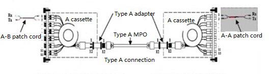
1. Type A connection
One end of Type A MPO/MTP patch cord is A-B normal patch cord, the other end A-A. Between MPO/MTP patch cord and normal patch cord is Type A MPO/MTP cassette and Type A MPO/MTP adapter (The two keys of type A adapter is opposite levels)

Type A connection

2. Type B connection
Both ends of Type B MPO/MTP patch cord are A-B normal patch cord. Between MPO/MTP patch cord and normal patch cord is Type B MPO/MTP cassette and Type B MPO/MTP adapter (The two keys of type B adapter is same level)

Type B connection

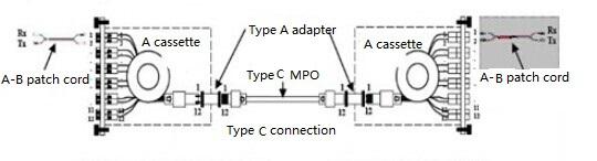
3. Type C connection
Both ends of Type C MPO/MTP patch cord are A-B normal patch cord. Between MPO/MTP patch cord and normal patch cord is Type A MPO/MTP cassette and Type A MPO/MTP adapter (The two keys of type A adapter is opposite levels)

Type C connection

All kinds of duplex patch cables and MPO patch cables are available and in stock for same-day shipping in FS.COM. For more information, you can contact us at sales@fs.com.

Related Article:

Unveil Polarity of MTP/MPO Multi-Fiber Cable Solutions

Polarity and MPO Technology in 40/100GbE Transmission

Signal Crossover in Fiber Optic Systems With MPO Cables

Share

Ribbon cables terminated with MPO connetors present some challenges when it comes to maintaining the correct signal crosssover in a segment consisting of multipe fiber optic srands. The ANSI/TIA-568-C.3 standard provies a set of “Guidelines for Maintaing Polarity Using Array Connetors” that decribe three types of MPO-to-MPO array cables, defined as Types A, B, and C. These cables are used to provide three different methods for maintaining a crossover connection. Method A is prefferred method, and is based on Type A MPO Fiber cables.

Figure 17-6 shows a Type A straight through ribbon cable with 12 fibers terminated in MPO connetor. A Method A backbone link is cabled “straight through”, terminating in the cabling system patch panel. One end of the link will have a straight through patch cable, connetion from the patch panel to the Ethernet interface. The other end of the link will have a crossover cable connecting to the Ethernet interface. The guidelines recommend keeping all of the crossover patch cables at one end of the link, to keep the system as simple as possible and help the installer to avoid connecting the wrong type of patch cale.

MPO Fiber

The guidelines also show Method B and Method C, which are two methods for providing a crossover patch built into the MPO backbone cables themselves. Given the complexity of these approaches and the difficulty of implementing them correctly, they are both rarely used.

As you can see, there are a variety of approaches to managing the signal crossover for the 12-fiber and 24-fiber systems needed to support 40 and 100 Gb/s Ethernet. For the best results, make sure you know which method your site is using in the cabling system, and order the correct MPO cable types to make the connections and achieve the signal crossover. Note that some vendors provide special MPO connectors that make it possible to change connector gender and polarity(crossover) in the field, which coulde be a handy way to resolve MPO-to-MPO connectivity issues.

To provide an introduction and basic information to readers, this section begins with a presentation of the components needed for a parallel optical MPO connection.

MPO connectors contact up to 24 fibers in a single connection. A connection must be stable and its ends correctly aligned. These aspects are essential for achieving the required transmission parameters. A defec-tive connection may even damage components and or cause the link to fail altogether.

MPO cables are delivered already terminated. This approach requires greater care in planning in advance but has a number of advantages: shorter installation times, tested and guaranteed quality and greater reli-ability.

Fiber trunk cables serve as a permanent link connecting the MPO modules to each other. Trunk cables are available with 12, 24, 48 and 72 fibers. Their ends are terminated with the customer’s choice of 12-fiber or 24-fiber MPO connectors.

trunk fiber optic cables

Harness cables provide a transition from multi-fiber cables to individual fibers or duplex connectors.The 12-fiber harness cables available from R&M are terminated with male or female connectors on the MPO side, the whips are available with LC or SC connectors.

Harness cable

Fiberstore supply MTP MPO fiber cables, MTP Cassette and MPO Cassette.  MTP MPO cables are available in 4,8,12, 24, and 48 fiber array configurations.  Many additional options and combinations are available. All fiber optic cables are customizable.