Author Archives: Alice.Gui

How to Choose the Right Rack Mount Fiber Enclosure?

Share

Fiber enclosure can provide easy-to-manage cabling environments and strong protection for fiber optic cables. Since more and more cables used in today’s data centers, high-density cable management tools also become more popular and essential than before. However, there are so many fiber enclosure manufacturers and suppliers, and the rack mount fiber enclosures supplied therefore available in different sizes and applications. How to choose the rack mount fiber enclosures for your network?

Rack Mount Enclosures Configurations
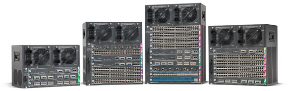
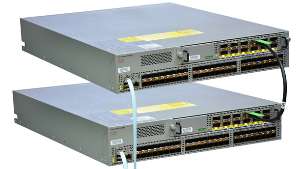
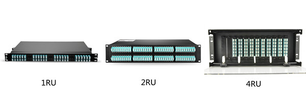
The rack mount enclosure is generally made for standard 19 inch rack mounting. Depending on the number of connections required, they are available in one or more rack units (RU) height configurations, such as 1RU, 2RU or 4RU, etc. See the picture below, you should choose the most proper one depending on space and port requirement of your network.

fiber enclosures

Rack Mount Enclosures Mount Types
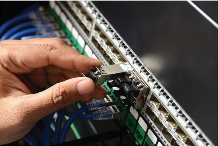
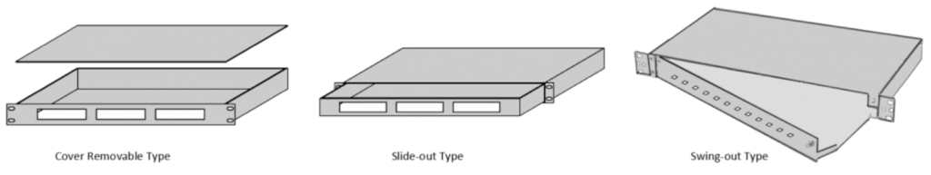
1RU rack mount fiber enclosures are the most commonly used size in data center server racks cable management. For convenient installation and cable management, there are cover removable, slide-out and swing-out three mount types fiber enclosures to choose from. The cover removable type is an early type of fiber enclosures. If your budget is sufficient, I will recommend you to use the slide-out type or swing-out type though they are more expensive than the cover removable type. But you may get more benefits during installation and maintenance, as they respectively feature a convenient slide-out support tray and an integrated swing-out tray so that you don’t need to remove the whole enclosure from the rack to gain internal access.

222

Rack Mount Fiber Enclosures Applications
Fiber enclosure has various designs and applications. There are mainly three ways to use the fiber enclosures, which are depended on the accessories that are installed on the fiber enclosure. The following will take a slide-out 1RU rack mount fiber enclosure as example to illustrate the applications of the fiber enclosures in data center. Installed with splice trays, fiber adapter panels and MTP cassettes separately, fiber enclosure can provide cabling environment for different connections.

Application 1: Installing splice tray and FAPs
Installing four fiber adapter panels on the front panel and one or more splicing trays inside the enclosure drawer. This fiber enclosure can provide cable management and protection for splicing joints and connections.

splice tray and fiber adapter panels
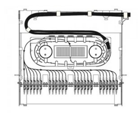
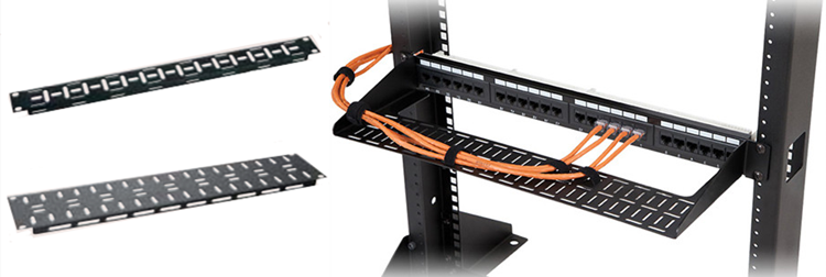
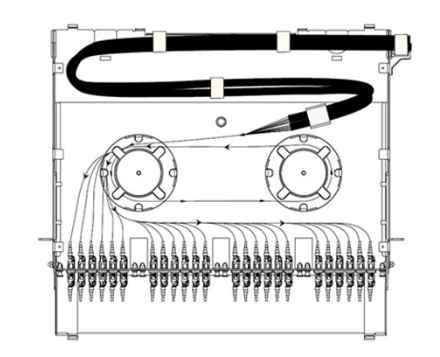
Application 2: Installing Spools and FAPs
Installing two spools on the enclosure drawer and four FAPs on the front panel, this fiber enclosure can provide flexible high density cabling for fiber patch cables.

Spools and fiber adapter panels
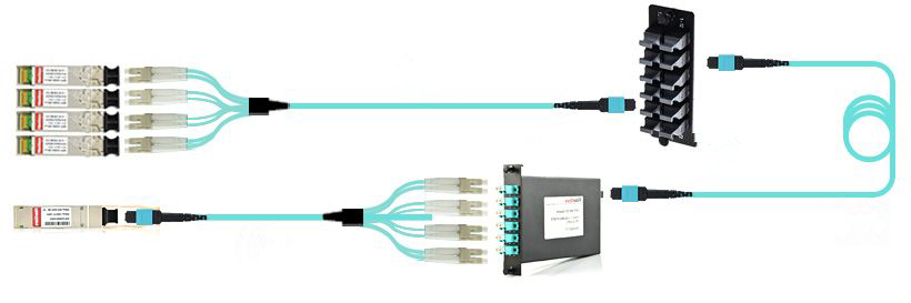
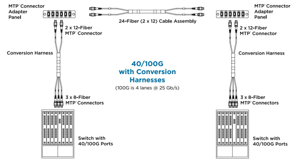
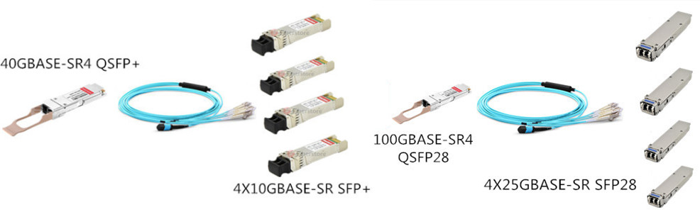
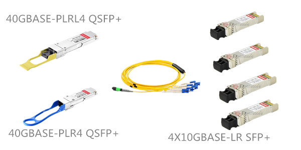
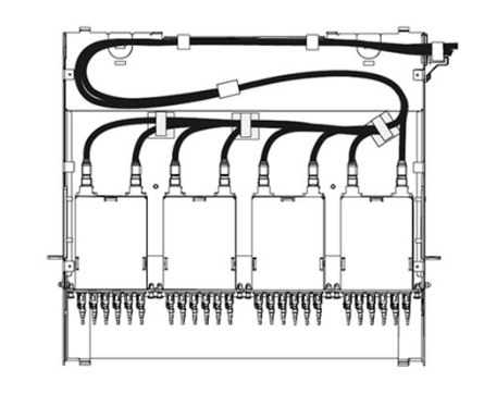
Application 3: Installing HD MTP Cassettes
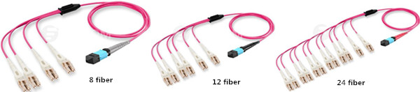
Up to four MTP Cassettes can be installed in this 1U fiber enclosure, which can provide 40G/100G to 10G high cabling density and easy transferring from MTP interface to LC interface.

MTP Cassettes

Conclusion
After reading the passage, we know that rack mount fiber enclosures may be available in different sizes, mount types and applications. Thus to choose a right fiber enclosure seems not a simple thing. FS.COM offers a wide range of rack mount enclosures, as well as custom service, which can help address all kinds of your requirements. For more details, please contact us via sales@fs.com or call 24/7 Customer Service: 1 (718) 577 1006.

Related Article: Upgrade to 40G / 100G Networks with High-Density Fiber Enclosures

Why Not Use Cable Lacing Bars to Manage Your Messy Cables?

Share

Cable lacing bars, also called lacer bars, consist of a metal bar that mounts to the rear of a standard 19″ rack or cabinet, behind a patch panel. These bars provide support and management of cables that are secured to the bar with cable ties or adjustable clips. Each cable lacing bar occupies 1/3 to 2/3 of a rack space and can secure and manage up to 24 cables in 1 RU. They are usually used to support and manage cables in telecommunication rooms, which provide strain relief, bend radius control, superior aesthetics and improve organisation and routing of cable.

cable lacing bars

How to Use the Cable Lacing Bars?
In fact, the process of installing a cable lacing bar is very easy. As shown in the figure below, we only need to install the cable lacing bar to the rack firstly, and then use the cable tie to fix the cables to the cable lacing bar.

lacing bars

Which Type Cable Lacing Bars Should I Choose?
In order to meet different cabling management needs, there are also many different cable lacing bars available in the market. Below some common cable lacing bars are listed, and you can choose the right one for your network according to your specific cabling environment.
1. Round Lacer Bars
Use the 1RU round lacer bar when a small profile is required and for lacing small or individual horizontal cable runs. 1/4” diameter rod with flattened ends.

Round Lacer Bars
2. Rectangular Lacer Bars
Use the 1RU aluminum lacer bar when lacing cables vertically or horizontally. Aluminum construction provides the ability to drill holes to attach tie saddles, mount electrical boxes, etc. This lacer bar can also be used to support the rear of equipment. 1/4” diameter rod with flattened ends.

Rectangular Lacer Bars
3. L-Shaped Lacer Bars
“L” shaped lacer bars are strong and provide fixed tie points. Recommended for larger runs of cable. They are available in 2”, 4” and 6” offset. Choose the appropriate offset bar based on the distance from the rear of equipment to the rack rail.

L-Shaped Lacer Bars
4. Round Lacer Bars with Offset
Use the round lacer bar with offset when lacing small bundles or individual cables off the rear of equipment, patch panels and other components to relieve cable stress from the connections. They are available in 1.5” offset and 4” offset respectively (figure below). Choose the appropriate offset based on the distance from the rear of equipment to the rack rail. 1/4” diameter rod with flattened ends.

Round Lacer Bars with Offset
5. 90º Bend Lacer Bars
These 90° bend offset lacer bars are similar to other offset round lacer bars, but feature 90° bends to provide full-width support. Can also be used to provide clearance around components that extend past the rear rack rail (16-5/8” open width). 1/4” diameter rod with flattened ends.

90º Bend Lacer Bars
6. Horizontal Lacer Panel
Use the horizontal lacer panel for lacing large amounts of cable or mounting devices. Two rack space high, the horizontal lacer panel features a large flange, numerous cable tie points and more surface for mounting.

Horizontal Lacer Panel

Cable lacing bars are a useful and cost effective cable management solution for rack or enclosure systems. These bars are essential in helping avoid cable strain especially when trying to run cables from one side of the enclosure to the other. FS.COM offers a full line of cable lacing bars to fit a variety of applications offering end users flexibility and convenience to prevent cable strain. Higher density applications may be addressed with FS.COM cable manager.

Three Kinds of Polarity Reversal Methods of LC Uniboot Patch Cords

Share

As the networking environment of today becomes increasingly dependent on high-speed and high-density solutions, effective cable management is a real problem. The challenge is how to manage more cables in a smaller amount of space. The LC uniboot patch cord utilises a special “round duplex” cable that allows duplex transmission within a single 2.4mm or 3.0mm cable, which reduces cable management space by up to 70% comparing to standard LC patch cords. Besides, it has a unique polarity reversal design allows the fiber polarity to be easily switched without the use of any tools. In today’s LC uniboot patch cords market, there are usually three methods to reverse the polarity.

Method One
1. Open connector top.

11
2. Switch the polarity.

22
3. Close connector top.

33

Method Two
1. Locate trigger housing on LC uniboot connector and pull towards the boot.

1
2. Open trigger housing is resting on the boot turn each LC connector to the outside 180 degrees one at a time.

888
3. Complete the polarity reversal by turning the resting trigger housing 180 degrees around boot and click into LC until you hear a click.

000

Method Three
1. Connector Polarity
Uncrossed lines under the connector latch on the housing at both ends indicates uncrossed fiber polarity A-B/B-A.

1
2. Unlock Front Housing on One End
Push the keys on either side to unlock the housing to remove the front section of the Uniboot housing.

2

3. Remove Front Housing
Slide the front housing away from the rest of the Uniboot.

3
4. Rotate Front Housing
Flip the released section of the housing. Do not rotate or twist the fiber.

4
5. Attach Front Housing
Push the housing back over the ends and the rest of the Uniboot connector until it clicks back into place.

5
6. Connector Polarity
Finished result should now show crossed lines under the flipped connector latch and uncrossed lines on the unaltered end. This would indicate a crossed fiber polarity A-A/B-B.

6

Different kind of LC uniboot patch cords may have different polarity reversal design, therefore we must use different method to change the polarity. When you choose to use LC uniboot patch cords in your network, keep in mind to take the polarity reversal methods in to consideration. FS.COM LC uniboot patch cords (easily reverse the polarity with method one) terminated with premium grade zirconia ceramic ferrule connectors which help assure high transmission quality and low optical power loss and offer improved airflow and visibility of equipment within a high-density network environment.

How to Choose SFP+ Transceivers for Cisco 4500 Series Switch

Share

The Cisco 4500 series switches provide high performance, mobile, and secure user experiences through Layer 2-4 switching investments. Since they have a centralized forwarding architecture that enables collaboration, virtualization, and operational manageability through simplified operations, therefore, more and more people choose to use 4500 series switch in their network. As we know, once we use a network switch, we may use some transceiver modules. In this article, some SFP+ transceivers that supported for Cisco 4500 series switch will be introduced.

Cisco 4500 Series Switch Overview
Cisco 4500 series switch include 4500 Series and 4500E Series switch. Among, 4500 series include Catalyst 4503 Switch, Catalyst 4506 Switch, Catalyst 4507R Switch, Catalyst 4510R Switch. With forward and backward compatibility spanning multiple generations, the new Cisco Catalyst 4500E Series provides exceptional investment protection and deployment flexibility to meet the evolving needs of organizations of all sizes, which include Catalyst 4503-E Switch, Catalyst 4506-E Switch, Catalyst 4507R+E Switch and Catalyst 4510R+E Switch. SFP+ ports operate in full-duplex mode and are present on the WS-X4516-10GE and WS-X4013+10GE supervisors, as well as some line cards. These ports use the 10GBASE-SR, 10GBASE-LRM and 10GBASE-LR SFP+. SFP+ connectors vary with interface type and may use multimode fiber (MMF) or single-mode fiber (SMF) cable.

cisco 4500

Supervisor Engine for Cisco 4500 Series Switch
The Cisco supervisor engine is the brain of many of Cisco’s switches, which refers to specific modules that can be placed in a modular chassis. Cisco 4500 series and 6500 series switch both require supervisor engines to work. In fact, the transceivers type depends on the port type of supervisor engine. So, it’s necessary to identify the port type of your supervisor engines first. In following table, I display some supervisor engines that both supported for Catalys 4500 series switch and SFP+ transceivers. Please note that WS-X4516-10GE, WS-X4013+10GE, WS-X45-Sup6-E, WS-X45-Sup6L-E and WS-X4606-X2-E can also be used for X2 transceivers with CVR-X2-SFP10G converter.

Cisco Catalyst 4500 Series Supervisor Engine V-10GE
WS-X4516-10GE 2×10 Gigabit Ethernet (X2 or SFP+) or 4X1 Gigabit Ethernet (SFP)
Cisco Catalyst 4500 Series Supervisor Engine II-Plus-10GE
WS-X4013+10GE 2x10GE (X2 or SFP+) and 4×1 Gigabit Ethernet (SFP)
Cisco Catalyst 4500E Supervisor Engine 6-E And 6L-E
WS-X45-Sup6-E 2×10 Gigabit Ethernet (X2 or SFP+) or 4×1 Gigabit Ethernet (SFP), Console RJ-45, USB
WS-X45-Sup6L-E 2×10 Gigabit Ethernet (X2 or SFP+) or 4×1 Gigabit Ethernet (SFP), Console RJ-45
Cisco Catalyst 4500E Series Line Cards
WS-X4606-X2-E 6×10 Gigabit Ethernet (X2 or SFP+)
WS-X4712-SFP+E 12×10 Gigabit Ethernet (SFP+)
Cisco Catalyst 4500E Series Supervisor Engine 7-E And 7L-E
WS-X45-SUP7-E 4×10 Gigabit Ethernet uplinks (SFP+)
WS-X45-SUP7L-E 2×10 Gigabit Ethernet uplinks (SFP+) or 4×1 Gigabit Ethernet uplinks (SFP)
Cisco Catalyst 4500E Series Supervisor Engine 8-E And 8L-E
WS-X45-SUP8-E 8×10 Gigabit Ethernet uplinks (SFP+)
WS-X45-SUP8L-E 4×10 Gigabit Ethernet uplinks (SFP+) or 4×1 Gigabit Ethernet uplinks (SFP)

SFP+ Transceivers for Cisco 4500 Series Switch
According to Cisco 10-Gigabit Ethernet Transceiver Modules Compatibility Matrix, all supervisor engines mentioned above can support SFP-10G-SR, SFP-10G-LRM, SFP-10G-LR, SFP-10G-SR-S and SFP-10G-LR-S SFP+ transceivers. Besides, WS-X4712-SFP+E, WS-X45-SUP7-E, WS-X45-SUP7L-E, WS-X45-SUP8-E and WS-X45-SUP8L-E can also support SFP-10G-ER, SFP-10G-ZR, SFP-10G-ER-S and SFP-10G-ZR-S SFP+ transceivers. All SFP+ transceievrs can be found in FS.COM.

WS-X4516-10GE, WS-X4013+10GE, WS-X45-Sup6-E, WS-X45-Sup6L-E, WS-X4606-X2-E, WS-X4712-SFP+E, WS-X45-SUP7-E, WS-X45-SUP7L-E, WS-X45-SUP8-E and WS-X45-SUP8L-E
SFP-10G-SR Cisco SFP-10G-SR Compatible 10GBASE-SR SFP+ 850nm 300m DOM Transceiver, $ 16
SFP-10G-LRM Cisco SFP-10G-LRM Compatible 10GBASE-LRM SFP+ 1310nm 220m DOM Transceiver, $ 34
SFP-10G-LR Cisco SFP-10G-LR Compatible 10GBASE-LR SFP+ 1310nm 10km DOM Transceiver, $ 34
SFP-10G-SR-S Cisco SFP-10G-SR-S Compatible 10GBASE-SR SFP+ 850nm 300m DOM Transceiver, $ 16
SFP-10G-LR-S Cisco SFP-10G-LR-S Compatible 10GBASE-LR SFP+ 1310nm 10km DOM Transceiver, $ 34
WS-X4712-SFP+E, WS-X45-SUP7-E, WS-X45-SUP7L-E, WS-X45-SUP8-E and WS-X45-SUP8L-E
SFP-10G-ER Cisco SFP-10G-ER Compatible 10GBASE-ER SFP+ 1550nm 40km DOM Transceiver, $ 180
SFP-10G-ZR Cisco SFP-10G-ZR Compatible SFP+ 1550nm 80km DOM Transceiver, $ 400
SFP-10G-ER-S Cisco SFP-10G-ER-S Compatible 10GBASE-ER SFP+ 1550nm 40km DOM Transceiver, $ 180
SFP-10G-ZR-S Cisco SFP-10G-ZR-S Compatible 10GBASE-ZR SFP+ 1550nm 80km DOM Transceiver, $ 400

Related Articlea:

How to Choose SFP+ Transceivers for Cisco 4500 Series Switch

Cisco SFP-10G-SR: All You Need to Know


Unveil Polarity of MTP/MPO Multi-Fiber Cable Solutions

Share

With widespread deployment of 40G and 100G networks, high-density MTP/MPO cable solutions are also become more and more popular. Unlike traditional 2‐fiber configurations LC or SC patch cords, with one send and one receive, 40G & 100G Ethernet implementations over multimode fibers use multiple parallel 10G connections that are aggregated. 40G uses four 10G fibers to send and four 10G fibers to receive, while 100G uses ten 10G fibers in each direction. MTP/MPO cable can hold 12 or 24 fibers in a connector, which greatly facilitates the upgrade to 40G and 100G networks. However, since there are so many fibers, the polarity management of the MTP/MPO cable may be a problem.

Structure of MTP/MPO Connectors
Before explaining the polarity, it is important to learn about the structure of MTP/MPO connector first. Each MTP connector has a key on one side of the connector body. When the key sits on top, this is referred to as the key up position. In this orientation, each of the fiber holes in the connector is numbered in sequence from left to right. We will refer to these connector holes as positions, or P1, P2, etc. Each connector is additionally marked with a white dot on the connector body to designate the position 1 side of the connector when it is plugged in.

666

Structure of MTP/MPO Adapters
Since the MTP connectors can either key up and key down, there are two types of MPO adapters.

  • Type A: Key-up to key-down

Here the key is up on one side and down on the other. The two connectors are connected turned 180° in relation to each other.

  • Type B: Key-up to key-up

Both keys are up. The two connectors are connected while in the same position in relation to each other.

555

Two Polarity of Traditional Duplex Patch Cable
Classic duplex cables are available in a cross-over version (A-to-A) or a straight-through version (A-to-B) and are terminated with LC or SC connectors. Telecommunications Cabling Standard defines the A-B polarity scenario for discrete duplex patch cords, with the premise that transmit (Tx) should always go to receive (Rx) — or “A” should always connect to “B”. Therefore, A-B polarity duplex is very common in applications.

777

Three Polarity of MTP/MPO Multi-Fiber Cable
Unlike traditional duplex patch cables, there are three polarity for MTP/MPO cables: polarity A, polarity B and polarity C.

  • Polarity A

Polarity A MTP cables use a key up, key down design. Therefore, as shown in the figure below, the position 1 of one connector is corresponding to the position 1 of another connector. There is no polarity flip. Therefore, when we use polarity A MTP cable for connection, we must use A-B duplex patch cables on one end and A-A duplex patch cables on the other end. Since in this link, Rx1 must connect to Tx1. If we don’t use A-A duplex patch cable, according to the design principle of polarity A MTP cable, fiber 1 may transmit to fiber 1, that is to say Rx1 may transmit to Rx1, which may cause errors.

111

  • Polarity B

Polarity B MTP cables use a key up, key up design. Therefore, as shown in the figure below, the position 1 of one connector is corresponding to the position 12 of another connector. Therefore, when we use polarity B MTP cable for connection, we should use a A-B duplex patch cables on both ends. Since the key up to key up design help to flip the polarity, which makes fiber 1 transmit to fiber 12, that is the Rx1 transmits to Tx1.

222

  • Polarity C

Like the polarity A MTP cables, polarity C MTP cables also use a key up, key down design. However, within in the cable, there is a fiber cross design, which makes the position 1 of one connector is corresponding to the position 2 of another connector. As shown in the figure below, when we use polarity C MTP cable for connection, we should use a A-B duplex patch cables on both ends. Since the cross fiber design help to flip the polarity, which makes fiber 1 transmit to fiber 2, that is the Rx1 transmits to Tx1.

333

Conclusion
Different polarity MTP cables may have different connection methods. No matter which type cable you choose, remember its design principle and choose the right cabling infrastructure for your network. FS.COM provides a full range of MTP cables and MTP cassettes,  polarity A, B and C are all available.

SFP+ Fiber vs SFP+ Twinax Cable vs 10GBASE-T, Which to Choose for 10G?

Share

When you’ve selected the server, storage and switch to setup your data center, then how do you connect it all together? There’s no doubt that the answer is “with cables.” Let’s look at the three most common cables that used to connect the servers and storage to switches in a 10G network. They are SFP+ fiber solution (used with LC fiber patch cable), SFP+ twinax cable and 10GBASE-T solution. Which one should you choose? Let’s find the answer together!

SFP+ Fiber Solution
This connection methods requires two things on each device: 10G pluggable SFP+ transceiver and fiber optic patch cable. Once these are in place on both devices (server and switch), you can plug the patch cords into the transceiver on both sides. These SFP+ optical transceivers use approximately 1W per transceiver and have a latency of less than 0.1 microsecond. SFP+ transceiver comes in different types to drive signals across fiber optic cables with different maximum distances. The most common, and lowest in cost, is 10GBase-SR, which can span 300 meters. Other types can reach as far as 100 kilometers.

SFP+ transceivers

Pros: This connectivity method supports fiber cables that are really long, allowing you to connect a server at one end of a data center to a switch several racks away or even at the other end.
Cons: Pluggable transceiver parts are quite expensive.

SFP+ Twinax Cable
SFP+ twinax direct attach cable (DAC) integrates transceivers with twinax cable into an energy efficient, low-cost, and low-latency solution. It features SFP+ connectors on both ends, thus eliminating the need for expensive SFP+ transceivers. SFP+ twinax cables use only 1.5 watts of power per port and introduce only approximately 0.25 microsecond of latency per link. This makes it an optimal solution for handling high bandwidth transmission within short distances such as inside energy-efficient data centers.

SFP+ Twinaxial Cable

Pros: Lower latency, lower power and lower heat.
Cons: Transmission distance is usually less than 10 meter.

10GBASE-T Solution: Cat6 Copper Cable
This option probably looks familiar – like the RJ-45 ports and cabling you use to connect your laptop to a normal network jack. The difference is that you need specialized network adapters with ports that support faster 10G throughput. Cat6 cables have more individual copper wires, twisted tighter, with better shielding to prevent outside signal interference. They cost more than CAT5 but ensure better signal communication, which is a requirement to speed up to 10G. Cat6 copper cables use 5 watts of power per port and introduce approximately of latency per link, which is much higher than SFP+ optics and SFP+.

10GBASE-T structured-cabling

Pros: Longer distance – 100 meters. Backward compatibility to 1 gigabit Ethernet or 100 megabit Ethernet
Cons: Higher latency, higher power and higher heat. Not many data center switches support 10GBASE-T ports.

Conclusion
Vita differences of these three 10G cabling solutions are displayed in the table below. According to your demands to choose the right one.

Name Transmission Distance Latency Power
SFP+ Fiber Solution 300 m – 100 km 0.1 microsecond 1 watts
SFP+ Twinax Cable 10 m 0.25 microsecond 1.5 watts
10GBASE-T Solution 100 m 2.6 microsecond 4 – 6 watts

Three Types MTP Harness Cables Used in Today’s Data Center

Share

As we know, harness cables are generally used to connect high-density switches with LC serial transceivers installed. The transition harness connects to the pre-installed MTP backbone trunk cable and then furcates to LC connectors entering the switch. This kind of MTP-LC harness cables are usually supplied in short lengths because they are normally only used for “in-rack” connections. Transition harnesses are available for Base-8, 12 and 24 backbones and the LC tails are numbered for clear port identification and traceability.

MTP Harness Cable

Application Scene

MTP-LC harness cables application

Another harness cable type is conversion harness cables, which allow users to convert their existing MTP backbone cables to an MTP type which matches their active equipment. Conversion harnesses are a low-loss alternative to conversion modules because they eliminate one mated MTP pair across the link. Many of today’s legacy infrastructures are built using a Base-12 MTP backbone design, however experience shows us that this connector is rarely used on higher data rate switches or servers. Currently Base-8 is the preferred connector for 40G (SR4) transceivers and Base-24 is the preferred connector for 100G transceivers (SR10).

MTP Harness Cable

The final type of harness cable is MTP trunk harness cables. MTP trunk harness cables are high density multi-stranded cables which form the backbone of the data center. This kind of trunk harness cables are available in different fiber-counts up to 144 fibers, which reduce the installation time by consolidating multiple sub-units into a single cable. This approach significantly reduces the overall diameter of the cable and provides much better space utilization of cable routing channels. Just as two types harness cables mentioned, the MTP trunk harness cables are also available with 8, 12 and 24 fiber sub-units so that users can deploy Base-8, Base-12 or Base-24 infrastructures to suit their MTP connectivity requirements.

MTP harness cable

Conversion and Trunk harness Cable Application

Conversion-and-Trunk-harness-cable-Application

QSFP+ and QSFP28 Transceivers Cabling Solutions

Share

The short range 40-Gigabit Ethernet QSFP+ and 100-Gigabit Ethernet QSFP28 transceivers that are widely used in today’s data center use 12-fiber patch cables with female MPO connectors. The fiber can be either OM3 or OM4. The long range QSFP+ and QSFP28 transceiver use single-mode fiber patch cables with duplex LC connectors. This article may introduce the cabling solutions for QSFP+ and QSFP28 transceiver to you.

QSFP+ and QSFP28 Transceiver Types
In terms of 40G QSFP+ transceivers, from short range to long range, they are available in 5 common types. The minimum transmission distance is 100m, and the max transmission distance is 40km. 100G QSFP28 transceivers are commonly avaiable in 100GBASE-SR4 and 100GBASE-LR4 two types. Detailed QSFP+ and QSFP28 transceiver specifications are displayed in following tables.

Transceiver Type Interface Standard Connector Type Fiber Type
QSFP+ 40GBASE-SR4 Female MTP/MPO, key up 12-fiber multi-mode fiber (MMF) (OM3 or OM4)
QSFP+ 40GBASE-PLRL4 Female MTP/MPO, key up 12-fiber single-mode fiber (SMF) 1km
QSFP+ 40GBASE-PLR4 Female MTP/MPO, key up 12-fiber SMF 10km
QSFP+ 40GBASE-LR4 LC duplex SMF 10km
QSFP+ 40GBASE-ER4 LC duplex SMF 40km
QSFP28 100GBASE-SR4 Female MTP/MPO, key up 12-fiber MMF (OM3 or OM4)
QSFP28 100GBASE-LR4 LC duplex SMF 10km

12-Fiber Patch Cables with MTP Connectors
12-fiber patch cables with MTP connectors can be used to connect two transceivers of the same type—40GBASE-SR4-to-40GBASESR4 or 100GBASE-SR4-to-100GBASE-SR4. You can also connect 4x10GBASE-LR transceivers such as 40GBASE-PLRL4 and 40GBASE-PLR4 using patch cables—4x10GBASE-LR-to-4x10GBASE-LR—instead of breaking the signal out into four separate signals. Ensure that you order cables with the correct polarity. The MTP connectors on the 12-fiber cables should be key up (sometimes referred to as latch up, Type B, or Method B). If you are using patch panels between two QSFP+ or QSFP28 transceivers, ensure that the proper polarity is maintained through the cable plant.

12-Fiber MTP Patch Cables

12-Fiber MPO Patch Cables

12-Fiber Breakout Cables with MTP-LC Duplex Connectors
12-fiber breakout cables with MTP-LC duplex connectors can be used to connect a 4x10GBASE-LR or 4x10GBASE-SR transceiver to four separate 10GBASE-LR or 10GBASE-SR SFP+ transceivers. The breakout cable is constructed out of a 12-ribbon fiber-optic cable. The breakout cable splits from a single cable with an MTP connector on one end, into 4 cable pairs with 4 LC duplex connectors on the opposite end.

40G QSFP+ and 100G QSFP28 transceivers solution

40G to 4×10G

LC Duplex Patch Cables
Single-mode patch cables with LC duplex connectors can be used to connect two transceivers of the same type—40GBASE-LR4-to-40GBASE-LR4 or 100GBASE-LR4-to100GBASE-LR4. The SMF patch cable is one fiber pair with two LC duplex connectors at opposite ends.

LC Duplex Patch Cables

Related Article: Can I Use the QSFP+ Optics on QSFP28 Port?

Data Center Upgrade — Who Should Be Responsible for Buying Transceivers?

Share

There was a time that cable products specifically associated with hardware OEMs. If a company was buying or using one of these vendors’ products, the matching cables also had to be used. Therefore, whoever was responsible for managing the hardware was also responsible for the cabling used to connect the devices together. Then, the structured cabling industry replaced this. The cabling infrastructure is now viewed as an independent asset separate from the IT hardware. This has allowed companies to make purchasing decisions for IT and cabling without the concern of each other. But this may be a problem. To understand the problem, let’s understand the LAN network operation principles first.

transceiver

The OSI Model of LAN Network
As we know, the operation of local area networking (LAN) was defined with the Open Systems Interconnection Reference Model (OSI Model). The OSI Model defined seven layers of operation. By using the model, the industry could develop networking functions in a modular fashion and still ensure interoperability. The bottom of the stack is Layer 1, the Physical Layer. Layer 1 includes the cabling that is used to connect the various pieces of equipment together so that the data can be transported. The next step up on the stack is Layer 2, the Data Link Layer. Layer 2 provides for addressing and switching, so that the data can be sent to the appropriate destination. Layer 3 is the Network Layer, where data can be routed to another network. Layers 4 through 7 deal with software implementations.

OSI Model
The OSI Model meant that an end-user could purchase software (Layer 7) and expect it to work on multiple vendors’ hardware (Layer 2). And the hardware could be connected using multiple vendors (Layer 1). Structured cabling now had a home within Layer 1. Then this module leads to division of responsibility, for cabling versus network design specifications. The end-user ended up having “cabling people” and “networking people” on their staff. Each group of people used their own set of vendors and supply chains to specify and source their materials. And they each only needed a very basic understanding of what the other people were doing. This system has worked very well for the enterprise LAN. So what’s the problem?

What Is the Problem?
In the 1990s, copper cable was widely used in data center cabling deployment. As time went on, optical fiber cable was added. In fiber switches, it is common to use pluggable transceivers. This is done for a variety of reasons, but one is cost. Even though a transceiver is plugged into a switch, it is part of the OSI Model’s Layer 1, the Physical Layer. Additionally, most of the transceiver is part of the Physical Media Dependent (PMD) portion of Layer 1, as illustrated here. This means that the transceiver and the cable types must match.

transceiver Physical Media Dependent
However, unlike copper, there was never a fixed standard on the connector type or channel distance. Fiber may have many different standards and connector options. With multiple fiber types, multiple operating wavelengths, and multiple connectivity options, the number of solutions seemed limitless. Since the transceiver is physically plugged into the switch, it has always been considered the networking group’s responsibility. “Networking people” are responsible for buying transceivers and “cabling cable” are responsible for buying cabling products, then this causes the problem. Let’s take the following real-life case for example.

Real-life Case and Solution
Company A has a data center. Marsha is the facilities manager and is responsible for the data cabling. She has designed a cabling plan that has migrated from 1G into 10G. Anticipating the 40G requirements defined by IEEE 802.3ba (40GBase-SR4), she used a cassette-based platform to allow for the transition from LC connectivity of 10G to the MPO connectivity of 40G. Greg is the network manager. As the migration to 40G switches was about to commence, his hardware vendor recommended that they change to a new unique transceiver solution that used LC connectivity. This appeared to be a great idea because it would mean that Marsha would not have to change any of her connectivity. However, he did not consult with Marsha, because the hardware decisions are his to make. When the 40G switches arrived, Marsha was surprised by the connectivity choice because it limited her power budget. So this division causes the problem.

data center transceiver
Greg needs to have a 40G connection from Rack A to Rack B. From a Layer 2/3 perspective, that is all that matters. He still has the responsibility and complete control to define his needs and select equipment vendors for things like switches, routers, servers, etc. Instead of defining the form of the data rate, he simply specifies the speed. By shifting the single component (pluggable transceiver) from Greg to Marsha, the organization can make its decision much more efficiently. Greg does not have to worry about the variety of fiber and transceiver options, nor the impacts that they have on each other. And Marsha can manage the entire optical link, from transceiver to transceiver, which is all within Layer 1. Her experience with fiber and connectivity options puts her in a better position to determine which transceiver options are the most appropriate.

Conclusion
Looking back, the onset of structured cabling separated the cabling purchasing from the IT hardware purchasing. Looking at present-day and into the future, rapidly increasing data rates, especially in the data center are requiring another shift in the way we conduct business. By redefining the link to include not only cabling and connectivity, but also the transceiver, we put Layer 1 performance in the hands of the people most familiar with it. FS.COM provides a full range of transceivers and matched cabling products with the most cost-effective price. Aimed at offering a high performance-price ratio solutions for you.

Have You Ever Used Traceable Fiber Patch Cords?

Share

Finding patch cord connections within densely populated patching areas is always a challenge. To meet the ever-growing need to quickly and easily identify and trace network connections in today’s high-density and mission-critical infrastructure environments, traceable fiber patch cords were introduced, which offer quick and accurate method of identifying the termination point of optical patch cords. Have you ever used this fiber cable type? This article may provide some knowledge about traceable fiber patch cords.

Traceable Fiber Patch Cords Design
Seen from the picture below, each end of traceable fiber patch cord features a flashing LED light allowing technicians to visually trace individual patch cords from one end to another without pulling or affecting the patch cord. In terms of power driving, the size of the power adapter will be changed with the variation of length of the cable.

Traceable Fiber Patch Cord

How Do Traceable Fiber Patch Cords Work?
Traceable fiber patch cord features a LED component inside each connector end. Pushing the activation button causes the LED on both ends begin to flash rapidly, as a result, the connector on the distant end of the patch cords start reflecting the flashing light and can be quickly and easily identified without interruption of service.

Traceable Fiber Patch Cable

Traceable Fiber Patch Cords Features and Benefits
Traceable fiber patch cord is targeted toward high-density and high congestion areas of the telecommunication fiber optic network. Areas of use spans across the network where passive and active fiber management elements are located. The features and benefits of the traceable fiber patch cords are displayed in the table below.

Feature Benefit
LED indicator at both ends of jumper Visual indication of the far end of the jumper
Simple LED tool to apply power to one end of jumper to easily identify the far end of a jumper in connected area Eliminates errors due to mislabeling, missing labels or confusion in high density frames
Assemblies are available in Singlemode Bend Insensitive Fiber (BIF) and multimode OM3 and OM4 fiber types Reduced insertion loss while routing cable through congested fiber trough and tray, dense frames or between equipment
All assemblies meet TIA/EIA and IEC intermateability standards.
RoHS compliant
Reduce OPEX cost by reducing installation, maintenance and trouble shooting time
Available in a wide variety of connector types and lengths.
Custom configurations available upon request, including multiple boot styles, colors and angle options
Simplify and speed up deployment and cross connect
Eliminate errors during move and adds of fiber capacity
Simple ordering process of the right product for the application

FS.COM offers traceable fiber patch cords in 10G (OM3 and OM4) performance for 10-Gbit applications, as well as single mode or OM1 and OM2 performance for Gbit applications. FS.COM’s traceable fiber patch cords feature an integrated and exceptionally bright LED light that enables easy identification of where the cord is connected. For more information, please contact at sales@fs.com.