Tag Archives: PON

The Latest Generation of PON – NG-PON2

Share

To meet the large demand for high capacity transmission in optical access systems, 10G-PON (10G Passive Optical Network) has already been standardized by IEEE (Institute of Electrical and Electronics Engineers) and ITU (International Telecommunication Union). To enable the development of future optical access systems, the most recent version of PON known as NG-PON2 (Next-Generation Passive Optical Network 2) was approved recently, which provides a total throughput of 40 Gbps downstream and 10 Gbps upstream over a single fiber distributed to connected premises. The migration from GPON to 10G-PON and NG-PON2 is the maturity of technology and the need for higher bandwidth. This article will introduce the NG-PON2 technology to you.

GPON 10G-PON NG-PON2

What Is NG-PON2?
NG-PON2 is a 2015 telecommunications network standard for PON which was developed by ITU. NG-PON2 offers a fiber capacity of 40 Gbps by exploiting multiple wavelengths at dense wavelength division multiplexing (DWDM) channel spacing and tunable transceiver technology in the subscriber terminals (ONUs). Wavelength allocations include 1524 nm to 1544 nm in the upstream direction and 1596 nm to 1602 nm in the downstream direction. NG-PON2 was designed to coexist with previous architectures to ease deployment into existing optical distribution networks. Wavelengths were specifically chosen to avoid interference with GPON, 10G-PON, RF Video, and OTDR measurements, and thus NG-PON2 provides spectral flexibility to occupy reserved wavelengths in deployments devoid of legacy architectures.

How Does NG-PON2 Work?
If 24 premises are connected to a PON and the available throughput is equally shared then for GPON each connection receives 100 Mbps downstream and 40 Mbps upstream over a maximum of 20 km of fiber. For 10G-PON, which was the second PON revision, each of the 24 connections would receive about 400 Mbps downstream and 100 Mbps upstream. The recently approved NG-PON2 will provide a total throughput of 40 Gbps downstream and 10 Gbps upstream over a maximum of 40 km of fiber so each of the 24 connections would receive about 1.6 Gbps downstream and 410 Mbps upstream. NG-PON2 provides a greater range of connection speed options including 10/2.5 Gbps, 10/10 Gbps and 2.5/2.5 Gbps. NG-PON2 also includes backwards compatibility with GPON and 10G-PON to ensure that customers can upgrade when they’re ready.

NG-PON2 Work Principle

NG-PON2 Advantages
The NG-PON2 technology is expected to be about 60 to 80 percent cheaper to operate than a copper based access network and provides a clear undeniable performance, capacity and price advantage over any of the copper based access networks such as Fiber to the Node (FTTN) or Hybrid Fiber Coax (HFC). At present, three clear benefits of NG-PON2 have been proved. They are a 30 to 40 percent reduction in equipment and operating costs, improved connection speeds and symmetrical upstream and downstream capacity.

Reduced Costs
NG-PON2 can coexist with existing GPON and 10G-PON systems and is able to use existing PON-capable outside plant. Since the cost of PON FTTH (Fiber to the Home) roll out is 70 percent accounted for by the optical distribution network (ODN), this is significant. Operators have a clear upgrade path from where they are now, until well into the future.

Improved Connection Speeds
Initially NG-PON2 will provide a minimum of 40 Gbps downstream capacity, produced by four 10 Gbps signals on different wavelengths in the O-band multiplexed together in the central office with a 10 Gbps total upstream capacity. This capability can be doubled to provide 80 Gbps downstream and 20 Gbps upstream in the “extended” NG-PON2.

Symmetrical Upstream and Downstream Capacity
Both the basic and extended implementations are designed to appeal to domestic consumers where gigabit downstream speeds may be needed but more modest upstream needs prevail. For business users with data mirroring and similar requirements, a symmetric implementation will be provided giving 40/40 and 80/80 Gbps capacity respectively.

With the introduction of NG-PON2, there is now an obvious difference between optical access network and copper access network capabilities. Investment in NG-PON2 provides a far cheaper network to operate, significantly faster downstream and upstream speeds and a future-proof upgrade path all of which copper access networks do not provide, thus making them obsolete technologies. Telephone companies around the world have been carrying out trials of NG-PON2 and key telecommunication vendors have rushed NG-PON2 products to market.

Source: http://www.fs.com/blog/the-latest-generation-of-pon-ng-pon2.html

The Introduction of Optical Power Meter

Share

What Is an Optical Power Meter?
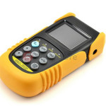
optical power meterAn Optical Power Meter usually knows as Fiber optical power meter is a device that used to measure the absolute optical signal and relate fiber optic loss. The term usually refers to a device for testing average power in fiber optic systems. Fiber optical power meter is a tool for telecommunication and CATV network. Optical power meter consists of a calibrated sensor, measuring amplifier and display. The sensor primarily consists of a photodiode selected for the appropriate range of wavelengths and power levels. On the display unit, the measured optical power and set the wavelength are displayed. Power meters are calibrated using a traceable calibration standard such as a NIST standard.

When to Use Optical Power Meter?
When you install and terminate fiber optic cables, you need to test them. A test should be conducted for each fiber optic cable plant for three main areas: continuity, loss, and power. In order to do this, you’ll need a fiber optic power meter.

How to Use Optical Power Meter?
When you measure fiber optic power with a power meter, you should attach the meter to the cable. Turn on the source of power, and view the meter’s measurement. Compare the meter measurement with the specified correct power for that particular system to make sure it have proper power not too much or too little . Correct power measurement is so important to fiber optic cables because the system works similar to electric circuit voltage, and the power must be just the right amount to work properly.

Classification of Optical Power Meter
There are two types of Optical Power Meter: Ordinary Optical Power Meter and PON Optical Power Meter. Ordinary optical power meter measures the optical power in the fiber link, typically an absolute power value 850/1300/1310/1490/1550/1625nm optical wavelength. While PON Optical Power Meter is more suitable for measuring the fiber to the home (FTTH) networks. Specific measurement: PON Optical Power Meter can send three wavelengths from a single laser output port (1310 nm, 1490 nm, 1550 nm), of which 1310nm can measure upstream transmission direction, 1490 nm and 1550 nm measure downstream direction. Upstream associated with your upload data, downward is download data.

Tips for Selection and Operation

  • Choose the best probe type and interface type.
  • Evaluation of calibration accuracy and manufacturing calibration procedures, and your fiber and connectors to match the required range.
  • Make sure the type and the range of your measurement and display resolution is consistent.
  • With immediate effect db insertion loss measurements.
  • Wear eye protection when working with high-power cables. Even with low-power layouts, it’s wise to check the connectors with your power meter before looking.

The Basic Parameters of Passive Optical Network Devices

Share

There are many devices elementary but necessary for the Passive Optical Network (PON) applications that require the transmission, combining, or distribution of optical signals. These passive devices include the Optical Splitter/Coupler, Optical Switch, Optical Attenuator, Optical Isolator, Optical Amplifier, and WDM Filters (CWDM/DWDM Multiplexer) etc. Tips: The passive devices are components that do not require an external energy source.

When working with these passive devices it is important to have a basic understanding of common parameters. Some of the basic parameters that apply to each device are Optical Fiber Type, Connector Type, Center Wavelength, Bandwidth, Insertion Loss (IL), Excess Loss (EL), Polarization-Dependent Loss (PDL), Return Loss (RL), CrossTalk (XT), Uniformity, Power Handling, and Operating Temperature.

Connector Type and Optical Fiber Type

Many passive devices are available with receptacles or fiber optic pigtails. The pigtails may or may not be terminated with a fiber optic connector. If the device is available with a receptacle or connector, the type of receptacle or connector needs to be specified when ordered. You should also note the type of optical fiber used by the manufacturer of the device to ensure it is compatible with the optical fiber used for your application.

Center Wavelength and Bandwidth

Center Wavelength is the nominal operating wavelength of the passive device.

Bandwidth (or bandpass) is the range of wavelengths over which the manufacturer guarantees the performance of the device. Some manufacturers will list an operating wavelength range instead.

Types of Loss

  • IL is the optical power loss caused by the insertion of a component into the fiber optic system. When working with passive devices, you need to be aware of the IL for the device and the IL for an interconnection. IL as stated by the manufacturer typically takes into account all other losses, including EL and PDL. IL is the most useful parameter when designing a system.
  • EL may or may not be defined by the manufacturer. EL associated with fiber optic couplers, is the amount of light lost in the coupler in excess of the light lost from splitting the signal. In other words, when a coupler splits a signal, the sum of the power at the output ports does not equal the power at the input port; some optical energy is lost in the coupler. EL is the amount of optical energy lost in the coupler. This loss is typically measured at the specified center wavelength for the device.
  • PDL is only a concern for Single-Mode passive devices. It is often the smallest value loss, and it varies as the polarization state of the propagating light wave changes. Manufacturers typically provide a range for PDL or define a not-to-exceed number.
  • RL, short for Return Loss or Reflection Loss, is typically described as this: when a passive device is inserted, some of the optical energy from the source is going to be reflected back toward the source. RL is the negative quotient of the power received divided by the power transmitted.

Tips: IL, EL, PDL, RL are all measured in decibels(dB).

CrossTalk (XT)

XT in an optical device describes the amount of light energy that leaks from one optical conductor to another. XT is not a concern in a device where there is a single input and multiple outputs. However, it is a concern with a device that has multiple inputs and a single output, such as an optical switch. XT is also expressed in dB, where the value defines the difference between the optical power of one conductor and the amount of leakage into another conductor. In an optical switch with a minimum XT of 60 dB, there is a 60 dB difference between the optical power of one conductor and the amount of light that leaked from that conductor into another conductor.

Uniformity

Uniformity is a measure of how evenly optical power is distributed within the device, expressed in dB as well as XT. For example, if a device is splitting an optical signal evenly into four outputs, how much those outputs could vary from one another is defined by uniformity. Uniformity is typically defined over the operating wavelength range for the device.

Power Handing

Power Handling describes the maximum optical power at which the device can operate while meeting all the performance specifications defined by the manufacturer. Power handling may be defined in mW(milliwatt) or dB, where 0 dBm is equal to 1 mW.

Operating Temperature

Operating Temperature describes the range of temperatures that the device is designed to operate in. This can vary significantly between devices, because some devices are only intended for indoor applications while others may be used outdoors or in other harsh environments.

Article Source: http://www.fiberopticshare.com/the-basic-parameters-of-passive-optical-network-devices.html

Huawei Still Maintains Its Leading Position In 2013 Global Broadband Aggregation Equipment Market

Share

1Q13 global DSL, PON and FTTH equipment revenue declined 7% compared with 4Q12, down to $ 1.5 billion; although its global sales of EPON and GPON equipment respectively dropped 5% and 4%, Huawei still maintaining its leader position in global broadband aggregation equipment market (world market share of 33%).

FiberStore news, on June 6th, 2013, Infonetics Research principal analyst Jeff Heynen said, broadband aggregation equipment market got a poor start this year, although the performance of various regions and different technical aspects is different, but the overall revenue began a continuous decline from the first quarter of last year.

“EMEA (Europe, Middle East and Africa) suffered a heavy blow, the region DSL, PON and FTTH equipment sales in this region declined by 27% compared with last quarter, ending the growth of previous three consecutive quarters. The EPON sales in the Chinese market have fallen sharply, but due to China Telecom and China Unicom continuing deploy FTTH GPON-based to provide 20M access services, GPON equipment sales in the region has achieved eight consecutive quarters of growth. Meanwhile, as operators increase investment to resist the competition of DOCSIS 3.0 technology, the North American market contrarian, successfully avoided a quarter of weakness as its previous peculiar”, said Heynen.

The highlights of broadband aggregation equipment market in first quarter of 2013

1Q13 global DSL, PON and FTTH equipment revenue declined 7% compared with 4Q12, down to $ 1.5 billion;

Due to seasonal and Russia, the Middle East carriers initial GPON equipment purchase tide coming to an end, and PON equipment sales in EMEA fell sharply by 50% after achieved double-digit growth in two consecutive quarters;

Despite its global EPON and GPON equipment sales respectively appeared 5% and 4% decline, Huawei maintains its leader position in revenue of global broadband aggregation equipment market (accounting for 33% market share);

Alcatel-Lucent ranked second in global broadband aggregation equipment market, followed by ZTE; ZTE shared China Telecom’s FTTx business by cheap price, its revenue was not that good for several consecutive quarters.