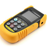
What Is an Optical Power Meter?
 An Optical Power Meter usually knows as Fiber optical power meter is a device that used to measure the absolute optical signal and relate fiber optic loss. The term usually refers to a device for testing average power in fiber optic systems. Fiber optical power meter is a tool for telecommunication and CATV network. Optical power meter consists of a calibrated sensor, measuring amplifier and display. The sensor primarily consists of a photodiode selected for the appropriate range of wavelengths and power levels. On the display unit, the measured optical power and set the wavelength are displayed. Power meters are calibrated using a traceable calibration standard such as a NIST standard.
When to Use Optical Power Meter?
When you install and terminate fiber optic cables, you need to test them. A test should be conducted for each fiber optic cable plant for three main areas: continuity, loss, and power. In order to do this, you’ll need a fiber optic power meter.
How to Use Optical Power Meter?
When you measure fiber optic power with a power meter, you should attach the meter to the cable. Turn on the source of power, and view the meter’s measurement. Compare the meter measurement with the specified correct power for that particular system to make sure it have proper power not too much or too little . Correct power measurement is so important to fiber optic cables because the system works similar to electric circuit voltage, and the power must be just the right amount to work properly.
Classification of Optical Power Meter
There are two types of Optical Power Meter: Ordinary Optical Power Meter and PON Optical Power Meter. Ordinary optical power meter measures the optical power in the fiber link, typically an absolute power value 850/1300/1310/1490/1550/1625nm optical wavelength. While PON Optical Power Meter is more suitable for measuring the fiber to the home (FTTH) networks. Specific measurement: PON Optical Power Meter can send three wavelengths from a single laser output port (1310 nm, 1490 nm, 1550 nm), of which 1310nm can measure upstream transmission direction, 1490 nm and 1550 nm measure downstream direction. Upstream associated with your upload data, downward is download data.
Tips for Selection and Operation
- Choose the best probe type and interface type.
- Evaluation of calibration accuracy and manufacturing calibration procedures, and your fiber and connectors to match the required range.
- Make sure the type and the range of your measurement and display resolution is consistent.
- With immediate effect db insertion loss measurements.
- Wear eye protection when working with high-power cables. Even with low-power layouts, it’s wise to check the connectors with your power meter before looking.
