Maintaining Polarity In Modular Fiber Optic Cassette-Based Cabling

Share

Introduction

Data centers are the central location for data interchange and are found in enterprises, government offices, schools, universities, hospitals, and other networked server farms. The ease of turning nearly any location into an information interchange hub has been enabled by the development of array-based fiber optic cabling systems. Ribbon fiber cables, array-based fiber connectors, and packaged breakout assemblies like fiber optic cassette provides modular small form factor connectivity and enable fast, reliable interconnection of fiber optic links in high-density data center environments.

Once the decision has been made to deploy array-based fiber connectivity, care must be taken to ensure the integrity of connections between the transmitting optical light source and the receiving photo detector. The matching of the transmit signal (Tx) to the receive equipment (Rx) at both ends of the fiber optic link is referred to as polarity. The objective of polarity is simple: provide transmit-to-receive connections across the entire fiber optic system in a consistent, standards-based manner.

Preterminated fiber MTP MPO optical cassettes and loose-tube or ribbon fiber backbone cables are the heart of a modular fiber system. The cassettes and cables typically support groups of full-duplex fiber connections. The challenge for the network system designer becomes one of assuring the proper polarity of these array connections from end to end.

This white paper describes the methods defined in the ratified TIA/EIA (Telecommunications Industry Association/Electronic Industries Association) standard to assure correct polarity using MPO multi-fiber array connectors, cables and cassettes.

Standards and methods:

The TR-42.8 Technical Engineering Subcommittee has developed a standard that addresses the polarity issues associated with multi-fiber array connections. (This document, TIA-568-B.1-7, is available through the Internet for purchase as a reference document.)

Currently, a new release of the TIA-568 Commercial Building Cabling Standard is under development as the TIA-568-C series of standards. The fiber-systems section of this series will be TIA-568-C.1, and will include information on array system polarity along with a description of MPO array cables, duplex patch cords, and array transitions.

Modular fiber optic cassettes:

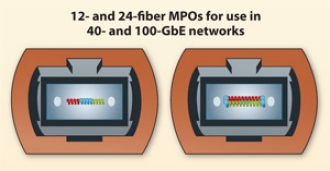
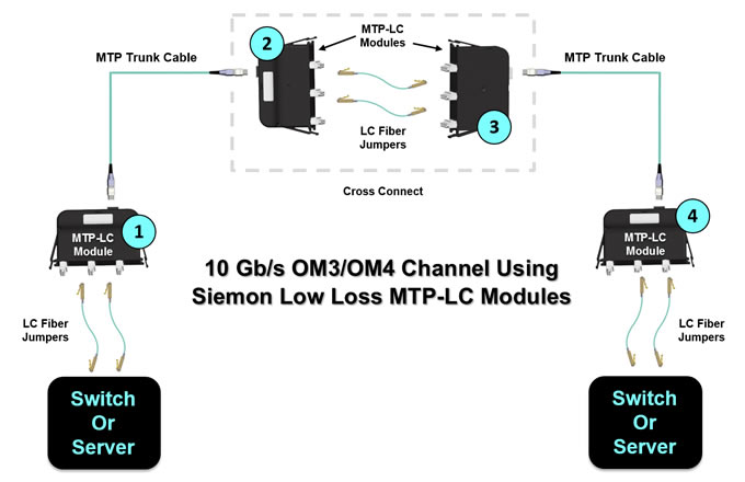
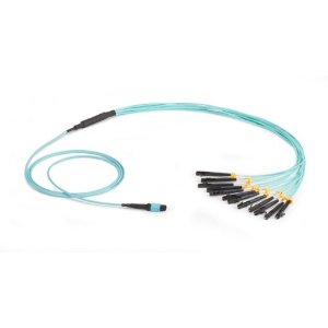
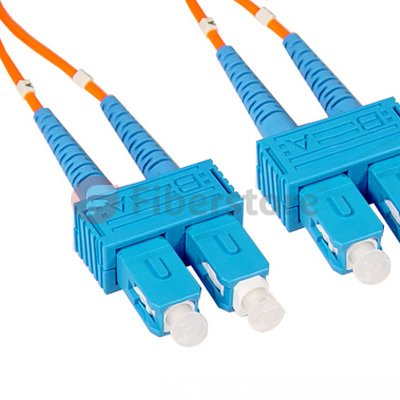
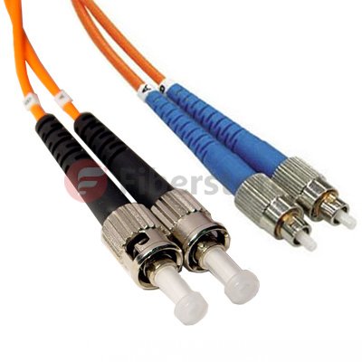
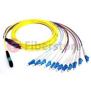
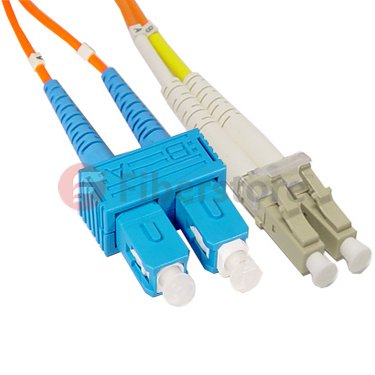
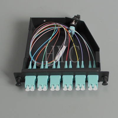
Modular fiber optic cassettes-enclosed units containing 12- or 24-fiber factory-terminated fanouts-serve to transition small-diameter ribbon cables terminated with an MPO connector to the more-common LC or SC interfaces used on the transceiver terminal equipment. The fanouts typically incorporate SC, LC, ST-style or MT-RJ connectors plugged into adapters on the cassette’s front, and an MPO connector plugged into an MPO adapter on the cassette’s rear side.

One or more MPO fanout assemblies may be installed inside the fiber optic cassette to connect up to two, 12-fiber ribbon cables, for a total of 24 fibers. Alignment pins that are preinstalled in the MPO connector within the cassette precisely align the mating fibers in the MPO conn

ectors at either end of the array cables that plug into the cassettes.

MPO Cassette

The transition that takes place inside a fiber optic cassette, the connector keying for the cassette and the corresponding MPO array cables are all thoroughly defined for all three connectivity methods listed in the TIA standard. A common transition, factory-installed inside a cassette, is used for all three methods. The adapter mounted at the rear of a cassette defines it as either a Method A or Method B type. The only difference between the two cassette types is the orientation of the internal MPO connector with respect to the mating MPO array cable connector.

Method A cassettes make a “key up”-to-“key down” connection between the internal MPO connector and the MPO array cable connector. Method B cassettes make a “key up”-to-“key up” connection. It is important to note that a Method B cassette will not allow single mode angle-polish mated-pair connection because the angles of the mating connectors are not complementary. This prevents a Method B cassette or adapter from being used in single mode applications that require low return losses-a significant limitation.
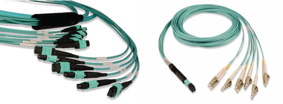
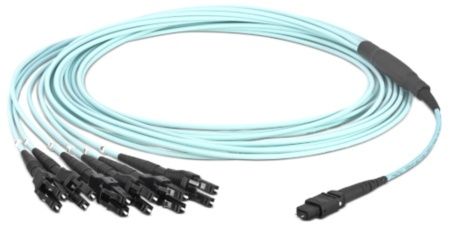
MPO array cables:

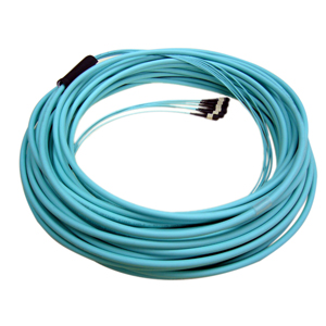
Modular fiber optic cassettes are connected to one another with MPO to MPO ribbon backbone cables. The connectors on these cables do not contain alignment pins, but they do have mating alignment holes. Alignment pins are factory-installed in the MPO fanout connectors installed inside the fiber optic cassette.

MTP MPO fiber cables

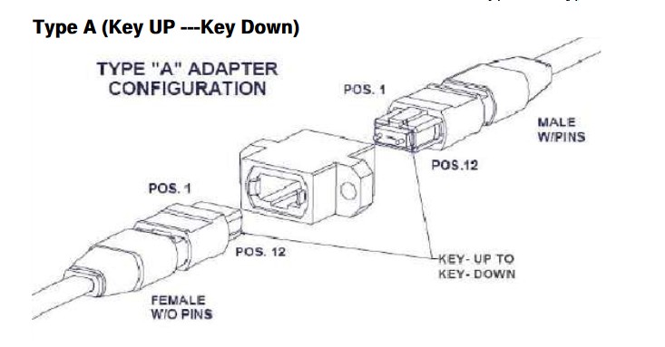
The TIA standard defines three different 12-fiber MPO cable: Types A, B, and C. Each is used for its respective connectivity method (Methods A, B, and C).

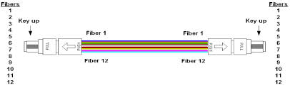
For the Type, A array cable, the opposing connections at each end of the cable have the same fiber positions, except that one end has the key oriented facing up while the other end has the key oriented facing down.

MPO to MPO

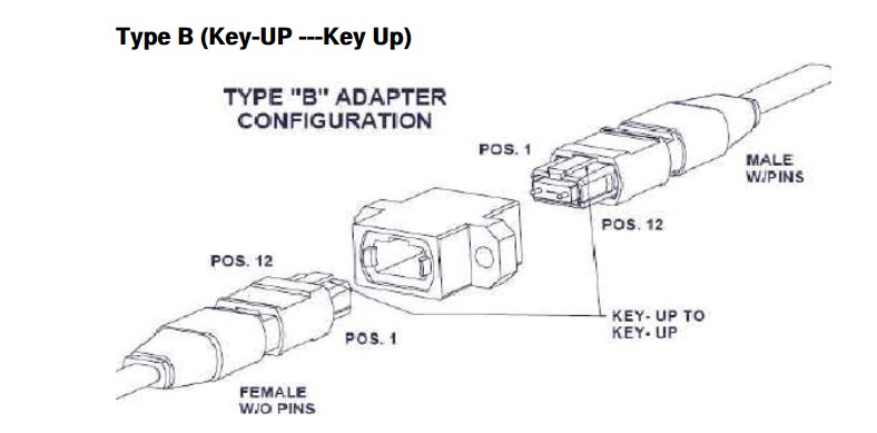
The Type B array cable has opposing connectors with both keys oriented facing up, but the fiber positions are reversed at each end; the fiber at position 1 at one end is connected to position 12 in the connector at the opposing end.

MPO to MPO Fiber

In the Type C array cable, the key is facing up at one end and facing down at the other end. It looks like a Type-A array cable, but the Type-C cable is designed such that adjacent pairs of fibers are crossed from one end to the other. In this case, the fiber at position 1 on one end of the cable is shifted to position 2 at the other end of the cable. The fiber at position 2 on one end is shifted to position 1 at the opposite end, and so on.

Connectivity methods:

The fiber patch cord, cassette (transition) and array cable previously described are used in specific combinations to form end-to-end full-duplex fiber links. Each component of the total fiber cabling system is unique, underscoring the importance of assuring that the correct component is selected and used in the proper sequence.

Importantly, regardless of which method defined in the TIA standard you use, there must be a pair-wise flipping (A-to-B polarity swap) that takes place at some point in the link. If the pair-wise flipping does not occur in the cassette (transition), then the pair-wise flipping must occur in the duplex patch cord, or in the MPO-to-MPO array cables and/or adapters.

Conclusions:

Modular fiber optic cassette-based cabling technology offers many advantages facilitating high-performance, rapid, and error-free installation, as well as reliable, robust operation. The best way to maintain correct optical polarity in these systems is to select a standards-based approach and to adhere to it throughout an installation. The three connectivity methods defined in the TIA/EIA-56-B.1-7 standard present the guidelines for maintaining polarity using array connections.

It is in the best interest of the installer and end-user to select modular fiber optic cassette-based solutions that adhere to TIA standards. Proprietary non-standards-based solutions will not assure interoperability. In addition, those solutions may not be compatible with commercially based components designed to meet the TIA standards. Selecting modular fiber systems that comply with TIA standards can help to prevent costly troubleshooting and rework of the installed fiber cable plant. Additionally, fiber-network installers can be assured of a readily available product supply from multiple stocking supply sources with acceptable delivery lead times.

MTP/MPO System Solutions – High Density Connectivity in the Data Center

Share

MPO/MTP system solutions are steadi-ly gaining in significance. Data centers in particular have a great need for compact and flexible plug-and-play systems that are pre-measured and preterminated at the factory. MPO/MTP system solutions allow users to achieve complete end-to-end cabling in keeping with the new standard for data centers. In the IEEE 802.3 standard, 40 Gb/s and 100Gb/s were defined with MPO connector technology. The crucial factor is the insertion loss and return loss of the components. Controlled production processes and ultra-precise end-face geometry are needed to satisfy these tough requirements. With the MPO/MTP multi-fiber system, a data center is well-equipped for future transmission rates of 40 and 100Gb/s.

Benefits of deploying modular, high-density optical solutions, such as MPO-based connectivity (including MPO trunk assemblies, breakout modules and breakout harnesses) in a structured wiring architecture include 50% cable-tray space savings, 80% improvement in deployment time, and 70% bulk-cable reduction in cabinets and racks. A modular, high-density solution deployed in a structured wiring topology can easily scale to hundreds of thousands of ports and significantly reduce the time to conduct MACs in the data center, thus reducing operational costs.

So now, we have the means to cope with future growth and churn in the data center. Now, let’s address the issue of keeping this modular high-density structured cabling system in place to handle future higher-data-rate applications.

In addition to manageability and scalability, a benefit to deploying a modular, high-density MPO-based cabling system is the available migration path to increased data rates. With some consideration of performance specifications, the infrastructure can easily migrate to future higher-data-rate technologies, such as parallel optics, which will be used in 32-, 64-, and 128-Gigabit Fibre Channel; and 40- and 100-Gigabit Ethernet. In fact, by deploying an optical cabling system that meets InfiniBand 12X-QDR (120-Gbit) cable skew performance requirements of = 0.75 ns and distance specifications, the same infrastructure that is carrying serial transmission today can be easily migrated to transmit parallel-optic InfiniBand signals.

To mitigate this issue and increase the lifecycle of an optical-cabling infrastructure, deploy high-quality low-loss optical components. Low-loss MPO trunks, breakout harnesses, modules and jumpers minimize channel insertion loss and enable the cabling infrastructure to easily migrate to future higher data rates.

For example, 8-Gbit Fibre Channel will support a distance of 100 meters using OM3 fiber and a connector budget no greater than 2.4 dB. If an MPO mated pair has a maximum insertion loss of 0.5 dB, and each MTP-to-LC breakout module wasspecified at a maximum insertion loss of 0.75 dB, then theresulting maximum connector loss in the channel will be 2.75 dB.

This exceeds the recommended maximum 2.4 dB connector loss budget of 8-Gbit Fibre Channel at 100 meters, thereby reducing the supportable distance at 8-Gbit Fibre Channel; however, if low-loss components were specified into the same cable plant at 0.5-dB maximum insertion loss per MTP-to-LC breakout module and 0.35-dB maximum per MTP mated pair, then the resulting maximum connector loss in the channel will be 1.85 dB, providing support of 8-Gbit Fibre Channel beyond 100 meters.

As previously discussed, TIA-942 addresses the use of ZDAs as part of the recommended topology for datacenters. Implementing a distributed zone solution reduces pathway congestion and facilitates the implementationof MACs common in the data center environment. Implementing a zone topology can increase the number of connection points in a given channel. Using components with low-loss performance enables zone connectivity without sacrificing distance capabilities due to channel insertion loss.

MPO Fiber

Additional methods to implement zone distribution with reduced channel insertion loss include using components that are optimized for the architecture. Solutions that offer a combined MPO-based trunk assembly and breakout module can eliminate connector pairs while still offering the flexibility of zone cabling, thereby reducing total channel insertion loss. Now we introduce some MTP/MPO assemblies when you are solving MTP/MPO system.

MTP high density cabling solutions utilizes MPO (multi fiber push on) ferrule providing connection of 12 or 24 fibers. MTP provides superior physical and optical characteristics than standard MPO for precision alignment with spring loaded mechanism and guide pins. They have a removable adaptor that mates female connectors to a male connector with specially designed guide pins for orientation and maintaining polarity along the channel. The Micro-core cables used in factory terminated MTP fiber cable assemblies give 65% reduction in cable size from traditional fiber cables. Pre-connected MTP solution with 24 core LC duplex adapters offers 72 LC terminations in 1U rack space and 288 LC terminations in 4U rack space using modular patch panels.

MTP Patch Panels are scalable modular which are designed for high density Gigabit Ethernet Applications.They are used for terminating backbone cables at the Main Distribution Area (MDA) and Horizontal Distribution Area (HDA). MTP Patch Panels are available with 1U and 4U, suitable for standard 19” racks. 1U MTP Patch Panel can accommodate up to three MTP Cassettes, giving a high connectivity of 72 LC fiber terminations in it. 4U MTP Patch Panel can accommodate up to 12 MTP Cassettes, resulting in a maximum of 288 LC terminations per panel.

Fiberstore offer a wide range of MTP/MPO product including MTP and MPO trunk cables, MPO and MTP cassettes, MTP and MPO harness (breakout) cables. MTP/MPO Cable assemblies are fully compliant with IEC Standard 61754-7 and TIA 604-5. All MTP and MPO assemblies can be customize. More details, please call us or send an email to our customer services.

24-Fiber MPO 10/40/100 Gigabit Ethernet Interconnect

Share

In 2002, the IEEE ratified the 802.3ae standard for 10 GbE over fiber using duplex fiber links and vertical cavity surface emitting laser (VCSEL) transceivers. Most 10 GbE applications use duplex LC style connectors where one fiber transmits and the other receives. Standards efforts aimed at finding a cost-effective method to support next-generation speeds of 40 and 100 Gbps, and in 2010, the IEEE ratified the 802.3ba standard for 40 and 100 GbE. Similar to how transportation highways are scaled to support increased traffic with multiple lanes at the same speed, the 40 and 100 GbE standards use parallel optics, or multiple lanes of fiber transmitting at the same speed. Running 40 GbE requires 8 fibers, with 4 fibers each transmitting at 10 Gbps and 4 fibers each receiving at 10 Gbps. Running 100 GbE requires a total of 20 fibers, with 10 transmitting at 10 Gbps and 10 receiving at 10 Gbps. Both scenarios call for using high-density multi-fiber MPO style connectors.

MPO

For 40 GbE, a 12-fiber MPO connector is used. Because only 8 optical fibers are required, typical 40 GbE applications use only the 4 left and 4 right optical fibers of the 12-fiber MPO connector, while the inner 4 optical fibers are left unused as shown in Figure 1.

12-fibers

To run 100 GbE, two 12-fiber MPO connectors can be used one transmitting 10 Gbps on 10 fibers and the other receiving 10 Gbps on 10 fibers. However, the recommended method for 100 GbE is to use a 24-fiber MPO style connector with the 20 fibers in the middle of the connector transmitting and receiving at 10 Gbps and the 2 top and bottom fibers on the left and right unused as shown in Figure 2.

Knowing that 40 and 100 GbE are just around the corner,and already a reality for some, many data center managers are striving to determine which physical layer solution will support 10 GbE today while providing the best, most effective migration path to 40 and 100 GbE. While many solutions on the market recommend the use of 12-fiber multimode trunk cables between core switches and the equipment distribution area in the data center, TE Connectivity recommends and offers a better standards-based migration path with the use of 24-fiber trunk cables.

The use of 24 fiber trunk cable between switch panels and equipment is a common-sense approach. In this scenario,24-fiber trunk cables with 24-fiber MPOs on both ends are used to connect from the back of the switch panel to the equipment distribution area. For 10 GbE applications, each of the 24 fibers can be used to transmit 10 Gbps, for a total of 12 links. For 40 GbE applications, which requires 8 fibers (4 transmitting and 4 receiving), a 24-fiber trunk cable provides a total of three 40 GbE links. For 100 GbE, which requires 20 fibers (10 transmitting and 10 receiving), a 24-fiber trunk cable provides a single 100 GbE link. Why is this more advantageous than using 12-fiber trunk cables? It all comes down to a better return on investment and reduced future operating and capital expense.

As mentioned previously, 40 GbE uses eight fibers of a 12-fiber MPO connector, leaving four fibers unused. When using a 12-fiber trunk cable, those same four fibers are unused. For example, three 40 GbE links using three separate 12-fiber trunk cables would result in a total of 12 unused fibers, or four fibers unused for each trunk.

With the use of 24-fiber trunk cables, data center managers actually get to use all the fiber and leverage their complete investment. Running three 40 GbE links over a single 24-fiber trunk cable uses all 24 fibers of the trunk cable. This recoups 33% of the fibers that would be lost with 12-fiber trunk cables, providing a much better return on investment. At 100 GbE which requires 20 fibers, a total of four fibers are left unused when using either two 12-fiber trunk cables or when using a single 24-fiber trunk cable. However, additional benefits come into play for 100 GbE and 12-fiber trunk cables are not the recommended configuration for 100 GbE. Figure 3 shows the ratio of 24-fiber trunk cables to corresponding connector types for each application.

The 10 Gigabit Interconnect Solution, like all of the planned migration designs, employs a 24-fiber optical trunk with a single MPO-type connector at each end. A trunk interfaces with the rear of a 24-fiber MPO cassette that breaks out the trunk fibers into twelve duplex LC connections at the front, supporting 24 fibers per cassette. This cassette resides in a time-proven RMG chassis which provides cable management and protection for both the MPOs at the rear and LC cords at the front. Fiberstore enclosures are stackable and available in 1, 2, and 4 RU versions and support up to 36 duplex LCs (72 fibers) per rack unit. They can be populated all at once, or added to or upgraded a cassette at a time in the future. The Fiberstore enclosure also supports high density 10 Gigabit cassettes, as well as 40 and 100 GbE versions, allowing an upgrade path by changing the cassette at the front and using existing and additional 24-fiber trunks at the rear.

High Density 10 Gigabit Fiber Cassettes also utilize 24-fiber MPO trunks and support connection from 40 Gigabit switch ports that have been remotely enabled as four 10 Gigabit independent paths. MPO based QSFP ports at the switch interface with a cassette at one end of the trunk, and a break-out cassette divides these signals into duplex LC pairs at the other end. MPO cassettes have two 24-fiber MPO connectors at the rear and six 8-fiber MPOs at the front. Each cassette supports distribution of six 40 Gigabit Ethernet paths, each containing four duplex 10 Gigabit links. These cassettes are connected via standard 24-fiber MPO trunks to a pair of two 2×12 LC duplex cassettes at the other end of the trunk. This pair of cassettes maintains fiber paths and polarity and provides proper fiber mapping from transmit at one end to receive at the other over a total of twenty-four 10 Gigabit paths.

Fiberstore supply 12, 24, 48, 72, 96 and 144 fiber core constructions with OM1, OM2, OM3 or OM4 fiber trunk cable, these trunk cable assemblies are composed of high quality LSZH jacketed fiber optic cables, connecting equipment in racks to MTP/MPO backbone cables. All kinds of MTP MPO cable length can be customized, meanwhile we also provide 40G/100G MTP/MPO cable solution.

Fiber Transmissions at Higher-speed Ethernet

Share

When moving to 40/100GbE, the most important difference in backbone and horizontal multimode applications is the number of fiber strands. 40GBASE-SR4 uses 4 strands to transmit and receive for a total of 8 strands. 100GBASE-SR10 uses 10 lanes to transmit and receive for a total of 20 strands. SMF remains a 2-strand application and although the fiber is less expensive, SMF optics and electronics can be 10x more expensive. In data centers and backbones, it may be possible to have 8 or 20 individual strands of fiber. However, those strands may take disparate paths from one end to the other and this can cause delay skew (known as bit skew) resulting in bit errors. For this reason, the 40/100GbE standards are written around fiber optic trunk assemblies that utilize a MPO or MTP multi-fiber array connector. In these assemblies, all strands are the same length. Also referred to as “parallel optics,” this construction minimizes bit/delay skew, allowing the receive modules to receive each fibers information at virtually the same time.

MPO (Multi-fiber push-on) and MTP (Mechanical Transfer Push-on) are available in both 12 and 24 strand termination configurations used at the end of a trunk assembly. The MTP design is an improved version of the MPO. The patented MTP connector is a ruggedized version with elliptical shaped, stainless steel alignment pin tips to improve insertion guidance and reduce guide hole wear. The MTP connector also provides a ferrule float to improve mechanical performance by maintaining physical contact while under an applied load. MPO MTP trunks also support for the 10GBASE-SR/SX applications although only two fiber strands are used. In this case trunks are connected to cassettes and/or hydra assemblies, which break out the multiple fibers into two-strand connections (typically LC or SC).

MPO Cabling

The second difference in high-speed fiber configurations is polarity. For 2-strand applications such as 10GbE transmission, managing polarity is as simple as reversing the strands somewhere over the channel. This is true if the channel is constructed of individual strands or is part of a trunk assembly. In trunk assemblies, which have historically been 12-strand, there are three suggested polarity methods in the standards (as shown in the following table).

As shown above, 2-strand application polarity managing is relatively easy. When migrating from 2-strand to multi-strand parallel optics, it is important to note which polarity method was selected to assure that the correct assemblies are purchased for higher speeds. All polarity methods can be converted from 2-strand to 12-strand applications.

40G

It is important to note that these polarity methods are suggested in the standards, not mandated. However, the mandate does state that a polarity method should be established and maintained throughout all fiber channels, mapping the transmit strand from one end to the receive strand at the other. This does not change for higher fiber count transmissions, with the exception that more strands are involved. To better visualize the transmission for multistrand applications, consider the following diagrams:

40GBASE-SR uses 8 strands of a 12-strand MPO/MTP trunk cable, (4 to transmit and 4 to receive). The middle 4 strands in the MPO/MTP connector remain dark. The interface on equipment will accept an MPO/MTP array connector rather than a traditional LC.

100GbE has three approved methods for transmission including one 24-strand (shown left) or two 12-strand trunks either “over and under” or “side-by-side” (shown right- Side-by-side configuration is not shown). The transmission uses 10 strands to transmit and 10 to receive leaving the outer unused strands dark. It is also possible to connect two 1- strand trunks via a “Y” assembly that converts two 12-strand trunk assemblies to one 24-strand assembly. Polarity must also be considered regardless of the method chosen and supported by the electronics.

The new MTP cables can bridge legacy 1Gbps/10Gbps networks over to 40Gbps/100Gbps networks, and can act as the trunk line on a network backbone. Since a single fiber cable can connect up to 24 devices, fewer cables are needed, cutting down on installation labor. The high-density, small form factor also saves space and improves air flow. With its push-pull release mechanism, the MTP connector is easy to engage and disengage.

FiberStore provide a wide range of MTP/MPO products including single mode or multimode MPO and MTP fiber cable. High density MTP/MPO trunk cables with up to 144 fibers in a single cable. Fiberstore also offer wide range of MTP MPO cassette. The standard cassettes can accommodate 12 and 24 port configurations. Different sizes of cassettes are available. Available in all fibermodes and connector options. Custom Options available including MPO MTP taps and MTP/MPO Silitter combinations.

Low-loss Connectivity For Multimode Fiber Applications

Share

Optical insertion loss budgets are now one of the top concerns among data center managers, especially in today’s large virtualized server environments with longer-distance 40 and 100 gigabit Ethernet (GbE) backbone switch-to-switch deployments for networking and storage area networks (SANs). In fact, loss budgets need to be carefully considered during the early design stages of any data center—staying within the loss budget is essential for ensuring that optical data signals can properly transmit from one switch to another without high bit error rates and performance degradation.

low-loss-multifiber-connectivity

With the length and type of the fiber optic cable and number of connectors and splices all contributing to the link loss, data center managers are faced with the challenge of calculating each connection point and segment within their fiber channels. Multi-fiber push on (MPO) or mechanical transfer push on (MTP) connectors are rapidly becoming the norm for switch-to-switch connections due to their preterminated plug and play benefits and ease of scalability from 10 to 40 and 100 gigabit speeds. Unfortunately, typical MPO MTP module insertion loss may not allow for having more than two mated connections in a fiber channel, which significantly limits design flexibility and data center management. Low loss, rather than standard loss, MPO/MTP connectors better support multiple mated connections for flexibility over a wide range of distances and configurations while remaining within the loss budget.

MTP LC

Typical MPO/MTP connectors, which are required for 40 and 100 GbE eployments have insertion loss values that range from 0.3 dB to 0.5 dB. Typical LC multimode fiber connectors have loss values that range from 0.3 dB to 0.5 dB. While better than the allowed 0.75 dB TIA value, typical connector loss still limits how many connections can be deployed in 10, 40 and 100 GbE channels. For example, with an LC connector loss of 0.5 dB, a 300-meter 10 GbE channel over OM3 fiber can include only three connectors with no headroom. Having just two or three connections prevents the use of cross connects at both interconnection (MDA) and access switches (HDA).

Due to improvements in connector technology and manufacturing techniques, Fiberstore has succeeded in lowering the loss to 0.20 dB for MTP connectors and to 0.15 dB (0.1 dB typical) for LC and SC connectors, well below the industry standard of 0.75 dB and loss values offered by other manufacturers.

For 10 GbE, Fiberstore low loss LC fiber jumpers offer a loss of 0.15 dB (typical 0.1 dB) and Fiberstore low loss plug and play MTP to LC or SC modules offer a loss of 0.35 dB (typical 0.25 dB). For 40 and 100 GbE, MTP to MTP pass-through adapter plates and MTP fiber jumpers offer a loss of 0.2 dB. These lower loss values allow data center managers to deploy more connection points in fiber channels, enabling the use of distribution points or cross connects that significantly increase flexible configuration options.

Table 2 below provides an example of how many connections can be deployed in 10, 40 and 100 GbE channels over OM3 and OM4 multimode fiber using low loss MTP to LC modules for 10 GbE and low loss MTP to MTP pass-through adapters for 40 and 100 GbE versus standard loss solutions.

As indicated in Table 2, the use of low loss connectivity allows for four connections in a 10 GbE OM3 or OM4 channel compared to just two when using standard loss connectivity. Low loss connectivity allows for eight connections in a 100- meter 40/100 GbE channel over OM3 versus just four connections using standard loss, and five connections in a 150-meter 40/100 GbE channel over OM4 fiber compared to just two connections using standard loss. Deploying cross connects between interconnection and access switches requires a minimum of four connections, depending on the configuration. Therefore, cross connects in a full-distance optical channel are simply not feasible without low loss connectivity.

Figures 6, 7 and 8 shows some example scenarios for deploying cross connects in 10 GbE and 40/100 GbE channels over OM3 and OM4 fiber using Fiberstore low loss fiber connectivity. In Figure 6, all changes are made at the cross connect with LC fiber jumpers. The switches remain separate and the permanent MTP trunk fiber cables need only be installed once. The cross connect can be placed anywhere within the channel to maximize ease of deployment and manageability.

MTP Trunk Cable

Figure 7. shows an OM3 40/100 GbE channel with six Fiberstore low loss MTP-MTP pass-through adapter plates and low loss trunks. This scenario offers 0.4 dB of headroom and provides even better manageability and security. All changes are made at the cross connects via MTP fiber jumpers, switches remain separate, and the MTP trunk cables need only be installed once.Once again, the cross connects can be located anywhere in the data center for maximum flexibility. This allows for one-time deployment of high fiber-count cabling from the cross connect at the interconnection switch to the cross connect at the access switch. Adding additional access switches can be accomplished with short fiber runs from the cross connect.

Figure 7: For maximum flexibility, manageability and security, up to eight low loss MTP-MTP pass-through adapters can be deployed using low loss trunks in a 100-meter 40/100 GbE switch-to-switch backbone channel over OM3 fiber.

If the loss budget does not permit deploying six MTP to MTP adapters, one option is to deploy MTP to LC or MTP to MTP jumpers from the cross connect to the equipment, depending on the equipment interface. For example, if using OM4 fiber to extend the channel distance to 150 meters, up to five Low Loss MTP-MTP pass through adapters can be deployed as shown in Figure 8.

Signal Crossover in Fiber Optic Systems With MPO Cables

Share

Ribbon cables terminated with MPO connetors present some challenges when it comes to maintaining the correct signal crosssover in a segment consisting of multipe fiber optic srands. The ANSI/TIA-568-C.3 standard provies a set of “Guidelines for Maintaing Polarity Using Array Connetors” that decribe three types of MPO-to-MPO array cables, defined as Types A, B, and C. These cables are used to provide three different methods for maintaining a crossover connection. Method A is prefferred method, and is based on Type A MPO Fiber cables.

Figure 17-6 shows a Type A straight through ribbon cable with 12 fibers terminated in MPO connetor. A Method A backbone link is cabled “straight through”, terminating in the cabling system patch panel. One end of the link will have a straight through patch cable, connetion from the patch panel to the Ethernet interface. The other end of the link will have a crossover cable connecting to the Ethernet interface. The guidelines recommend keeping all of the crossover patch cables at one end of the link, to keep the system as simple as possible and help the installer to avoid connecting the wrong type of patch cale.

MPO Fiber

The guidelines also show Method B and Method C, which are two methods for providing a crossover patch built into the MPO backbone cables themselves. Given the complexity of these approaches and the difficulty of implementing them correctly, they are both rarely used.

As you can see, there are a variety of approaches to managing the signal crossover for the 12-fiber and 24-fiber systems needed to support 40 and 100 Gb/s Ethernet. For the best results, make sure you know which method your site is using in the cabling system, and order the correct MPO cable types to make the connections and achieve the signal crossover. Note that some vendors provide special MPO connectors that make it possible to change connector gender and polarity(crossover) in the field, which coulde be a handy way to resolve MPO-to-MPO connectivity issues.

To provide an introduction and basic information to readers, this section begins with a presentation of the components needed for a parallel optical MPO connection.

MPO connectors contact up to 24 fibers in a single connection. A connection must be stable and its ends correctly aligned. These aspects are essential for achieving the required transmission parameters. A defec-tive connection may even damage components and or cause the link to fail altogether.

MPO cables are delivered already terminated. This approach requires greater care in planning in advance but has a number of advantages: shorter installation times, tested and guaranteed quality and greater reli-ability.

Fiber trunk cables serve as a permanent link connecting the MPO modules to each other. Trunk cables are available with 12, 24, 48 and 72 fibers. Their ends are terminated with the customer’s choice of 12-fiber or 24-fiber MPO connectors.

trunk fiber optic cables

Harness cables provide a transition from multi-fiber cables to individual fibers or duplex connectors.The 12-fiber harness cables available from R&M are terminated with male or female connectors on the MPO side, the whips are available with LC or SC connectors.

Harness cable

Fiberstore supply MTP MPO fiber cables, MTP Cassette and MPO Cassette.  MTP MPO cables are available in 4,8,12, 24, and 48 fiber array configurations.  Many additional options and combinations are available. All fiber optic cables are customizable.

International Wire And MTP MPO Cable Symposium

Share

Harnesses are custom-engineered to allow seamless integration into various Storage Area Network (SAN) directors. Harnesses are used to transition the 12-fiber MPO connectors into LC connectors. A pinned MPO connector on one end connects to a trunk through a connector panel in the housing, while the other end is equipped with six LC-style uniboot connectors, which plug into optoelectronic ports.

As with jumpers, bend-insensitive fiber reduces the cable diameter and allows for the uniboot design described above. Additionally, the new fiber allows for an innovative new design of the harness furcation, resulting in the overall length reduction of the furcation. The bend-insensitive fiber also eliminates the need for bend radius control components at both the front and rear of the furcation such as segmented boots, heat shrink,spiral wraps and other such support. Likewise, this allows for precision staggering of the harness legs without using the above-mentioned radius control components. MPO connector leg slack can be stored in the vertical manager without fear of inducing macrobend attenuation loss. Figure 21 shows an engineered uniboot harness, Figure 22 shows the harness installed in the equipment rack, and Figure 23 shows the harness connected to a 48-port blade server.

The use of harnesses provides an innovative solution that occupies less space than traditional jumpers as the cable end of the harness is much smaller than the 12 equivalent patch cords. This reduced cabling bulk improves airflow for increased cooling and facilitates easier moves, adds and changes (MACs).

In typical data center applications, trunk cable branch into 12-fiber legs at a furcation plug that provides cable demarcation and strain relief. Each leg is equipped with an MPO connector, which is a 12-fiber push/pull optical connector with a footprint similar to the SC simplex connector. These high-density connectors are used to significantly accelerate the network installation process, minimize errors and reduce space. Trunks in data center applications utilizing MPO connectors typically support 12 to 144 fibers. Figure 24 shows a 144-fiber trunk cable assembly with a pulling grip on one end for ease of installation.

Through the use of bend-insensitive fibers in micro-module cable designs, trunk cables are on average 30 percent smaller in outer diameter. In addition, the minimum bend radius is now five timesthe outer diameter of the cable compared to 10 times the diameter in traditional trunks. Smaller-diameter trunks allow for more than 50 percent more cables to be stored in cable trays, while minimizing cable tray weight and impediments to cooling air.The smaller bend radius allows for extra cable slack to be stored without interfering with cable routing or causing attenuation that may adversely impact system performance.

Plug & Play Universal Systems utilize the MTP® Connector. The MTP Connector is a multi-fiber array-style connector that can accommodate up to 12 fibers in roughly
the same size and footprint as an SC connector. It has a single high-density footprint of 25 x 10 mm and features simple push-on/pull-off mating. A general industry term for this style of connector is MPO. This connector, which is used in both multimode and single-mode applications,maximizes valuable panel and hardware space, ensuring high density. MTP Connectors are manufactured with either alignment pins or with alignment holes to ensure proper alignment of the fibers. A connector with alignment pins always mates with a connector with alignment holes. (Figure 7.1). The MTP Connector offers:

• Up to 54 percent reduction in pathway congestion
• Modularity and scalability with a fiber count that maps to current and future line-card port counts
• Universal wiring and superior loss performance for migration to higher data rates

A traditional Plug & Play Universal Systems trunk consists of an optical cable with each end factory-terminated with MTP Connectors and a pulling grip on one or both ends.Trunks are available in a variety of fiber types and typically carry a plenum rating unless otherwise specified. When ordering Plug & Play Universal Systems trunks, the MTP Connectors on both ends will have pin alignment holes. This ensures that it will integrate with the remaining parts of the system that have pins. It should be noted that MTP Connector panels have neither pins nor alignment holes, as they are connection points for various components of the Plug & Play Universal Systems.

To successfully deploy a cable that is preterminated on both ends, it is necessary to accurately predetermine the installed link length. This can be relatively straightforward if welldefined pathways and spaces exist for the cable route, which is usually true for the data center environment. If the route is less defined, preterminated cables can still be utilized by specifying the trunk cables be longer than the known length and planning for the storage of excess cable loops.

Fiber Patch Cord Power Loss Measurement

Share

Multi-mode patch cord optical loss power measurement is performed using the steps described in ANSI/TIA-526-14,method A. The patch cord is substituted for the cable plant. Because patch cords are typically no longer than 5 m, the loss for the optical fiber is negligible and testing can be performed at 850 nm or 1300 nm. The loss measured in this test is the loss for the patch cord connector pair. ANSI/TIA-568-C.3 states that the maximum loss for a connector pair is 0.75 db.

After setting up the test equipment as described in ANSI/TIA-526-14, method A, clean and inspect the connectors at the ends of the fiber patch cord to be tested. Verify that your test jumpers have the same optical fiber type and connectors as the patch cords you are going to test. The ANSI/TIA-526-14 being used for testing. Ensure that there are no sharp bends in the test jumpers or patch cords during testing.

Because both patch cord connectors are easily accessible, optical power loss should be measured in both directions. The loss for the patch cord is the average of the two measurements. If the loss for the patch cord exceeds 0.75dB in either direction, the patch cord needs to be repaired or replaced.

Connector insertion loss measurement isolates the loss of a single connector on a cable assembly. It may be referred to as connector loss. Many time cable assemblies are shipped from the manufacturer with the insertion loss for each connector listed on the packaging. The package shown in Figure 33.37 contains a duplex multi-mode patch cord. In the upper-left corner of the package, a label lists the insertion loss measurements for each connector.

Connector test jumper 1 as shown earlier in Figure 33.31. Record the optical power displayed by the optical power meter. This number is the reference power measurement. This number is typically around -20dBm with a 62.5/125μm multimode optical fiber and -23.5dBm with a 50/125μm multimode optical fiber. These numbers can vary from OLTS to OLTS. The following are 62.5/125μm and 50/125μm multimode fiber from fiberstore, picture is below:

SC-SC Multi mode

SC-SC Plenum Duplex 62.5/125 Multi-mode Fiber Patch Cable, with SC to SC termination, this fiber optic patch cable is specificially designed for ethernet, multimedia, or communication applications. The SC connector features a push-pull locking system. The plenum rating provides the fire protection required to run this cable within walls and air plenums without using conduit. The patented injection molding process provides each connection greater durability in resisting pulls, strains and impacts from cabling installs.

FC-ST

ST Fiber Cable connector has a bayonet-style housing and a long spring-loaded ferrule hold the fiber. They are available in both multi-mode or single mode versions. Horizontally mounted simplex and duplex adapters are available with metal or plastic housing.

MTP MPO Cable Assemblies

Share

MTP/MPO assemblies utilize a push-pull connector housing for a quick and reliable connection. For optical device interconnections, MTP MPO assemblies interface on the daughter card to HBMT and BMTP adapters on the backplane.

Multiple transitions fibers are available to meet a variety of fiber routing requirements.Fanouts to single fiber leads connectorized with Molex industry standard LC, MU, FC, SC and ST connectors are available to interconnect with the current installed base of transmitters, receivers and patch panels.

A singlemode low loss version of the MTP/MPO connector is achieved by using more precise MT 8-fiber ferrules and guide pins. The superior precision of the singlemode low loss MT ferrule yields comparable insertion loss values of the single fiber ceramic ferrules.

Our fiberstore offers a wide range of high quality MTP/MPO Patch Cable, MTP/MPO harness cable, MTP/MPO trunk cable,ect. The following are some products related MTP/MPO products.

MTP Trunk Cable

MTP Fiber Trunk Cables for Point to Point Fiber Optic Cabling – 12, 24, 36, 48, 72, 144 Count Fibers per Trunk.

MTP trunks are bundles of 1, 2, 3, 4, 5 or 6 individual MTP Cables and have 12, 24, 36, 48, 72, 144 Count Fibers per Trunk, respectively. We manufacture and supply MTP trunks in a large diversity of lengths and environmental standards from data center networking to industrial applications.

MPO Fiber

These MPO Fiber connector come with a push and pull latching technology are available with a range of 4, 8, 12, or 24 fibers. Housings are color coded to distinguish green for single-mode and beige for multi-mode. Engineered in compliance to IEC Standards 1754-7 and TIA/EIA 604-5 tested to Telecordia GR-1435.

There many typles for you choosing MTP MPO Fiber Patch Cables in our store. A UPC,APC,PC single mode or multimode ribbon cable assemblies. The fan-out, breakout cables are ideal connection to patch panels and data distribution routing. These can be made with 12 fiber MTP connectors, 24 Fiber MTP connectors, 48 Fiber MTP connector variations.  We use USConec MTP fiber optic connectors for all of our MTP and MPO terminations so that the highest performance is accomplished. Many additional options and combinations are available in our fiberstore.

The Specific Instructions of Optical Fiber Patch Cord

Share

Optical fiber communication refers to modulate voice, video and data signals to the fiber patch cord as a communication transmission medium. The optical fiber can be divided into multimode fiber and single mode fiber.

Single Mode Fiber Patch Cord

The central glass core of single mode fiber is fine (core diameter is usually 9 or 10μm), it only can transfer one mode light. The mode dispersion is small, and it is for remote communication, but it plays a major role in the chromatic dispersion so that the spectral width of the single mode fiber has a higher light stability and the requirement that the spectral width is narrower and better stability. 1000 Mb/s fiber optic transmission distance is 550m-100km. As we all know, we commonly see 9/125μm single mode optical fiber in the market. And single mode 9/125um fiber optic patch cables are recommended for Fast, Gigabit, 10G Ethernet or SONET OC3-OC192 rate optical connections. Low prices make the 9/125um fiber attractive for in-building projects too, because of the reliability and choice of using a single-strand of fiber for same communications (simplex cords are used on Bi-Directional data links).

Multimode Fiber Patch Cord

The central glass core of Multimode fiber is coarse (50 or 62.5μm), multiple modes of light can pass. However, its mode dispersion is among large, which limits the frequency of the transmitted digital signal, and with the increase in distance will be more severe. Multi-mode fiber transmission distance is relatively recent, generally only a few kilometers. 1000 Mb/s fiber optic transmission distance is 220m-550m. In general, we can find 62.5/125um Multi-mode fiber optic cable in the market. 62.5/125um multimode fiber cables are recommended for Fast Ethernet and up to OC3/STM1 rate optical connections. They can also be used for Gigabit Ethernet multi-mode connections on distances less than 275 meters. 62.5/125um fiber is most used inside buildings.

Types of Fiber Patch Cord

In the network wiring, the more applications optic fiber has three types, there are 62.5μm/125μm multimode fiber, 50μm/125μm multimode fiber, and 9μm/125μm single mode fiber. According to the rate and transmission distance, we can distinguish and choose single/multimode optic fiber. Tied the fiber bundle, outside has the protective housing, which is called fiber cable. According to different application environments, the cable can be divided into indoor and outdoor fiber optic cable.

Fiber refers that the fiber jumper with a desktop computer or device connected directly to facilitate the connection and manage the device. Fiber jumpers are also divided into two multimode and single-mode, which are connected with single mode and multimode fiber. Jumper for an active connection cable between the two devices without connectors (as distinguished: patch (patch cord) is one or both ends with connectors; jumper is at both ends of the cable has a fiber optic connectors, the device can be directly connected, but only one end of the fiber pigtail connector and the other end to the fiber splicing).

Fiber Patch Cord Connector Types

Fiber patch cord connector shape can be divided into FC, SC, ST, LC, etc. According TO ferrule grinding mode, it can be divided into PC (plane), UPC (spherical surface), APC (8 degrees inclined plane ) and other (cable optical transceiver general requirements FC / APC connector). According to the type of optical fiber, it can be divided into the single mode optical fiber, 50/125 multimode, 62.5/125 multimode and Gigabit, etc. According to the optical fiber connetor, we commonly see LC, SC fiber patch cord in the market,  the following products are LC-SC fiber in our online store, if you have interest, you can go to our store to have a see.

LC SC Fiber patch cord

Fiber patch cord products are widely applied, it applies in the communications room, fiber to the home, local area networks, fiber optic sensors, fiber optic communication systems, fiber optic transmission equipment connected, defense readiness and so on. Apply to cable television, telecommunications networks, computer networks and optical fiber test equipment. Broken down mainly used in several ways.