Tag Archives: MPO Connector

Signal Crossover in Fiber Optic Systems With MPO Cables

Share

Ribbon cables terminated with MPO connetors present some challenges when it comes to maintaining the correct signal crosssover in a segment consisting of multipe fiber optic srands. The ANSI/TIA-568-C.3 standard provies a set of “Guidelines for Maintaing Polarity Using Array Connetors” that decribe three types of MPO-to-MPO array cables, defined as Types A, B, and C. These cables are used to provide three different methods for maintaining a crossover connection. Method A is prefferred method, and is based on Type A MPO Fiber cables.

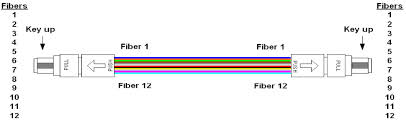
Figure 17-6 shows a Type A straight through ribbon cable with 12 fibers terminated in MPO connetor. A Method A backbone link is cabled “straight through”, terminating in the cabling system patch panel. One end of the link will have a straight through patch cable, connetion from the patch panel to the Ethernet interface. The other end of the link will have a crossover cable connecting to the Ethernet interface. The guidelines recommend keeping all of the crossover patch cables at one end of the link, to keep the system as simple as possible and help the installer to avoid connecting the wrong type of patch cale.

MPO Fiber

The guidelines also show Method B and Method C, which are two methods for providing a crossover patch built into the MPO backbone cables themselves. Given the complexity of these approaches and the difficulty of implementing them correctly, they are both rarely used.

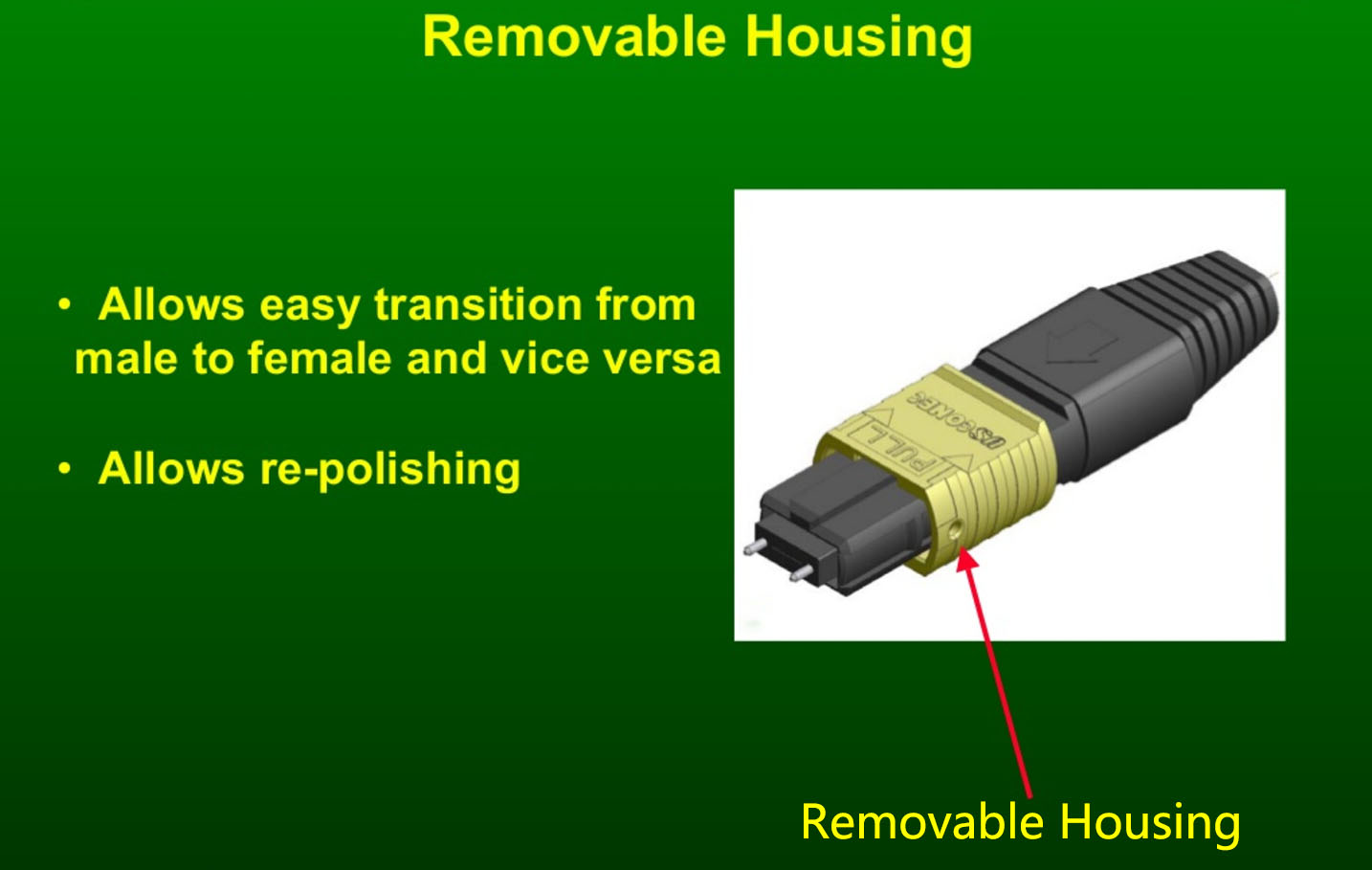
As you can see, there are a variety of approaches to managing the signal crossover for the 12-fiber and 24-fiber systems needed to support 40 and 100 Gb/s Ethernet. For the best results, make sure you know which method your site is using in the cabling system, and order the correct MPO cable types to make the connections and achieve the signal crossover. Note that some vendors provide special MPO connectors that make it possible to change connector gender and polarity(crossover) in the field, which coulde be a handy way to resolve MPO-to-MPO connectivity issues.

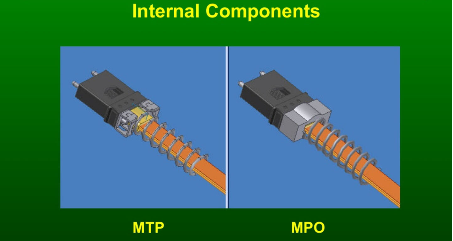
To provide an introduction and basic information to readers, this section begins with a presentation of the components needed for a parallel optical MPO connection.

MPO connectors contact up to 24 fibers in a single connection. A connection must be stable and its ends correctly aligned. These aspects are essential for achieving the required transmission parameters. A defec-tive connection may even damage components and or cause the link to fail altogether.

MPO cables are delivered already terminated. This approach requires greater care in planning in advance but has a number of advantages: shorter installation times, tested and guaranteed quality and greater reli-ability.

Fiber trunk cables serve as a permanent link connecting the MPO modules to each other. Trunk cables are available with 12, 24, 48 and 72 fibers. Their ends are terminated with the customer’s choice of 12-fiber or 24-fiber MPO connectors.

trunk fiber optic cables

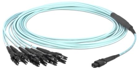
Harness cables provide a transition from multi-fiber cables to individual fibers or duplex connectors.The 12-fiber harness cables available from R&M are terminated with male or female connectors on the MPO side, the whips are available with LC or SC connectors.

Harness cable

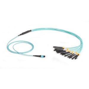
Fiberstore supply MTP MPO fiber cables, MTP Cassette and MPO Cassette.  MTP MPO cables are available in 4,8,12, 24, and 48 fiber array configurations.  Many additional options and combinations are available. All fiber optic cables are customizable.

International Wire And MTP MPO Cable Symposium

Share

Harnesses are custom-engineered to allow seamless integration into various Storage Area Network (SAN) directors. Harnesses are used to transition the 12-fiber MPO connectors into LC connectors. A pinned MPO connector on one end connects to a trunk through a connector panel in the housing, while the other end is equipped with six LC-style uniboot connectors, which plug into optoelectronic ports.

As with jumpers, bend-insensitive fiber reduces the cable diameter and allows for the uniboot design described above. Additionally, the new fiber allows for an innovative new design of the harness furcation, resulting in the overall length reduction of the furcation. The bend-insensitive fiber also eliminates the need for bend radius control components at both the front and rear of the furcation such as segmented boots, heat shrink,spiral wraps and other such support. Likewise, this allows for precision staggering of the harness legs without using the above-mentioned radius control components. MPO connector leg slack can be stored in the vertical manager without fear of inducing macrobend attenuation loss. Figure 21 shows an engineered uniboot harness, Figure 22 shows the harness installed in the equipment rack, and Figure 23 shows the harness connected to a 48-port blade server.

The use of harnesses provides an innovative solution that occupies less space than traditional jumpers as the cable end of the harness is much smaller than the 12 equivalent patch cords. This reduced cabling bulk improves airflow for increased cooling and facilitates easier moves, adds and changes (MACs).

In typical data center applications, trunk cable branch into 12-fiber legs at a furcation plug that provides cable demarcation and strain relief. Each leg is equipped with an MPO connector, which is a 12-fiber push/pull optical connector with a footprint similar to the SC simplex connector. These high-density connectors are used to significantly accelerate the network installation process, minimize errors and reduce space. Trunks in data center applications utilizing MPO connectors typically support 12 to 144 fibers. Figure 24 shows a 144-fiber trunk cable assembly with a pulling grip on one end for ease of installation.

Through the use of bend-insensitive fibers in micro-module cable designs, trunk cables are on average 30 percent smaller in outer diameter. In addition, the minimum bend radius is now five timesthe outer diameter of the cable compared to 10 times the diameter in traditional trunks. Smaller-diameter trunks allow for more than 50 percent more cables to be stored in cable trays, while minimizing cable tray weight and impediments to cooling air.The smaller bend radius allows for extra cable slack to be stored without interfering with cable routing or causing attenuation that may adversely impact system performance.

Plug & Play Universal Systems utilize the MTP® Connector. The MTP Connector is a multi-fiber array-style connector that can accommodate up to 12 fibers in roughly
the same size and footprint as an SC connector. It has a single high-density footprint of 25 x 10 mm and features simple push-on/pull-off mating. A general industry term for this style of connector is MPO. This connector, which is used in both multimode and single-mode applications,maximizes valuable panel and hardware space, ensuring high density. MTP Connectors are manufactured with either alignment pins or with alignment holes to ensure proper alignment of the fibers. A connector with alignment pins always mates with a connector with alignment holes. (Figure 7.1). The MTP Connector offers:

• Up to 54 percent reduction in pathway congestion
• Modularity and scalability with a fiber count that maps to current and future line-card port counts
• Universal wiring and superior loss performance for migration to higher data rates

A traditional Plug & Play Universal Systems trunk consists of an optical cable with each end factory-terminated with MTP Connectors and a pulling grip on one or both ends.Trunks are available in a variety of fiber types and typically carry a plenum rating unless otherwise specified. When ordering Plug & Play Universal Systems trunks, the MTP Connectors on both ends will have pin alignment holes. This ensures that it will integrate with the remaining parts of the system that have pins. It should be noted that MTP Connector panels have neither pins nor alignment holes, as they are connection points for various components of the Plug & Play Universal Systems.

To successfully deploy a cable that is preterminated on both ends, it is necessary to accurately predetermine the installed link length. This can be relatively straightforward if welldefined pathways and spaces exist for the cable route, which is usually true for the data center environment. If the route is less defined, preterminated cables can still be utilized by specifying the trunk cables be longer than the known length and planning for the storage of excess cable loops.

MTP VS MPO: What’s the Difference?

Share

In regard to multi-fiber connector, many will think of MTP connector while the others will think it is MPO connector. In most cases, these two kinds of connectors can be considered the same. Actually, they are a little different not only in names but also in some other aspects. MTP VS MPO: what’s the difference? This post will clarify the differences between these two.

MTP VS MPO: What’s an MPO Connector?

As the industry acronym for “Multi-fiber Push On”, MPO is developed to provide multi-fiber connection in one connector to support higher bandwidth and higher density applications. MPO connector is standardized in the international regulatory framework (the IEC 61754-7 standard) and the U.S. (TIA-604-5 Standard ). At present, the most common fiber counts are 12 and 24, and 48 to 72 fiber counts are also possible in limited applications.

mtp vs mpo

MTP VS MPO: What’s an MTP Connector?

MTP is a registered trade mark of US Conec. In other words, MTP connector is used by US Conec to describe their multi-fiber connector initially. Now MTP is commonly referred to as a high performance MPO connector. So MTP connectors are fully compliance with all generic MPO connectors and can interconnect directly with other MPO based infrastructures.

MTP VS MPO: What’s the Difference?

As mentioned above, MTP connector is an enhanced version of MPO connector. This means Generic MPO connectors are limited in performance and are not able to offer the high performance levels of MTP connectors. Generally, MTP connectors are superior to generic MPO connectors in the following aspects:

Mental Pin Clamp

The MTP connector has a metal pin clamp to ensure a strong clasp on the pins and minimize any inadvertent breaking when mating connectors. While MPO connectors are often manufactured with inferior plastic pin clamps which may lead to effortless breaking of pins with constant cable mating.

MTP VS MPO: pin clamp

Floating Ferrule

An important feature of MTP is its floating ferrule, which will help to improve mechanical performance. To be specific, The MT ferrule of MTP connectors can float inside to keep physical contact over a mated pair under an applied load. Generic MPO connector do not have this ferrule float feature.

Elliptical Shaped Guide Pins

MTP connectors use tightly held tolerance stainless steel elliptical guide pin tips to reduce guide hole wear. Unlike single fiber connectors, the adapters for multi-fiber connectors are only for coarse alignment. Thus the guide pins are critical for accurate alignment when mating two MT ferrules. The elliptical shaped pins of MTP connectors does not chip the ferrule material which helps to reduce the amount of debris that may fall into the guide pin holes or on the ferrule end face. Generic MPO connectors have chamfered shaped guide pins which will produce more debris when used.

MTP VS MPO: guide pin

Removable Housing

The MTP connector is designed to have a removable housing. This allows users to re-work and re-polish the MT ferrule, to easily get access to performance testing and to smoothly change the gender after assembly or even in the field.

MTP removable housing

Higher Optical Signal Performance

The generic MPO connector is recognized as an international standard for network architects who require density and strive for shorter install times, as well as simplified cabling infrastructure for their 40G/100G data centers. However, in higher fiber count MPO cabling, using MPO connectors will have problems with optical loss (measured in dB), dropped packets and diminished network visibility.

The MTP connector is a high performance MPO connector with multiple engineered product enhancements to improve optical and mechanical performance. It is designed to ensure the precision alignment of the female and male sides. This is critical to reducing insertion loss and return loss in dense, multi-mode fiber connectivity. MTP/MPO connector

Conclusion

MTP VS MPO: Do you know the differences between them now? They are both widely used in high density cabling networks, especially in 40G/100G data centers. MPO is an internationally recognized standard interface for connector manufacturers. While MTP is one type of MPO connector. It is a brand owned by US Conec. If you are planning to build a multi-fiber network, a cable with MTP connectors will give you the best over-life performance. MPO connectors will also work, but may not perform to the same level.

Related Article: MTP/MPO Connector: Difference And Cleaning Recommendation

                           MTP/MPO Cable Assembly – the Game Changer of Data Center Cabling