Category Archives: Fiber Optic Transceivers

Can I Use SFP Transceiver in SFP+ Slot?

Share

A common confusion about SFP and SFP+ compatibility is that if I can use the SFP module in SFP+ slot. When I connect the SFP transceiver to SFP+ transceiver, can SFP+ negotiate down to 1G? Or is it possible to use SFP+ module in the SFP port on my switch? Can SFP+ copper twinax cable can negotiate down to 1G to support SFP? Can 1G and 10G can exist in the same link? All these questions usually create a giant headache for many engineers. After looking up many relevant documentation, now I will conclusion the answers in this article.

SFP Can be Plugged into SFP+ Ports in Most Situations
I’m not sure about the specific switch model, but as a general rule of thumb, SFPs will work in SFP+ slot, but SFP+ optics do not work in SFP slots. It’s just a power availability thing. When you plug the SFP module in SFP+ port, the speed of this port is 1G not the 10G. And sometimes this port will lock the speed at 1G until you reload the switch or do some fancy set of commands. Besides, the SFP+ port usually can never support speed under 1G. That is to say, we can’t plug the 100BASE SFP in the SFP+ port. In fact, for this question, it may depend greatly on the switch models – sometimes SFPs are supported in SFP+ ports, and sometimes not. For example, almost all SFP+ ports of Cisco switch can support SFPs and many SFP+ ports of Brocade switch only support SFP+. Though it’s feasible often, it’s safer to ask your switch vendor for some information.

SFP module in SFP+ port

SFP+ Can’t Auto-negotiate Down to 1G to Support with SFP Module
To my knowledge, unlike copper SFPs which are available in 10/100/1000 auto-negotiation, optics such as SFP and SFP+ do not support auto negotiation at all. In fact, Most (95+%) SFPs and SFP+s will only run at the rated speed, no more, no less. Besides, there is no such thing as a SFP+ that does 1G on one side (towards the fiber) and then does 10G on another side (towards the unit). Though we can use SFP in SFP+ ports in many cases, that doesn’t mean a SFP+ plugged into the SFP+ slot can support 1G. In a fiber link, if we plug a SFP in the SFP+ port on one side (1G), and then plug a SFP+ in the SFP+ port on the another side (10G), this may not work! You just can’t have 10 GbE at one end and 1 GbE at the other. For this question, if you use SFP+ copper, it also can’t negotiate down to 1G.

When use SFP and SFP+ modules in your network, make sure the speed of both ends of the fiber link is the same. SFP modules may can be used in SFP+ slot, but a SFP can never be connected to a SFP+ module. For their different speeds, transmission distance and wavelength. 10 SFP+ only can use for 10G SFP+ port, and can never auto-negotiate to 1G.

Related Article: Can I Use the QSFP+ Optics on QSFP28 Port?

Related Article: SFP Module: What’s It and How to Choose It?

Related Article: Understanding Video SFP Transceivers

Compatible SFPs for Ubiquiti EdgeSwitch and UniFi switch

Share

The Ubiquiti EdgeSwitch targets the Broadband / ISP / Carrier market, which offers an extensive suite of advanced layer-2 switching features and protocols, and also provides layer-3 routing capability. The UniFi switch targets the Enterprise / SMB market, which is designed for a wider IT audience, and therefore, tend to be simpler, and easier to use. Both these two types Ubiquiti switchs are supported for SFP fiber connectivity and widely used among people. However, which SFPs can I use with my EdgeSwitch or UniFi switch? This article may give the answer on ubiquiti SFP compatibility.

Which Ubiquiti EdgeSwitch Should I Use?

The EdgeSwitch offers the forwarding capacity to simultaneously process traffic on all ports at line rate without any packet loss. The EdgeSwitch provides total, non-blocking throughput. Among 8-Port model up to 10 Gbps, 16-Port model up to 18 Gbps, 24-Port model up to 26 Gbps and 48-Port model up to 70 Gbps. The following table lists the comparison between EdgeSwitch modules, according to your specific need to choose the right one.

Model Total Non-Blocking Throughput Gigabit RJ45 Ports SFP+ Ports SFP Ports Max. Power Consumption
ES- 8- 150W 10 Gbps 8 N/A 2 150W
ES- 16- 150W 18 Gbps 16 N/A 2 150W
ES- 24- 250W 26 Gbps 24 N/A 2 250W
ES- 24- 500W 26 Gbps 24 N/A 2 500W
ES- 48- 500W 70 Gbps 48 2 2 500W
ES- 48- 750W 70 Gbps 48 2 2 750W
ES- 24- LITE 26 Gbps 24 N/A 2 25W
ES- 48- LITE 70 Gbps 48 2 2 56W
ES- 12F 16 Gbps 4 N/A 12 56W
ES- 16- XG 124 Gbps 4 12 N/A 56W
EdgeMAX – Which SFPs are compatible with EdgeSwitch?

The ubnt edgeswitch provides fiber connectivity options for your growing networks. The 8, 16, and 24-port models include two SFP ports, providing up to 1 Gbps uplinks. For high-capacity uplinks, the 48-port models include two SFP and two SFP+ ports, providing uplinks of up to 10 Gbps. Take the ES‑8‑150W for example, it has 8 Gigabit RJ45 ports and 2 Gigabit SFP ports for 10G applications (shown in the figure below). For SFP ports, we should use SFP modules and fiber patch cable.

edgeswitch
According to an article titled “Which SFPs are compatible with the EdgeSwitch?”published in Ubiquiti Help Center, the following SFP transceivers are compatible with EdgeSwitch (only listed can be found in Fiberstore here).

SFP Model Description
Cisco GLC-SX-MM 1000BASE-SX SFP 850nm 550m Transceiver
Cisco GLC-SX-MMD 1000BASE-SX SFP 850nm 550m DOM Transceiver
HP J4858C 1000BASE-SX SFP 850nm 550m DOM Transceiver
HP J4858A 1000BASE-SX SFP 850nm 550m DOM Transceiver
Cisco GLC-LH-SM 1000BASE-LX/LH SFP 1310nm 10km Transceiver
HP J4859B 1000BASE-LX SFP 1310nm 10km DOM Transceiver
HP J4859C 1000BASE-LX SFP 1310nm 10km DOM Transceiver
Cisco GLC-T 1000BASE-T SFP Copper RJ-45 100m Transceive
Cisco SFP-H10GB-CU1M 1m 10G SFP+ Passive Direct Attach Copper Twinax Cable
Brocade 10G-SFPP-TWX-0101 1m 10G SFP+ Passive Direct Attach Copper Twinax Cable
Which Ubiquiti UniFi Switch Should I Use?

The UniFi POE switch offers the forwarding capacity to simultaneously process traffic on all ports at line rate without any packet loss. For its total, non-blocking throughput, the 24port model supports up to 26 Gbps, while the 48-port model supports up to 70 Gbps. The following table lists the comparison between UniFi switch modules, according to your specific need to choose the right one.

Model Total Non-Blocking Throughput Gigabit RJ45 Ports SFP+ Ports SFP Ports Max. Power Consumption
US- 8- 150W 10 Gbps 8 N/A 2 150W
US- 16- 150W 18 Gbps 16 N/A 2 150W
US- 24- 250W 26 Gbps 24 N/A 2 250W
US- 24- 500W 26 Gbps 24 N/A 2 500W
US- 48- 500W 70 Gbps 48 2 2 500W
US- 48- 750W 70 Gbps 48 2 2 750W
UniFi – Which SFPs are compatible with UniFi Switch?

Each model includes two SFP ports for uplinks of up to 1 Gbps. The 48port model adds two SFP+ ports for high-capacity uplinks of up to 10 Gbps, so you can directly connect to a highperformance storage server or deploy a longdistance uplink to another switch. Take the US- 8- 150W for example, it has 8 Gigabit RJ45 ports and 2 Gigabit SFP ports for 10G applications (shown in the figure below). For SFP ports, we should use SFP modules and fiber patch cable.

us-8-150w
According to an article titled “Which SFPs can I use with UniFi switch?”published in Ubiquiti Help Center, the following SFP transceivers are compatible with EdgeSwitch. Since among some SFP module types are the same as the EdgeSwitch, I only list the different SFPs here.

SFP Model Description
Fiberstore SFP-1G85-5M

Now: SFP1G-SX-85

1000BASE-SX SFP 850nm 550m DOM Transceiver
Cisco SFP-10G-SR 10GBASE-SR SFP+ 850nm 300m DOM Transceiver
Fiberstore SFP-10G85-3M

Now:
SFP-10GSR-85

10GBASE-SR SFP+ 850nm 300m DOM IND Transceive
Ubiquiti SFP Compatibility: Ubiquiti Compatible SFPs in Fiberstore

Fiberstore (FS.COM) provides a series of Ubiquiti compatible SFP transceivers that can be used with EdgeSwitch and UniFi switch. In Ubiquiti Networks Community SFP modules compatibility section, some people tested Fiberstore SFP modules in their EdgeSwitch. As shown in the figure below, SFP1G-SX-85, SFP1G-SX-31 and SFP-10GSR-85 SFPs are working.

sfp-modules-compatibility

Related Article: 3rd Party Optical Transceivers vs OEM Switch Warranty

What Is The Difference: SFP vs SFP+

Share

As we know, a SFP module just looks the same as the SFP+ module. And most switches can both support SFP module and SFP+ module. So, do these two modules really refer to the same one? What’s the difference between SFP vs SFP+?

SFP vs SFP+

SFP vs SFP+: SFP Definition
SFP stands for Small Form-factor Pluggable. It is a hot-pluggable transceiver that plugs into the SFP port of a network switch and supports SONET, Gigabit Ethernet, Fibre Channel, and other communications standards. SFP specifications are based on IEEE802.3 and SFF-8472. They are capable of supporting speeds up to 4.25 Gbps. Due to its smaller size, SFP replaces the formerly common gigabit interface converter (GBIC). Therefore SFP is also called Mini-GBIC. By choosing different SFP module, the same electrical port on the switch can connect to different fiber types (multimode or single-mode) and different wavelengths.

SFP module Cisco

SFP vs SFP+: SFP+ Definition
Since SFP supports only up to 4.25 Gbps, SFP+ that supports data rates up to 16 Gbps was later introduced. In fact, SFP+ is an enhanced version of the SFP. The SFP+ specifications are based on SFF-8431. In today’s most applications, SFP+ module usually supports 8 Gbit/s Fibre Channel, 10 Gigabit Ethernet and Optical Transport Network standard OTU2. In comparison to earlier 10 Gigabit Ethernet XENPAK or XFP modules, SFP+ module is smaller and becomes the most popular 10 Gigabit Ethernet module in the market.

SFP+ module Cisco

SFP vs SFP+
Review the SFP and SFP+ definition mentioned above, we can know that the main difference between SFP and SFP+ is the data rate. And due to different data rate, the applications and transmission distance is also different.

Ethernet Application

SFP (1Gbps) SFP+ (10Gbps)
1000BASE-SX SFP 850nm 550m

1000BASE-LX/LH SFP 1310nm 20km

1000BASE-EX SFP 1310nm 40km

1000BASE-ZX SFP 1550nm 80km

10GBASE-SR SFP+ 850nm 300m

10GBASE-LRM SFP+ 1310nm 220m

10GBASE-LR SFP+ 1310nm 10km

10GBASE-ER SFP+ 1550nm 40km

10GBASE-ZR SFP+ 1550nm 100km

Fiber Channel Application

SFP (2G, 4G) SFP+ (8G)
2.125Gbps:

2G Fibre Channel SFP 1310nm 2km/15km/20km/40km

2G Fibre Channel SFP 1510nm 80km

4.25Gbps:

4G Fibre Channel SFP 850nm 150m

4G Fibre Channel SFP 1310nm 5km/10km/15km/20km

8.5Gbps:

8G Fibre Channel SFP+ 850nm 150m

8G Fibre Channel SFP+ 1310mn 10km/20km/40km

8G Fibre Channel SFP+ 1510nm 80km

SONET/SDH Application

SFP (155Mbps, 622Mbps, 2.5Gbps) SFP+ (10G)
155Mbps:

OC-3/STM-1 1310nm 2km/15km/40km

OC-3/STM-1 1510nm 80km

622Mbps:

OC-12/STM-4 1310nm 500m/2km/15km/40km

OC-12/STM-4 1510nm 80km

2.5Gbps:

OC-48/STM-16 1310nm 2km/15km/40km

OC-48/STM-16 1510nm 80km

OC-192/STM-64 850nm 300m

OC-192/STM-64 1310nm 2km/10km/20km/40km

OC-192/STM-64 1510nm 80km

As we’ve explained the difference of SFP vs SFP+. Usually, SFP module plugs into SFP port of the switch and SFP+ module plugs into SFP+ port of the switch. But, sometimes SFP module can also be plugged into SFP+ port. Which SFP or SFP+ module should you choose all depends on your switch types. Fiberstore is a reliable SFP transceiver module manufactures, all SFP module and SFP+ module types are available in FS.COM. Besides, SFP+ cable is also provided. What’s more, the price of SFP module and SFP+ module is lower than many other manufactures. SFP test is strict in FS.COM. Matching fiber patch cable is also available.

Related Article: Compatible SFPs for Ubiquiti EdgeSwitch and UniFi switch

Related Article: SFP Module: What’s It and How to Choose It?

Related Article: Understanding Video SFP Transceivers

How to Choose SFP+ Transceivers for Cisco 4500 Series Switch

Share

The Cisco 4500 series switches provide high performance, mobile, and secure user experiences through Layer 2-4 switching investments. Since they have a centralized forwarding architecture that enables collaboration, virtualization, and operational manageability through simplified operations, therefore, more and more people choose to use 4500 series switch in their network. As we know, once we use a network switch, we may use some transceiver modules. In this article, some SFP+ transceivers that supported for Cisco 4500 series switch will be introduced.

Cisco 4500 Series Switch Overview
Cisco 4500 series switch include 4500 Series and 4500E Series switch. Among, 4500 series include Catalyst 4503 Switch, Catalyst 4506 Switch, Catalyst 4507R Switch, Catalyst 4510R Switch. With forward and backward compatibility spanning multiple generations, the new Cisco Catalyst 4500E Series provides exceptional investment protection and deployment flexibility to meet the evolving needs of organizations of all sizes, which include Catalyst 4503-E Switch, Catalyst 4506-E Switch, Catalyst 4507R+E Switch and Catalyst 4510R+E Switch. SFP+ ports operate in full-duplex mode and are present on the WS-X4516-10GE and WS-X4013+10GE supervisors, as well as some line cards. These ports use the 10GBASE-SR, 10GBASE-LRM and 10GBASE-LR SFP+. SFP+ connectors vary with interface type and may use multimode fiber (MMF) or single-mode fiber (SMF) cable.

cisco 4500

Supervisor Engine for Cisco 4500 Series Switch
The Cisco supervisor engine is the brain of many of Cisco’s switches, which refers to specific modules that can be placed in a modular chassis. Cisco 4500 series and 6500 series switch both require supervisor engines to work. In fact, the transceivers type depends on the port type of supervisor engine. So, it’s necessary to identify the port type of your supervisor engines first. In following table, I display some supervisor engines that both supported for Catalys 4500 series switch and SFP+ transceivers. Please note that WS-X4516-10GE, WS-X4013+10GE, WS-X45-Sup6-E, WS-X45-Sup6L-E and WS-X4606-X2-E can also be used for X2 transceivers with CVR-X2-SFP10G converter.

Cisco Catalyst 4500 Series Supervisor Engine V-10GE
WS-X4516-10GE 2×10 Gigabit Ethernet (X2 or SFP+) or 4X1 Gigabit Ethernet (SFP)
Cisco Catalyst 4500 Series Supervisor Engine II-Plus-10GE
WS-X4013+10GE 2x10GE (X2 or SFP+) and 4×1 Gigabit Ethernet (SFP)
Cisco Catalyst 4500E Supervisor Engine 6-E And 6L-E
WS-X45-Sup6-E 2×10 Gigabit Ethernet (X2 or SFP+) or 4×1 Gigabit Ethernet (SFP), Console RJ-45, USB
WS-X45-Sup6L-E 2×10 Gigabit Ethernet (X2 or SFP+) or 4×1 Gigabit Ethernet (SFP), Console RJ-45
Cisco Catalyst 4500E Series Line Cards
WS-X4606-X2-E 6×10 Gigabit Ethernet (X2 or SFP+)
WS-X4712-SFP+E 12×10 Gigabit Ethernet (SFP+)
Cisco Catalyst 4500E Series Supervisor Engine 7-E And 7L-E
WS-X45-SUP7-E 4×10 Gigabit Ethernet uplinks (SFP+)
WS-X45-SUP7L-E 2×10 Gigabit Ethernet uplinks (SFP+) or 4×1 Gigabit Ethernet uplinks (SFP)
Cisco Catalyst 4500E Series Supervisor Engine 8-E And 8L-E
WS-X45-SUP8-E 8×10 Gigabit Ethernet uplinks (SFP+)
WS-X45-SUP8L-E 4×10 Gigabit Ethernet uplinks (SFP+) or 4×1 Gigabit Ethernet uplinks (SFP)

SFP+ Transceivers for Cisco 4500 Series Switch
According to Cisco 10-Gigabit Ethernet Transceiver Modules Compatibility Matrix, all supervisor engines mentioned above can support SFP-10G-SR, SFP-10G-LRM, SFP-10G-LR, SFP-10G-SR-S and SFP-10G-LR-S SFP+ transceivers. Besides, WS-X4712-SFP+E, WS-X45-SUP7-E, WS-X45-SUP7L-E, WS-X45-SUP8-E and WS-X45-SUP8L-E can also support SFP-10G-ER, SFP-10G-ZR, SFP-10G-ER-S and SFP-10G-ZR-S SFP+ transceivers. All SFP+ transceievrs can be found in FS.COM.

WS-X4516-10GE, WS-X4013+10GE, WS-X45-Sup6-E, WS-X45-Sup6L-E, WS-X4606-X2-E, WS-X4712-SFP+E, WS-X45-SUP7-E, WS-X45-SUP7L-E, WS-X45-SUP8-E and WS-X45-SUP8L-E
SFP-10G-SR Cisco SFP-10G-SR Compatible 10GBASE-SR SFP+ 850nm 300m DOM Transceiver, $ 16
SFP-10G-LRM Cisco SFP-10G-LRM Compatible 10GBASE-LRM SFP+ 1310nm 220m DOM Transceiver, $ 34
SFP-10G-LR Cisco SFP-10G-LR Compatible 10GBASE-LR SFP+ 1310nm 10km DOM Transceiver, $ 34
SFP-10G-SR-S Cisco SFP-10G-SR-S Compatible 10GBASE-SR SFP+ 850nm 300m DOM Transceiver, $ 16
SFP-10G-LR-S Cisco SFP-10G-LR-S Compatible 10GBASE-LR SFP+ 1310nm 10km DOM Transceiver, $ 34
WS-X4712-SFP+E, WS-X45-SUP7-E, WS-X45-SUP7L-E, WS-X45-SUP8-E and WS-X45-SUP8L-E
SFP-10G-ER Cisco SFP-10G-ER Compatible 10GBASE-ER SFP+ 1550nm 40km DOM Transceiver, $ 180
SFP-10G-ZR Cisco SFP-10G-ZR Compatible SFP+ 1550nm 80km DOM Transceiver, $ 400
SFP-10G-ER-S Cisco SFP-10G-ER-S Compatible 10GBASE-ER SFP+ 1550nm 40km DOM Transceiver, $ 180
SFP-10G-ZR-S Cisco SFP-10G-ZR-S Compatible 10GBASE-ZR SFP+ 1550nm 80km DOM Transceiver, $ 400

Related Articlea:

How to Choose SFP+ Transceivers for Cisco 4500 Series Switch

Cisco SFP-10G-SR: All You Need to Know


SFP+ Fiber vs SFP+ Twinax Cable vs 10GBASE-T, Which to Choose for 10G?

Share

When you’ve selected the server, storage and switch to setup your data center, then how do you connect it all together? There’s no doubt that the answer is “with cables.” Let’s look at the three most common cables that used to connect the servers and storage to switches in a 10G network. They are SFP+ fiber solution (used with LC fiber patch cable), SFP+ twinax cable and 10GBASE-T solution. Which one should you choose? Let’s find the answer together!

SFP+ Fiber Solution
This connection methods requires two things on each device: 10G pluggable SFP+ transceiver and fiber optic patch cable. Once these are in place on both devices (server and switch), you can plug the patch cords into the transceiver on both sides. These SFP+ optical transceivers use approximately 1W per transceiver and have a latency of less than 0.1 microsecond. SFP+ transceiver comes in different types to drive signals across fiber optic cables with different maximum distances. The most common, and lowest in cost, is 10GBase-SR, which can span 300 meters. Other types can reach as far as 100 kilometers.

SFP+ transceivers

Pros: This connectivity method supports fiber cables that are really long, allowing you to connect a server at one end of a data center to a switch several racks away or even at the other end.
Cons: Pluggable transceiver parts are quite expensive.

SFP+ Twinax Cable
SFP+ twinax direct attach cable (DAC) integrates transceivers with twinax cable into an energy efficient, low-cost, and low-latency solution. It features SFP+ connectors on both ends, thus eliminating the need for expensive SFP+ transceivers. SFP+ twinax cables use only 1.5 watts of power per port and introduce only approximately 0.25 microsecond of latency per link. This makes it an optimal solution for handling high bandwidth transmission within short distances such as inside energy-efficient data centers.

SFP+ Twinaxial Cable

Pros: Lower latency, lower power and lower heat.
Cons: Transmission distance is usually less than 10 meter.

10GBASE-T Solution: Cat6 Copper Cable
This option probably looks familiar – like the RJ-45 ports and cabling you use to connect your laptop to a normal network jack. The difference is that you need specialized network adapters with ports that support faster 10G throughput. Cat6 cables have more individual copper wires, twisted tighter, with better shielding to prevent outside signal interference. They cost more than CAT5 but ensure better signal communication, which is a requirement to speed up to 10G. Cat6 copper cables use 5 watts of power per port and introduce approximately of latency per link, which is much higher than SFP+ optics and SFP+.

10GBASE-T structured-cabling

Pros: Longer distance – 100 meters. Backward compatibility to 1 gigabit Ethernet or 100 megabit Ethernet
Cons: Higher latency, higher power and higher heat. Not many data center switches support 10GBASE-T ports.

Conclusion
Vita differences of these three 10G cabling solutions are displayed in the table below. According to your demands to choose the right one.

Name Transmission Distance Latency Power
SFP+ Fiber Solution 300 m – 100 km 0.1 microsecond 1 watts
SFP+ Twinax Cable 10 m 0.25 microsecond 1.5 watts
10GBASE-T Solution 100 m 2.6 microsecond 4 – 6 watts

QSFP+ and QSFP28 Transceivers Cabling Solutions

Share

The short range 40-Gigabit Ethernet QSFP+ and 100-Gigabit Ethernet QSFP28 transceivers that are widely used in today’s data center use 12-fiber patch cables with female MPO connectors. The fiber can be either OM3 or OM4. The long range QSFP+ and QSFP28 transceiver use single-mode fiber patch cables with duplex LC connectors. This article may introduce the cabling solutions for QSFP+ and QSFP28 transceiver to you.

QSFP+ and QSFP28 Transceiver Types
In terms of 40G QSFP+ transceivers, from short range to long range, they are available in 5 common types. The minimum transmission distance is 100m, and the max transmission distance is 40km. 100G QSFP28 transceivers are commonly avaiable in 100GBASE-SR4 and 100GBASE-LR4 two types. Detailed QSFP+ and QSFP28 transceiver specifications are displayed in following tables.

Transceiver Type Interface Standard Connector Type Fiber Type
QSFP+ 40GBASE-SR4 Female MTP/MPO, key up 12-fiber multi-mode fiber (MMF) (OM3 or OM4)
QSFP+ 40GBASE-PLRL4 Female MTP/MPO, key up 12-fiber single-mode fiber (SMF) 1km
QSFP+ 40GBASE-PLR4 Female MTP/MPO, key up 12-fiber SMF 10km
QSFP+ 40GBASE-LR4 LC duplex SMF 10km
QSFP+ 40GBASE-ER4 LC duplex SMF 40km
QSFP28 100GBASE-SR4 Female MTP/MPO, key up 12-fiber MMF (OM3 or OM4)
QSFP28 100GBASE-LR4 LC duplex SMF 10km

12-Fiber Patch Cables with MTP Connectors
12-fiber patch cables with MTP connectors can be used to connect two transceivers of the same type—40GBASE-SR4-to-40GBASESR4 or 100GBASE-SR4-to-100GBASE-SR4. You can also connect 4x10GBASE-LR transceivers such as 40GBASE-PLRL4 and 40GBASE-PLR4 using patch cables—4x10GBASE-LR-to-4x10GBASE-LR—instead of breaking the signal out into four separate signals. Ensure that you order cables with the correct polarity. The MTP connectors on the 12-fiber cables should be key up (sometimes referred to as latch up, Type B, or Method B). If you are using patch panels between two QSFP+ or QSFP28 transceivers, ensure that the proper polarity is maintained through the cable plant.

12-Fiber MTP Patch Cables

12-Fiber MPO Patch Cables

12-Fiber Breakout Cables with MTP-LC Duplex Connectors
12-fiber breakout cables with MTP-LC duplex connectors can be used to connect a 4x10GBASE-LR or 4x10GBASE-SR transceiver to four separate 10GBASE-LR or 10GBASE-SR SFP+ transceivers. The breakout cable is constructed out of a 12-ribbon fiber-optic cable. The breakout cable splits from a single cable with an MTP connector on one end, into 4 cable pairs with 4 LC duplex connectors on the opposite end.

40G QSFP+ and 100G QSFP28 transceivers solution

40G to 4×10G

LC Duplex Patch Cables
Single-mode patch cables with LC duplex connectors can be used to connect two transceivers of the same type—40GBASE-LR4-to-40GBASE-LR4 or 100GBASE-LR4-to100GBASE-LR4. The SMF patch cable is one fiber pair with two LC duplex connectors at opposite ends.

LC Duplex Patch Cables

Related Article: Can I Use the QSFP+ Optics on QSFP28 Port?

Data Center Upgrade — Who Should Be Responsible for Buying Transceivers?

Share

There was a time that cable products specifically associated with hardware OEMs. If a company was buying or using one of these vendors’ products, the matching cables also had to be used. Therefore, whoever was responsible for managing the hardware was also responsible for the cabling used to connect the devices together. Then, the structured cabling industry replaced this. The cabling infrastructure is now viewed as an independent asset separate from the IT hardware. This has allowed companies to make purchasing decisions for IT and cabling without the concern of each other. But this may be a problem. To understand the problem, let’s understand the LAN network operation principles first.

transceiver

The OSI Model of LAN Network
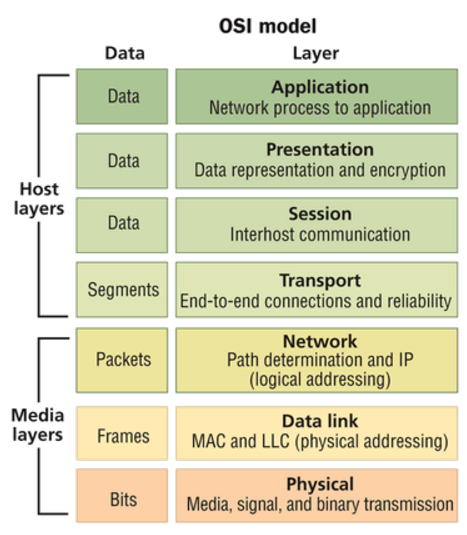
As we know, the operation of local area networking (LAN) was defined with the Open Systems Interconnection Reference Model (OSI Model). The OSI Model defined seven layers of operation. By using the model, the industry could develop networking functions in a modular fashion and still ensure interoperability. The bottom of the stack is Layer 1, the Physical Layer. Layer 1 includes the cabling that is used to connect the various pieces of equipment together so that the data can be transported. The next step up on the stack is Layer 2, the Data Link Layer. Layer 2 provides for addressing and switching, so that the data can be sent to the appropriate destination. Layer 3 is the Network Layer, where data can be routed to another network. Layers 4 through 7 deal with software implementations.

OSI Model
The OSI Model meant that an end-user could purchase software (Layer 7) and expect it to work on multiple vendors’ hardware (Layer 2). And the hardware could be connected using multiple vendors (Layer 1). Structured cabling now had a home within Layer 1. Then this module leads to division of responsibility, for cabling versus network design specifications. The end-user ended up having “cabling people” and “networking people” on their staff. Each group of people used their own set of vendors and supply chains to specify and source their materials. And they each only needed a very basic understanding of what the other people were doing. This system has worked very well for the enterprise LAN. So what’s the problem?

What Is the Problem?
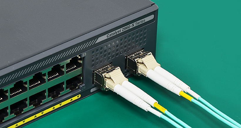
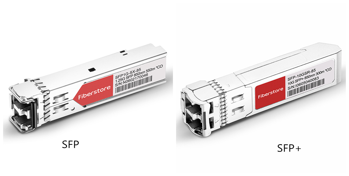
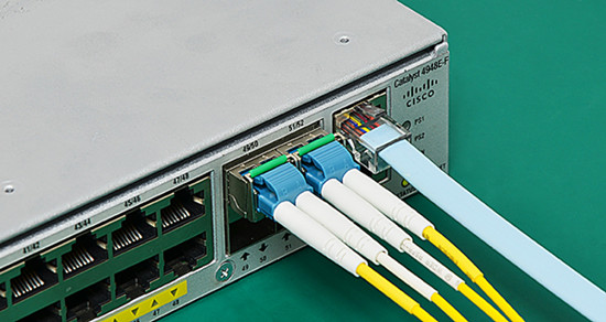
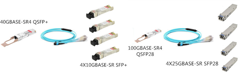
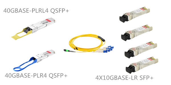
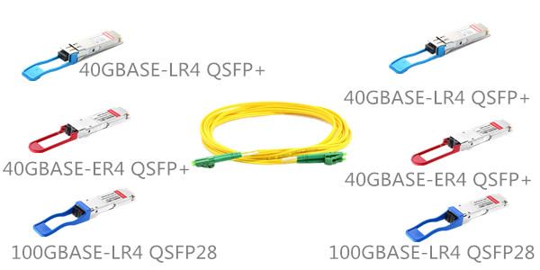
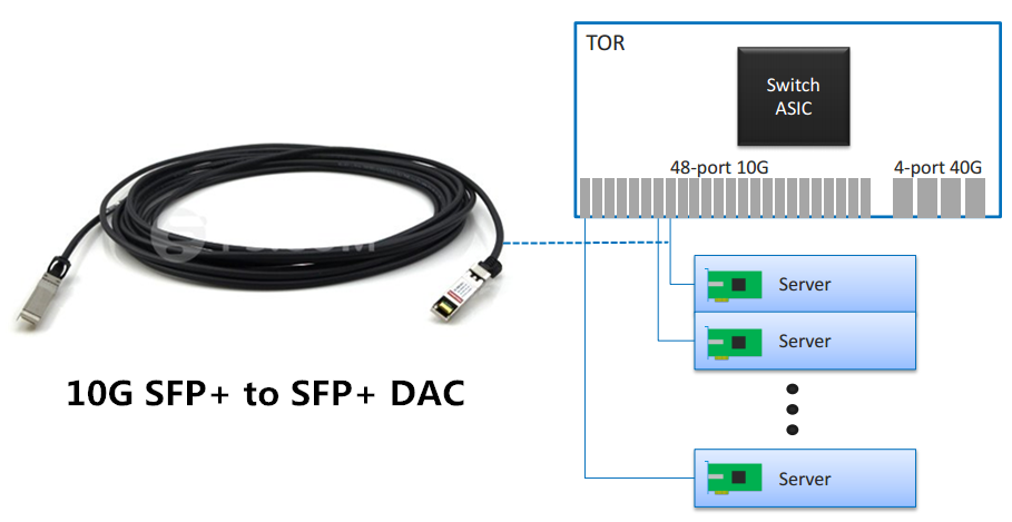
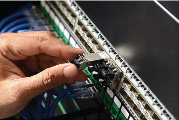
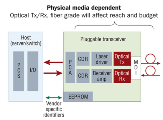
In the 1990s, copper cable was widely used in data center cabling deployment. As time went on, optical fiber cable was added. In fiber switches, it is common to use pluggable transceivers. This is done for a variety of reasons, but one is cost. Even though a transceiver is plugged into a switch, it is part of the OSI Model’s Layer 1, the Physical Layer. Additionally, most of the transceiver is part of the Physical Media Dependent (PMD) portion of Layer 1, as illustrated here. This means that the transceiver and the cable types must match.

transceiver Physical Media Dependent
However, unlike copper, there was never a fixed standard on the connector type or channel distance. Fiber may have many different standards and connector options. With multiple fiber types, multiple operating wavelengths, and multiple connectivity options, the number of solutions seemed limitless. Since the transceiver is physically plugged into the switch, it has always been considered the networking group’s responsibility. “Networking people” are responsible for buying transceivers and “cabling cable” are responsible for buying cabling products, then this causes the problem. Let’s take the following real-life case for example.

Real-life Case and Solution
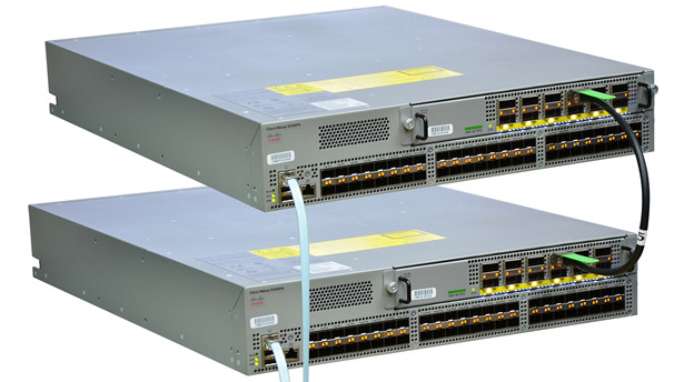
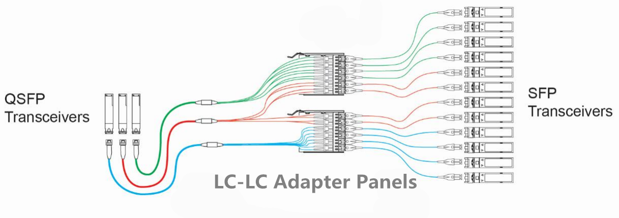
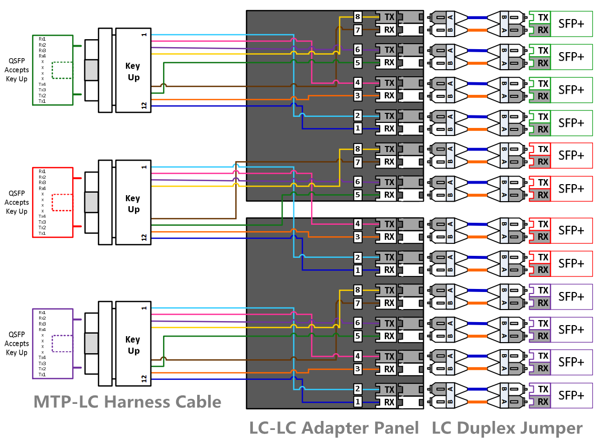
Company A has a data center. Marsha is the facilities manager and is responsible for the data cabling. She has designed a cabling plan that has migrated from 1G into 10G. Anticipating the 40G requirements defined by IEEE 802.3ba (40GBase-SR4), she used a cassette-based platform to allow for the transition from LC connectivity of 10G to the MPO connectivity of 40G. Greg is the network manager. As the migration to 40G switches was about to commence, his hardware vendor recommended that they change to a new unique transceiver solution that used LC connectivity. This appeared to be a great idea because it would mean that Marsha would not have to change any of her connectivity. However, he did not consult with Marsha, because the hardware decisions are his to make. When the 40G switches arrived, Marsha was surprised by the connectivity choice because it limited her power budget. So this division causes the problem.

data center transceiver
Greg needs to have a 40G connection from Rack A to Rack B. From a Layer 2/3 perspective, that is all that matters. He still has the responsibility and complete control to define his needs and select equipment vendors for things like switches, routers, servers, etc. Instead of defining the form of the data rate, he simply specifies the speed. By shifting the single component (pluggable transceiver) from Greg to Marsha, the organization can make its decision much more efficiently. Greg does not have to worry about the variety of fiber and transceiver options, nor the impacts that they have on each other. And Marsha can manage the entire optical link, from transceiver to transceiver, which is all within Layer 1. Her experience with fiber and connectivity options puts her in a better position to determine which transceiver options are the most appropriate.

Conclusion
Looking back, the onset of structured cabling separated the cabling purchasing from the IT hardware purchasing. Looking at present-day and into the future, rapidly increasing data rates, especially in the data center are requiring another shift in the way we conduct business. By redefining the link to include not only cabling and connectivity, but also the transceiver, we put Layer 1 performance in the hands of the people most familiar with it. FS.COM provides a full range of transceivers and matched cabling products with the most cost-effective price. Aimed at offering a high performance-price ratio solutions for you.

25G SFP28 Cable: The Most Economical Option for ToR Server Connection

Share

Have you ever heard of 25G SFP28 cable? It is said to be regarded as the most economical option for ToR server connection. Continue to read and get more details.

What’s 25G SFP28 Cable?

As you may know that 25 Gigabit Ethernet is proposed standard for Ethernet connectivity in a data center environment, developed by IEEE 802.3 task force P802.3by. The IEEE 802.3bj standard then uses technology defined for 100 Gigabit Ethernet implemented as four 25-Gbit/s lanes. These standards define:

  • a single-lane 25 Gbit/s 25GBASE-KR PHY for printed circuit backplanes
  • a single-lane 25 Gbit/s 25GBASE-CR-S PHY for 3 m twin-ax cables (in-rack)
  • a single-lane 25 Gbit/s 25GBASE-CR-L PHY for 5 m twin-ax cables (inter-rack)
  • a single-lane 25 Gbit/s 25GBASE-SR PHY for 100 m OM4 or 70 m OM3 multi-mode optical fiber

According to the above standards, the IEEE CFI is now focused on the SFP28 and QSFP28 direct attach copper twin-ax cables (DACs). SFP28 DAC refers to the 25G DAC cable using the SFP+ form factor, and QSFP28 DAC refers to the 100G DAC cable using the QSFP+ form factor. The maximum transmission distance of these cables is 5 meters.

There are two SFP28 cable types: 25G SFP28 to SFP28 DAC and 100G QSFP28 to four SFP28 breakout DAC. The SFP28 to SFP28 passive copper cable is a high speed, cost-effective 25Gbp/s Ethernet connectivity solution designed to meet the growing needs for higher bandwidth in data centers. The QSFP28 to four SFP28 breakout DAC is used to connect 100G switches to four 25 Gigabit in cabinet or adjacent cabinet servers. Compared to 40G using four 10G lanes and 100G using 10 10G lanes, the 25G SFP28 DAC provides the low-cost copper server connection for Top of Rack (ToR) switches.

To more directly illustrate effectiveness of SFP28 to SFP28 DAC cable and QSFP28 to four SFP28 breakout DAC cable, let’s see a series of pictures displayed below:

Existing 10G Topology
Today’s volume topology for web-scale data centers

  • 48 servers/ToR
  • 3:1 oversubscription
  • Uses low-cost, thin 4-wire SFP+ DAC cable

sfp+ to sfp+ DAC

40G Topology
High-performance, low volume topology

  • Uses bulkier 16-wire QSFP+ DAC cable
  • Max. 24 servers/ToR with 3:1 oversubscription
  • Will transition to 100G

qsfp+ to qsfp+ dac

25G Direct Connect
Same topology as 10G

  • 48 servers/ToR
  • 3:1 oversubscription w/ 100G uplinks, non-blocking w/ 400G
  • Uses 4-wire SFP28 DAC cable

sfp28 to sfp28 dac

Existing 4x10G Topology
Commonly used topology in web-scale data centers

  • Permits non-blocking 10G mesh
  • 40G ports used as 4x10G with QSFP+ to SFP+ breakout cable
  • Same server network interface card (NIC) as 10G

qsfp+ to 4 sfp+ dac

4x25G Breakout
Same topology as 4x10G

  • Permits non-blocking 25G mesh
  • 100G ports used as 4x25G with QSFP28 to SFP28 break-out cable
  • Same server network interface card (NIC) as 25G direct connect

qsfp28 to 4 sfp28 dac

High Density 25G
Increased port switch port density

  • 64 servers in non-blocking architecture
  • 96 servers in a 3:1 oversubscription
  • 24-port 400G ToR
  • 192 servers in non-blocking architecture

100G qsfp28 to 4 sfp28 dac

Related articles:

Taking an In-depth Look at 25G SFP28

25G Vs. 40G Ethernet: Who Is the Winner?

How Far Can 25G Ethernet Go?

The Changing Network Architecture in 25G/100G Data Center

10G SFP+ and 40G QSFP+ Transceivers Cabling Solutions

Share

This article will discuss different connection methods between parallel Quad Small Form-factor Pluggable (QSFP+) transceivers and Small Form-factor Pluggable (SFP+) transceivers. As we know, a 40G QSFP+ transceiver can be either an 8-fiber parallel link or a 2-fiber duplex link. In this document when QSFP is used we will be discussing an 8-fiber parallel link. A SFP+ transceiver is usually an 2-fiber duplex link. According to standard, since QSFP+ is 40G interface, SFP+ is 10G interface, therefore four SFP+ transceiver must be needed to connect to one QSFP+ transceivers to achieve 40G transmission.

40G QSFP+ to 10 SFP+ Direct Connectivity Solutions
When directly connecting a QSFP port to the four corresponding SFP ports, an eight fiber MTP-LC breakout cable is required. The harness will have four LC Duplex connectors and the fibers will be paired in a specific way, assuring the proper polarity is maintained. This type of direct connectivity is only suggested for short distances within a given row or in the same rack/cabinet.

10G SFP+ and 40G QSFP+ direct connection

  • Polarity Drawing for Above Scenario 

Polarity Drawing for Direct Connectivity Solutions

40G QSFP+ to 10 SFP+ Interconnect Solutions
The 40G QSFP+ to 10 SFP+ interconnect solution shown in figure below shows one link with a breakout of the QSFP with the use of an MTP-LC module to four SFP links. A Type-B non-pinned MTP to non-pinned MTP cable is used between MTP-LC modulethe MTP-LC module and QSFP transceiver. The connection to the SFP transceivers is accomplished with Uniboot LC duplexed jumpers. This is a solution that is only recommended for short distances, where the patching takes place within a given row of racks/cabinets. This solution does present some disadvantages which are that ports 5 & 6 of the module are not being used thus reducing the patch panel density. It may also create some confusion when patching occurs since these two ports are dark.

SFP+ QSFP+ Interconnect Solutions

  • Polarity Drawing for Above Scenario Polarity Drawing for 10G SFP+ and 40G QSFP+ Interconnect Solutions

Unlike the patching approach in figure above, the solution shown in figure below has no dark fibers oLC-LC adapter panelr ports. The Type-B jumper is replaced with an eight-fiber harness. The modules are replaced with the LC-LC adapter panel. Using this approach allows full patch panel density that was lost in the previous example. Only two LC-LC adapter panels will be required for every three 8-fiber harnesses. All ports on the LC-LC adapter panels will be used and the connections to the 10GbE ports will be completed with an Uniboot LC duplexed jumper. This solution should also be deployed when there is a short distance between active components (within the same row). Note the LC panel does not support the LC Uniboot connector, only LC Duplex connectors with the triggers removed to avoid clearance issues with the panel cover.

10G 40G Interconnect Solutions

  • Polarity Drawing for Above Scenario 

Polarity Drawing for 10G SFP+ and 40G QSFP+ Solution

Fiberstore (FS.COM) provide all the products mentioned above, including 10G SFP+ transceivers, 40G QSFP+ transceivers, MTP patch cables, MTP-LC harness cable, MTP-LC module and LC-LC adapter panel. All in stock and can be shipped the same day.

Related article: It’s Time to Use MTP Cassettes in Your Network!

How to Achieve 10GB in Your Home Lab Under $70?

Share

A lot of small to medium businesses haven’t made the transition over to 10Gb speeds from the typical 1Gb (at least around where I live), let alone us homelabbers, because of it’s cost. Even with “cheaper” 10GBASE-T switches coming out, like the D-Link DXS-1210-12TC, $1,470 is still a lot more than most of us can convince our wives to let us spend on one. Also, do you have 10Gb NICs on your hosts and NAS/SANs? What about the right cables? These things aren’t cheap.

Inspired by a Reddit post I found over on the /r/homelab subreddit, I decided to try a 10Gb point-to-point connection between my ESXi host (a Dell PowerEdge R520) and my HP ProLiant DL320e that I’m using as my mini-SAN (running Windows Server 2016 TP4). For those that don’t know, a point-to-point connection is a small network between two endpoints or clients, so no switch is needed. My switch (an HP ProCurve 2920) doesn’t have the 10Gb modules needed but I wanted the 10Gb connection between my ESXi host and SAN anyway, so a P2P connection between those two would be perfect.

The NICs talked about in the /r/homelab thread were used HP Mellanox ConnectX-2 10GbE NICs you can find on eBay for SUPER cheap (currently $18.78 each on eBay) connected via this 10GBASE SFP+ cable for $22.94 shipped. I found the NICs to be widely supported but I couldn’t find a lot of information on just how supported they are on the newest operating systems. My host is running ESXi 6 while my ProLiant is running Windows Server 2016 TP4, but for a total of about $65, it was worth the risk of not being supported.

UPDATE: Thanks to Reddit user /u/negabiggz for mentioning that these Mellanox ConnectX-2 NICs do not work under FreeNAS. If you’d still like to create a cheap 10Gb P2P connection in FreeNAS, you can pick up these Chelsio S310E-CR 10Gb NICs on eBayor (shown in figure below) wait till the drivers are natively supported in version 10.1.

Chelsio S310E-CR 10Gb NICs

About a week after placing the orders for the NICs and cable, these two beautiful pieces of used hardware came in along with the SFP+ cable. I immediately took the R520 and ProLiant DL320e out of my rack and got them both easily installed. I fired both machines up and got what every sysadmin and/or homelabber loves to see: both NICs working properly out of the box. Turns out ESXi 6 AND Server 2016 TP4 really do support these cheap, beautiful NICs without the need to install/uninstall/reinstall a ton of different drivers.

maul

This is a screenshot of the 10Gb NIC on my ProLiant right after booting it up and configuring the static IP.

esxi
This is a screenshot of the NIC on my ESXi host after booting it up and getting the other NIC configured on my 2016 TP4 box.

I haven’t done a lot of speed tests to get the official read/write speeds, but I have added the 10Gb NIC to my media downloading VM and transferred a few 720p TV episode files between them and my ProLiant. I tried to take a screenshot of the transfer rate when I copied over a 1GB 720p episode of a TV show I downloaded (legitimately, I swear!), but the screen never came up. I didn’t even get a chance to screenshot it. It was like I just moved the video between folders on the same drive. I also configured an iSCSI connection using the 10Gb link and performance so far has been great.

So there you have it. An awesome 10Gb speed on your homelab all for under $70. Thanks to the /r/homelab community for the idea and for suggesting the hardware, especially for those of us that didn’t want to convince our wives why we need to spend hundreds of dollars so we can transfer files using a puny 1Gb connection.

Source: https://thatservernerd.com/2016/02/23/10gb-in-your-homelab-for-under-70