There was a time that cable products specifically associated with hardware OEMs. If a company was buying or using one of these vendors’ products, the matching cables also had to be used. Therefore, whoever was responsible for managing the hardware was also responsible for the cabling used to connect the devices together. Then, the structured cabling industry replaced this. The cabling infrastructure is now viewed as an independent asset separate from the IT hardware. This has allowed companies to make purchasing decisions for IT and cabling without the concern of each other. But this may be a problem. To understand the problem, let’s understand the LAN network operation principles first.

The OSI Model of LAN Network
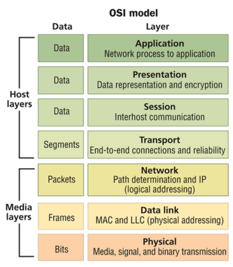
As we know, the operation of local area networking (LAN) was defined with the Open Systems Interconnection Reference Model (OSI Model). The OSI Model defined seven layers of operation. By using the model, the industry could develop networking functions in a modular fashion and still ensure interoperability. The bottom of the stack is Layer 1, the Physical Layer. Layer 1 includes the cabling that is used to connect the various pieces of equipment together so that the data can be transported. The next step up on the stack is Layer 2, the Data Link Layer. Layer 2 provides for addressing and switching, so that the data can be sent to the appropriate destination. Layer 3 is the Network Layer, where data can be routed to another network. Layers 4 through 7 deal with software implementations.

The OSI Model meant that an end-user could purchase software (Layer 7) and expect it to work on multiple vendors’ hardware (Layer 2). And the hardware could be connected using multiple vendors (Layer 1). Structured cabling now had a home within Layer 1. Then this module leads to division of responsibility, for cabling versus network design specifications. The end-user ended up having “cabling people” and “networking people” on their staff. Each group of people used their own set of vendors and supply chains to specify and source their materials. And they each only needed a very basic understanding of what the other people were doing. This system has worked very well for the enterprise LAN. So what’s the problem?
What Is the Problem?
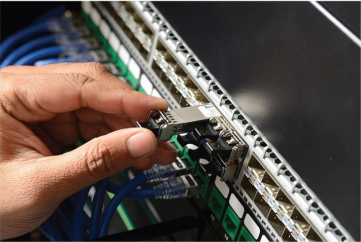
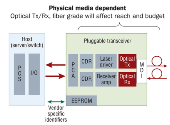
In the 1990s, copper cable was widely used in data center cabling deployment. As time went on, optical fiber cable was added. In fiber switches, it is common to use pluggable transceivers. This is done for a variety of reasons, but one is cost. Even though a transceiver is plugged into a switch, it is part of the OSI Model’s Layer 1, the Physical Layer. Additionally, most of the transceiver is part of the Physical Media Dependent (PMD) portion of Layer 1, as illustrated here. This means that the transceiver and the cable types must match.

However, unlike copper, there was never a fixed standard on the connector type or channel distance. Fiber may have many different standards and connector options. With multiple fiber types, multiple operating wavelengths, and multiple connectivity options, the number of solutions seemed limitless. Since the transceiver is physically plugged into the switch, it has always been considered the networking group’s responsibility. “Networking people” are responsible for buying transceivers and “cabling cable” are responsible for buying cabling products, then this causes the problem. Let’s take the following real-life case for example.
Real-life Case and Solution
Company A has a data center. Marsha is the facilities manager and is responsible for the data cabling. She has designed a cabling plan that has migrated from 1G into 10G. Anticipating the 40G requirements defined by IEEE 802.3ba (40GBase-SR4), she used a cassette-based platform to allow for the transition from LC connectivity of 10G to the MPO connectivity of 40G. Greg is the network manager. As the migration to 40G switches was about to commence, his hardware vendor recommended that they change to a new unique transceiver solution that used LC connectivity. This appeared to be a great idea because it would mean that Marsha would not have to change any of her connectivity. However, he did not consult with Marsha, because the hardware decisions are his to make. When the 40G switches arrived, Marsha was surprised by the connectivity choice because it limited her power budget. So this division causes the problem.

Greg needs to have a 40G connection from Rack A to Rack B. From a Layer 2/3 perspective, that is all that matters. He still has the responsibility and complete control to define his needs and select equipment vendors for things like switches, routers, servers, etc. Instead of defining the form of the data rate, he simply specifies the speed. By shifting the single component (pluggable transceiver) from Greg to Marsha, the organization can make its decision much more efficiently. Greg does not have to worry about the variety of fiber and transceiver options, nor the impacts that they have on each other. And Marsha can manage the entire optical link, from transceiver to transceiver, which is all within Layer 1. Her experience with fiber and connectivity options puts her in a better position to determine which transceiver options are the most appropriate.
Conclusion
Looking back, the onset of structured cabling separated the cabling purchasing from the IT hardware purchasing. Looking at present-day and into the future, rapidly increasing data rates, especially in the data center are requiring another shift in the way we conduct business. By redefining the link to include not only cabling and connectivity, but also the transceiver, we put Layer 1 performance in the hands of the people most familiar with it. FS.COM provides a full range of transceivers and matched cabling products with the most cost-effective price. Aimed at offering a high performance-price ratio solutions for you.
