Category Archives: Cabling Solutions

Why Demand for Ultra High Density Fiber Optic Enclosures?

Share

Increased demand for data to support streaming media and the increased use of mobile broadband communications has resulted in dramatic advances in network switching infrastructure over the past 10 years. Furthermore, this demand is expected to continue at a record pace. Since the transition from copper to fiber as the standard for high-performance data communications and the number of fibers used to support emerging standards, such as 100GBit/s Ethernet, for the individual connection has increased, to choose higher density fiber optic enclosures is certainly innate.

Currently, network switching products are available with port line cards that use more than 1,000 OM3 fiber and OM4 fibers per chassis switch for 10G duplex fiber applications. Future 40/100Gb switches are projected to use more than 4,000 fibers per chassis where parallel optics is used. These high fiber count requirements demand high-density cable and hardware solutions that will reduce the overall footprint and simplify cable management and connections to the electronics.

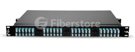
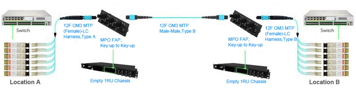
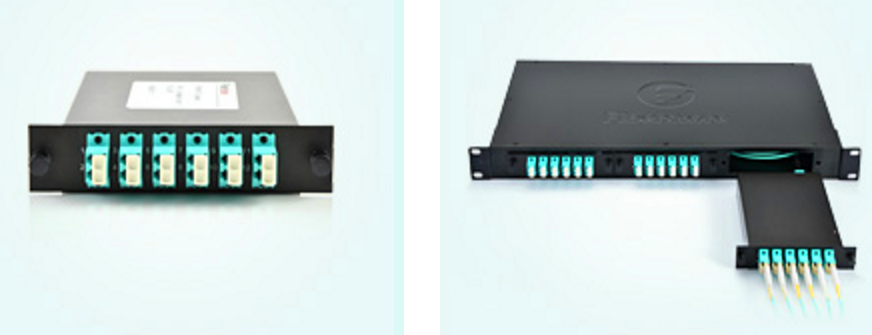
Fiberstore’s new FMT1-4FAP-LCDX series product allows customers to migrate from a standard 2U fiber enclosure that will house 3 adapter panels for a maximum of 72 LC connectors to our new 96 ports fiber optic enclosures that will hold 4 adapter panels in a 1U space allowing a maximum of 96 LC connectors! This gives users 33% (or 24 more) more LC connections in a 1U enclosure versus a 2U enclosure.

96 Ports Fiber Optic Enclosure

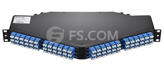
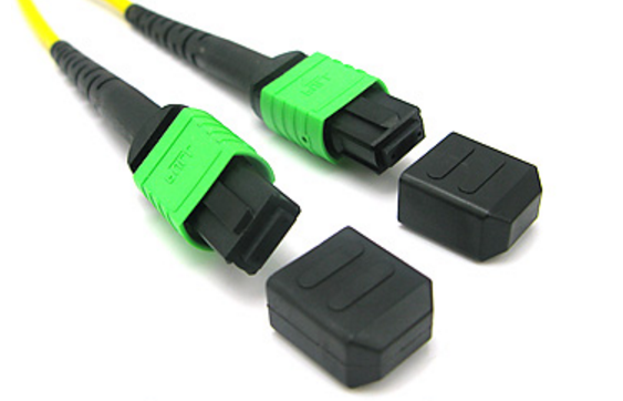
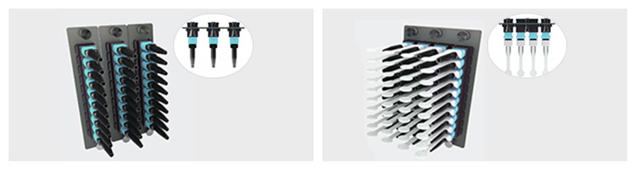
Besides, you can get more density by utilizing our MPO/MTP to LC cassette module. Our HDSM-12MTP/MPO rack mountable MTP cassette is loaded with 72 LC duplex connectors, giving it 144 ports total within 1U of rack space. And this 1U enclosures can be mounted vertically so you can match every blade in the switch to each enclosure. This high-density MTP cassette is constructed of light weight, yet durable, rolled steel. The shallow depth of the Ultra Panel makes it suitable for copper racking systems or telecommunication rack infrastructure.

144 Ports Fiber Optic Enclosure

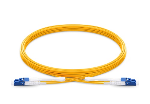
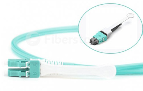
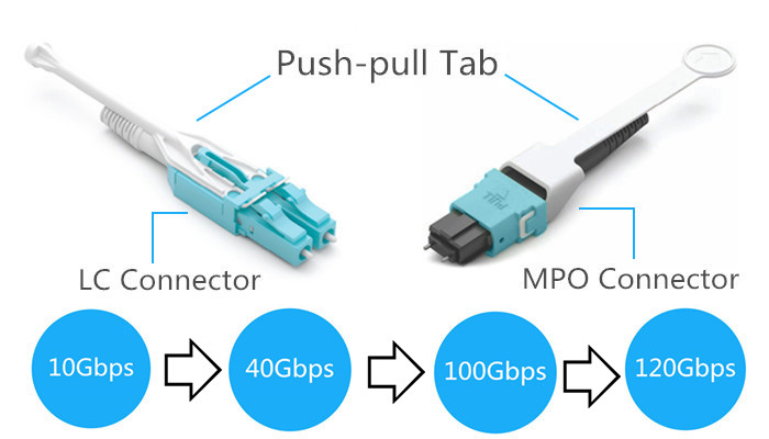
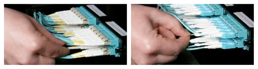
With the rise in demand for higher bandwidth and faster download speeds, FS.COM high-density fiber optic enclosures were designed to keep pace with these requirements. In addition, both of these unique fiber optic enclosure lines offer installers easy terminations, and performance-driven connectivity. Couple that with FS.COM’s proven fiber optic cable, in particular, our HD push-pull tab patch cables, customers can expect an exceptional solution to fit their high-density needs.

Why Do You Need MTP Pre-Terminated Fiber Solutions?

Share

Today’s modern data center proposition continues to promote the hot topics around consolidation, reduced operating expense, flexibility, scalability and of course being as ‘Green’ as possible along the way. That sounds simple, but when you start to achieve all of the above, maybe difficult than you imagine. Recently, more and more mission critical enterprise networks are considering the need for multiple fibers in a high density, modular and pre-terminated solution. Why are they become so popular? And do you also consider this solution for your network?

Some Changes Occurred in Panel to Panel Links
We have seen panel to panel links, both copper and fiber being installed for many years. These tend to be mainly in data centres, linking up racks, and therefore providing easy moves and changes within local patching fields. But, the trouble is these fibers are terminated and then fixed permanently in to place. In the past, a fiber installation would have involved a good amount of forward thinking, ensuring that the planned lengths were precise as there would be little movement to rectify any mistakes. This would result in a costly installation. Therefore, it’s clear that high speed enterprise networks are already demanding and installing multiple fibers MTP solution, meaning selecting that right easy and expandable fiber infrastructure choice from the offset is of vital importance.

Pre-Terminated MTP Connection Becomes the Hottest Topic
When it comes down to fiber it has to be the pre-terminated MTP connections, providing new advancing technologies that provide multiple fibers in a very small and modular footprint. MTP type connectors, also referred to as MPO, supplying you with a single trunk cable of either 12 or 24 cores. All in all, not much thicker than a standard fiber patch lead, so greatly reduced in size from previous pre-terminated fiber cable installations. However, already being requested are larger cores of 36, 48, 72, 96 or even 144 – but do keep in mind that these will be thicker in construction and could be made of multiple cores on a number of separate cables.

12 24 MTP MPO connector

Where Could Pre-Terminated MTP Solution Be Used?
The MTP to MTP fiber cassettes suit various environments, applications and budgets. Primarily, data centres, DR-Co locations, FCoE SAN’s, links between floors/risers and larger communication rooms. Basically, for anyone that needs to quickly create a 10 Gigabit performance fiber network backbone. All of these demand, and would ultimately benefit, from the uncompromised performance, density and scalability that MTP solutions can provide. Additional to the MTP to MTP cassette links, we are also seeing an increased demand for ‘last metre’ fan out cables. For example, 12x LC connections to a single MTP adapter, being used for direct 40 Gigabit equipment links. With the ever increasing need for more bandwidth and virtualisation of application 40Gbp’s speeds are already being installed in data centers.

MTP Pre-Terminated Fiber Solution

How Does It All Stack Up?
Supplied as part of the MTP solution is a 1U rack mountable fiber enclosure, so the installation is extremely easy. Each 1U enclosure will hold 3 cassettes and at the back of each cassette you can then access the MTP trunk cable male socket(s). The more cassettes you purchase the more 1U trays are supplied. You will then find at the front of multimode or single-mode cassettes are the legacy LC fiber connections, in either a 6 or 12 duplex (12 or 24 Core), to link back to the active network hardware or existing patch panels. Minimal time is required for the installation, with no need for onsite fiber termination and better still no out of hours working, allowing you to experience the highest performance from your network.

MTP cassette

If you would like any further information around our easy and expandable MTP fiber solution then please do get in touch with us at sales@fs.com or visit our website at www.fs.com. Thanks for reading and I hope this article has been a useful introduction to MTP pre-terminated fiber solution.

Do You Know about Push-Pull Tab Fiber Patch Cables?

Share

More and more data centers are upgrading to 40G and beyond, which adds more floor space is an expensive, disruptive and sometimes un-affordable solution. Therefore, we should use high-density products to solve this problem. Then push-pull TAB fiber patch cables were conceived. This high-density patch cable provides improved accessibility, reduced installation costs and outstanding performance for today’s demanding high-density data center applications. In this article, some knowledge of push-pull TAB fiber patch cables will be provided.

Introduction to Push-Pull Tab Patch Cables
Push-Pull Tab Patch CablePush-pull TAB fiber patch cable is a new patch cord with a special “pull” tab design that can help to solve the problems of finger access in high-density cabling. It has the same components and internal-structure as the traditional patch cords, except a tab attached to the connector used for pushing or pulling the whole connector. With this special design, technicians can finish the installing and removing procedures with only one hand and no additional tools are needed. At present, this high-density push-pull TAB fiber patch cable, with either MPO or LC connector, is widely used in 40G and 100G network cabling.

Types of Push-Pull Tab Patch Cables
There are mainly two kinds of push-pull TAB fiber patch cables in the market: LC-HD TAB fiber patch cables and MPO-HD TAB fiber patch cables. The LC-HD TAB fiber patch cable is designed for the LC-HD switchable& movable connector. And its slim uni-boot design saves much space and makes cables more easily to be managed. MPO-HD TAB fiber patch cables can greatly simplify the use of MPO connectivity when manual access to the release slider and rear portion of the connector is restricted. In this way, easy insertion and extraction of MPO patch cords can be achieved.

push-pull-tab-patch-cords_

Advantages of Using Push-Pull Tab Patch Cables
Though traditional patch cables are popular in the data center, the push-pull TAB patch cables have many unique advantages.

  • Easy to Release Patch Cord

In high-density environment such as 48-port 1U patch panels, inserting and disconnecting patch cords can be challenging for technicians. The flexible pull-tab of the patch cable allows for the connector to be disengaged easily from loaded panels without the need for special tools. In fact, a gentle pull on the tab may disengage the connector from extremely dense fiber patch panels. Furthermore, labeling is also available on the pull-tab so that each cable can be quickly identified.

high-density Push-Pull Tab Patch Cable

  • Higher Flexibility and Adjustabilityfie

Push-pull patch cords are available in various specifications which can connect different generation of devices from 10Gb/s to 120Gbp/s or more. It provides safe and easy push and pull of the specific connector without affecting the other connectors around it. What’s more, high-density and ease of installation provide a low initial investment cost. All these benefits provide a high return on investment.

  • Space Saving

The traditional connectors often require a small vertical space above and below the adapters. While the low profile push-pull TAB patch cable, together with its pull tab, allow adapters to be stacked with absolutely no vertical space (as in the following figure).

Push-Pull Tab Patch Cables

Conclusion
We started with 1G switches. Those switches became 10G. Recently we’ve seen the trend of 40G. In the future, those switches will become 100G and even 120G. It has been proved that push-pull tab patch cords can support high durability and flexibility which fit the connection between devices of different data rate. Fiberstore offers a wide range of push-pull TAB patch cables that will help free up space.We supply simplex&duplex LC-HD patch cords, 12&24 fibers MPO-HD patch cords, MPO-LC harness cables, providing low-loss performance for multi-mode and single mode high speed networks and improving network performance.

40GBASE-SR4/CSR4 QSFP+ Transceiver Direct Connection Cabling

Share

As we all know, the standard specifies MPO as a connector to the 40GBASE-SR4/CSR4 QSFP+ transceiver. To connect a QSFP+ to QSFP+, we usually use a MTP 12-fiber trunk cable. In the 40GBASE-SR transmission, there are eight fibers associated with the channel—four fibers for the TX signal and four fibers for the RX signal. Therefore only 8 of the 12 fibers are used, where the remaining four are not used, and can optionally be not present in the cable. So we can also choose a MTP 8-fiber trunk cable for connectivity. This article explains 40G QSFP+ SR4/CSR4 transceiver to 40G QSFP+ SR4/CSR4 transceiver cabling selections.

How to Choose Right  MTP Trunk Cables? 
In addition to using a MTP 8-fiber trunk cable or MTP 12-fiber trunk cable, there are a number of other factors also needed to be considered when to choose a right MTP trunk cable for 40G QSFP+ SR4/CSR4 transceiver connectivity.

  • Use single-mode or multimode MTP trunk cable?

In the market, both single-mode and multiode MTP trunk cable are available. Which one should I use? According to 40GBASE-SR4 standards, 40G QSFP+ SR4 transceiver supports link lengths of 100 meters and 150 meters, respectively, on laser-optimized OM3 and OM4 multimode fibers. Therefore, to connect a 40G QSFP+ SR4  to 40G QSFP+ SR4, we should choose OM3 or OM4 multimode MTP trunk cables.

  • MTP trunk cable polarity selection: A, B or C?

In terms of MTP trunk cable, there are three kinds of polarity options (A, B and C). Which one to choose? In fact, according to the IEEE 40GBASE-SR4 specifications, we must select a type B MTP 8-fiber or MTP 12-fiber trunk cable. The type B trunk cable has opposing connectors with both keys oriented facing up, however the fiber positions are reversed at each end i.e. the fiber at position 1 at one end is connected to position 12 in the connector at the opposing end.

Type-B-MTP-trunk-cable

  • Choose male or female MTP trunk cable?

In terms of a MPO connector, it is divided into male and female types. They ensure that the adapter holds the connector with the correct ends aligned with each other. A MPO trunk cable usually has two MPO connector on each side. Therefore, MTP trunk cables are available in male–male and female–female two versions. According to IEEE standards, MPO optics in a 40G QSFP+ SR4 transceiver are always male connectors, and therefore will always accept female MPO connectors. So if we want to connect a 40G QSFP+ SR4 transceiver  to a 40G QSFP+ SR4 transceiver successfully, we must choose a female–female MTP trunk cable.

40G QSFP+ SR4/CSR4 to 40G QSFP+ SR4/CSR4 Cabling Selections
In order to satisfy different cabling requirement, we may choose different cabling methods. And different cabling methods call for many different cabling infrastructure. Following are four type common cabling methods to connect a 40GBASE-SR4/CSR4 QSFP+ to 40GBASE-SR4/CSR4 QSFP+.

  • Direct connection for 40 Gigabit Ethernet parallel optic transceiver

When directly connecting one QSFP+ MPO/MTP interface transceiver to another, a Type-B female MPO/MTP to female MPO/MTP cable is required. This type of direct connectivity is only suggested for short distances within a given row of racks/cabinets. Following picture shows two QSFP+ transceivers being connected with a MTP female cable.

solutions_40G_pic01

Item Number FS Correlative Product Description FS Part Number
1 40GBASE-SR4 QSFP+, 850nm, 150m, MMF, MPO interface QSFP-SR4-40G
2 12 Fibers OM4, 12 Strands MTP Trunk Cable, Female to Female, Type B Polarity ( MTP/ MPO, OM4/ OM3 optional. Various lengths available) FS12OM4-2MTP-FF-B
  • 40GbE direct interconnect with MTP trunk cable and patch panel

For distances less than 400 meters, the use of FS MPO/MTP multi-mode fiber cabling is generally the preferred cabling method. The next solution is similar to the previous, but instead of using a 12-fiber jumper directly, the MPO/MTP adapter panel is interconnected. Following picture shows the distribution switch and FS optics and cabling options with corresponding item details for a QSFP+ to QSFP+ multi-mode interconnection.

solutions_40G_pic02

Item Number FS Correlative Product Description FS Part Number
1 40GBASE-SR4 QSFP+, 850nm, 150m, MMF, MPO interface QSFP-SR4-40G
2 12 Fibers OM4, 12 Strands MTP Trunk Cable, Female to Female, Type B Polarity ( MTP/ MPO, OM4/ OM3 optional. Various lengths available) FS12OM4-2MTP-FF-B
3 12 Ports MTP/MPO Fiber Adapter Panel, key-up to key-up FAP-HV-12MTPUUD
  • 10Gig migrate to 40GbE by interconnecting MTP LGX cassette and MTP trunk cable

Following picture shows one link with a breakout of the QSFP+ with the use of an MPO/MTP LGX cassette to four 10G SFP+ links. A Type-B female MPO/MTP to Female MPO/MTP assembly is used between the MPO/MTP LGX cassette and 40GbE transceiver. The connections to the SFP+ transceivers is accomplished with OM3/OM4 Uniboot LC duplex fiber patch cables.

solutions_40G_pic03

Item Number FS Correlative Product Description FS Part Number
1 10GBASE-SR SFP+, 850nm 300m, MMF, LC duplex SFP-10GSR-85
2 LC-LC Duplex 10G OM4, MMF Patch Cable OM4-LC-LC-DX-FS
3 12 Fibers OM4, LGX – MTP Cassette, MTP(male) to LC FS12OM4-LGX-2MTP-LC
4 MTP/MPO LGX Cassettes 1U/4U 19” Rack Mount FS-1RU-MX
5 12 Fibers OM4, 12 Strands MTP Trunk Cable, Female to Female, Type B Polarity ( MTP/ MPO, OM4/ OM3 optional. Various lengths available) FS12OM4-2MTP-FF-B
6 10GBASE-SR SFP+, 850nm 300m, MMF, LC duplex SFP-10GSR-85
  • 10Gig migrate to 40GbE by interconnecting MTP harness cable and MTP trunk cable

Sometimes, create a simple, cost-effective migration path by installing a structured cabling system that can support your future 40GbE networking needs. Following picture uses the 8-fiber harness as shown in the diagram to connect to 10G SFP+s. This approach allows for an easy upgrade path moving from 10Gig to 40GbE connectivity.

solutions_40G_pic04

Item Number FS Correlative Product Description FS Part Number
1 10GBASE-SR SFP+, 850nm 300m, MMF, LC duplex SFP-10GSR-85
2 8 Fibers OM4, 12 Strands MTP Harness Cable, MTP to LC, Type B Polarity ( MTP/ MPO, OM4/ OM3 optional. Various lengths available) OM4-LC-LC-DX-FS
3 12 Ports MTP/MPO Fiber Adapter Panel, key-up to key-up FAP-HV-12MTPUUD
4 Empty 1RU/4RU Rack Mount Fiber Patch Panel FMT1-E-FS
5 12 Fibers OM4, 12 Strands MTP Trunk Cable, Female to Female, Type B Polarity ( MTP/ MPO, OM4/ OM3 optional. Various lengths available) FS12OM4-2MTP-FF-B
6 40GBASE-SR4 QSFP+, 850nm, 150m, MMF, MPO interface QSFP-SR4-40G

Fiberstore provides wide brand compatible 40G QSFP+ SR4 transceivers and all kinds of MTP cables. Each fiber optic transceiver has been tested to ensure its compatibility and interoperability. Please rest assured to buy. For more information or quotation, please contact us via sales@fs.com.

Related Article: 40G Transceiver Module: QSFP+ Module And CFP Module

Which SFP Fiber Cable Should I Choose for My Optical Transceiver?

Share

SFP fiber cable and fiber optic transceiver have become more and more important in fiber optic data transmission, especially in data transmission between the switches and equipment. But with so many different kinds of SFP fiber cables available in the market, which one is suitable for may optical transceiers? This article may on this issue to provide some solutions. Before starting this topic, it is necessary for us to review the basic knowledge of the fiber optic transceiver and fiber optic cable.

Fiber Optic Transceiver Overview
Fiber Optic Transceiver is a self-contained component that can both transmit and receive. Usually, it is inserted in devices such as switches, routers or network interface cards which provide one or more transceiver module slot. There are many optical transceivers types, such as SFP+ transceiver, X2 transceiver, XENPAK transceiver, XFP transceiver, SFP (Mini GBIC) transceiver, GBIC transceiver and so on.

Fiber Optic Transceiver

Fiber Optic Patch Cable Overview
Fiber optic patch cable, also known as fiber jumper or fiber optic patch cord. It is composed of a fiber optic cable terminated with different connectors on the ends. Fiber optic patch cables are used in two major application areas: computer work station to outlet and patch panels or optical cross connect distribution center. According to fiber cable mode, cable structure or connector types etc., fiber patch cable can be divided into different types.

SFP Fiber Cable

1.Single-mode and Multimode SFP fiber Cable
According cable mode, patch cables can be divided into single-mode and multimode fiber patch cable. The word mode means the transmitting mode of the fiber optic light in the fiber optic cable core. Single-mode patch cables are with 9/125 fiber glass and are yellow jacket color, while multimode patch cables are with OM1 62.5/125 or OM2 50/125 fiber glass and are orange color. In addition, there is 10G OM3 and OM4 multimode patch cables which cable jacket are usually aqua.

2.Simplex and Duplex SFP fiber Cable
Simplex fiber patch cable is consist of single fiber core, while duplex fiber patch cable is consist of two fiber cores and can be either singlemode or multimode. Additionally, there is also ribbon fan-out cable assembly (ie. one end is ribbon fiber with multi fibers and one ribbon fiber connector such as MTP connector (12 fibers), the other end is multi simplex fiber cables with connectors such as ST, SC, LC, etc.).

3.LC, SC, ST, FC, MT-RJ, E2000, MU and MPO/MTP Patch Cable
Fiber optic patch cable can be also classified by the types of fiber optic connector. For example, LC fiber optic patch cable is named as it is with LC connector. Similarly, there are SC, ST, FC, MT-RJ, E2000, MU and MPO/MTP fiber optic patch cables. What’s more, there are PC, UPC, APC type fiber patch cords, which are differentiated from the polish of fiber connectors.

Which SFP fiber Cable Should I Choose for My Fiber Optic Transceivers?
Now, I will take the Cisco fiber optic transceiver as an example to discuss this topic. For example, we need to choose a right patch cable to connect Cisco fiber optic transceiver SFP-10G-SR and X2-10GB-SR. Which patch cable to use? According to “Cisco 10-Gigabit Ethernet Transceiver Modules Compatibility Matrix”, we may know that SFP-10G-SR is the 10GBASE-SR SFP+ transceiver module for MMF, 850-nm wavelength, LC duplex connector. And X2-10GB-SR is the 10GBASE-SR X2 transceiver module for MMF, 850-nm wavelength, SC duplex connector. Obviously, this two knids of optica trancseivers are both for MMF, so we should choose a multimode patch cable. Besides, we know X2-10GB-SR is designed for SC duplex connector and the SFP-10G-SR is designed for duplex LC connector, so we should use a patch cable with SC-LC duplex connector.

Which Patch Cable Should I Choose for My Fiber Optic Transceivers

The Most Common Used SFP fiber Cable Selection
In the way mentioned above, you could choose right fiber patch cable for your other transceiver modules. Keep in mind that if your transceiver modules are not Cisco’s, you need to ask your brand supplier to get the corresponding compatibility matrix. In fact, in terms of a same kind of optical transceiver, different supplier may provide the transceiver with different specifications. Here I may list the most common used patch cables selection. Hope to give you smoe reference.

Fiber optic patch cable Applicable fiber optic transceiver connection
LC-LC Simplex 9/125 Single-mode Fiber Patch Cable 1.25Gbps 1310nmTX/1490nmRX BiDi SFP

10GBASE 1270nmTX/1330nmRX BiDi SFP+

LC-LC Duplex 9/125 Single-mode Fiber Patch Cable 1000Base-LX/LH 1310nm 10km LC SMF SFP
LC-SC Duplex 9/125 Single-mode Fiber Patch Cable Cisco X2-10GB-LR , Cisco XENPAK-10GB-LR and Cisco SFP-10G-LR
SC-LC Duplex 10G OM4 50/125 Multimode Fiber Patch Cable Cisco XENPAK-10GB-SR , Cisco X2-10GB-SR and Cisco SFP-10G-SR
LC-LC Duplex OM1 62.5/125 Multimode Fiber Patch Cable 100Base-FX 2km 1310nm MMF LC SFP
LC-LC Duplex OM2 50/125 Multimode Fiber Patch Cable 1000Base-SX 850nm 550m LC MMF SFP
LC-LC Duplex 10G OM3 50/125 Multimode Fiber Patch Cable 10GBASE-SR 850nm 300m Multi-Mode SFP+
LC-LC Duplex 10G OM4 50/125 Multimode Fiber Patch Cable Cisco SFP-10G-SR Compatible 10GBASE-SR SFP+

Related Article: Differences Between SFP, BiDi SFP and Compact SFP

Related Article: Cisco SFP-10G-SR: All You Need to Know

What Kind of Single Mode Fiber Should You Choose?

Share

As we all know, multimode fiber is usually divided into OM1, OM2, OM3 and OM4. Then how about single mode fiber? In fact, the types of single mode fiber seem much more complex than multimode fiber. There are two primary sources of specification of single mode optical fiber. One is the ITU-T G.65x series, and the other is IEC 60793-2-50 (published as BS EN 60793-2-50). Rather than refer to both ITU-T and IEC terminology, I’ll only stick to the simpler ITU-T G.65x in this article. There are 19 different single mode optical fiber specifications defined by the ITU-T.

Name Type
ITU-T G.652 ITU-T G.652.A, ITU-T G.652.B, ITU-T G.652.C, ITU-T G.652.D
ITU-T G.653 ITU-T G.653.A, ITU-T G.653.B
ITU-T G.654 ITU-T G.654.A, ITU-T G.654.B, ITU-T G.654.C
ITU-T G.655 ITU-T G.655.A, ITU-T G.655.B, ITU-T G.655.C, ITU-T G.655.D, ITU-T G.655.E
ITU-T G.656 ITU-T G.656
ITU-T G.657 ITU-T G.657.A, ITU-T G.657.B, ITU-T G.657.C, ITU-T G.657.D

Each type has its own area of application and the evolution of these optical fiber specifications reflects the evolution of transmission system technology from the earliest installation of single mode optical fiber through to the present day. Choosing the right one for your project can be vital in terms of performance, cost, reliability and safety. In this post, I may explain a bit more about the differences between the specifications of the G.65x series of single mode optical fiber families. Hope to help you make the right decision.

G.652
The ITU-T G.652 fiber is also known as standard SMF (single mode fiber) and is the most commonly deployed fiber. It comes in four variants (A, B, C, D). A and B have a water peak. C and D eliminate the water peak for full spectrum operation. The G.652.A and G.652.B fibers are designed to have a zero-dispersion wavelength near 1310 nm, therefore they are optimized for operation in the 1310-nm band. They can also operate in the 1550-nm band, but it is not optimized for this region due to the high dispersion. These optical fibers are usually used within LAN, MAN and access network systems. The more recent variants (G.652.C and G.652.D) feature a reduced water peak that allows them to be used in the wavelength region between 1310 nm and 1550 nm supporting Coarse Wavelength Division Multiplexed (CWDM) transmission.

G.652 

G.653
G.653 single mode fiber was developed to address this conflict between best bandwidth at one wavelength and lowest loss at another. It uses a more complex structure in the core region and a very small core area, and the wavelength of zero chromatic dispersion was shifted up to 1550 nm to coincide with the lowest losses in the fiber. Therefore, G.653 fiber is also called dispersion-shifted fiber (DSF). G.653 has a reduced core size, which is optimized for long-haul single mode transmission systems using erbium-doped fiber amplifiers (EDFA). However, its high power concentration in the fiber core may generate nonlinear effects. One of the most troublesome, four-wave mixing (FWM), occurs in a Dense Wavelength Division Multiplexed (CWDM) system with zero chromatic dispersion, causing unacceptable crosstalk and interference between channels.

G.653

G.654
The G.654 specifications entitled “characteristics of a cut-off shifted single mode optical fiber and cable.” It uses a larger core size made from pure silica to achieve the same long-haul performance with low attenuation in the 1550-nm band. It usually also has high chromatic dispersion at 1550 nm, but is not designed to operate at 1310 nm at all. G.654 fiber can handle higher power levels between 1500 nm and 1600 nm, which is mainly designed for extended long-haul undersea applications.

G.655
G.655 is known as non-zero dispersion-shifted fiber (NZDSF). It has a small, controlled amount of chromatic dispersion in the C-band (1530-1560 nm), where amplifiers work best, and has a larger core area than G.653 fiber. NZDSF fiber overcomes problems associated with four-wave mixing and other nonlinear effects by moving the zero-dispersion wavelength outside the 1550-nm operating window. There are two types of NZDSF, known as (-D)NZDSF and (+D)NZDSF. They have respectively a negative and positive slope versus wavelength. The following picture depicts the dispersion properties of the four main single mode fiber types. The typical chromatic dispersion of a G.652 compliant fiber is 17ps/nm/km. G.655 fibers were mainly used to support long-haul systems that use DWDM transmission.

G.655

G.656
As well as fibers that work well across a range of wavelengths, some are designed to work best at specific wavelengths. This is the G.656, which is also called Medium Dispersion Fiber (MDF). It is designed for local access and long haul fiber that performs well at 1460 nm and 1625 nm. This kind of fiber was developed to support long-haul systems that use CWDM and DWDM transmission over the specified wavelength range. And at the same time, it allows the easier deployment of CWDM in metropolitan areas, and increase the capacity of fiber in DWDM systems.

G.657
G.657 single mode fiberG.657 optical fibers are intended to be compatible with the G.652 optical fibers but have differing bend sensitivity performance. It is designed to allow fibers to bend, without affecting performance. This is achieved through an optical trench that reflects stray light back into the core, rather than it being lost in the cladding, enabling greater bending of the fiber. As we all know, in cable TV and FTTH industries, it is hard to control bend radius in the field. G.657 is the latest standard for FTTH applications, and, along with G.652 is the most commonly used in last drop fiber networks.

From the passage above, we know that different kind of single mode fiber has different application. Since G.657 is compatible with the G.652, some planners and installers are usually likely to come across them. In fact, G657 has a larger bend radius than G.652, which is especially suitable for FTTH applications. And due to problems of G.643 being used in WDM system, it is now rarely deployed, being superseded by G.655. G.654 is mainly used in subsea application. According to this passage, I hope you have a clear understanding of these single mode fibers, which may help you make the right decision.

Related Article: https://community.fs.com/blog/what-kind-of-single-mode-fiber-should-you-choose.html

Does Bend Insensitive Multimode Fiber Make Sense?

Share

Bend Insensitive MMFAs we all know, when optical fiber exceeds a certain bend radius, some amount of light can be lost, causing signal loss. This can happen during installation or anytime during fiber handling, and is often a concern within the tight spaces of high-density fiber patching areas in the data center. Today, a bend insensitive multimode fiber (BIMMF) was introduced, which can withstand tight bends, or even kinks, without suffering significant loss or any loss in a lot of cases. However, there are no standards around BIMMF and there are concerns about compatibility between BIMMF and traditional fibers. Besides, there are also questions around bandwidth measurements in the factory and actual performance in the fields. So, does BIMMF really make sense? Let’s find the answer together.

What Is Bend Insensitive Multimode Fiber?
Bend insensitive multimode fiber, first introduced in 2009, is quickly becoming the fiber of choice for high-performance enterprise LANs and data centers. With the introduction of BIMMF, installers were finally able to deploy fiber networks without fear of over-bending the fiber and degrading performance. Compared with standard fibers, BIMMF has a specially engineered optical “trench” added between the core and cladding. This trench contains the propagating modes within the fiber core, even in an extreme bend. It retains more of the light that would have escaped the core of a traditional multimode fiber. BIMMF enables more compact fiber management systems and to improve space utilization in modules, enclosures, cabinets and patch fields. Today, BIMMF is widely deployed in data centers and much has been published about its design and benefits.

BIMMF

Is BIMMF Compatible with Non-BIMMF?
The preceding core diameter and numerical aperture discussions revealed that there are mode-field shape differences between traditional MMF and BIMMF. These differences fundamentally reduce the match between these fiber types and can lead to elevated connection loss. However, modeling and testing on BIMMF has shown that an optimized BIMMF is backward compatible and can be mixed with non-BIMMF without inducing exconnection losscess loss. There is also evidence that connector incompatibility and fiber geometry differences (core diameter) may cause direction dependence regardless of fiber type. In fact, according to most fiber manufacturers, BIMMF is fully compatible with OM2, OM3 and OM4 standards for laser-optimized multimode fibers and is also backward compatible with the installed base of non-laser-optimized 50µm multimode fibers.

What Are the Issues?
Except the compatibility of BIMMF, there still exist some other issues. All BIMMF designs exhibit a length dependency if an overfilled launched is used. Higher-order modes that get launched into the trench can remain there for some distance until they attenuate. These modes that are captured and propagate within the trench area are referred to as “leaky modes.” This phenomenon affects splice and connector loss. On the other hand, non-BIMMF does not have a length dependency. An encircled flux launch mitigates the core diameter and numerical aperture length dependency for all BIMMF designs. Further, an encircled flux launch accurately depicts the system performance.

leaky modes of BIMMF

Conclusion
BIMMF allows cabling installers to deploy a network with less worry about inducing bend loss due to workmanship. Besides, it is also comparable and compatible with other non-bend insensitive multimode fiber such as OM3 and OM4. For proper operation of BIMMF links, either homogenous or mixed with legacy fiber, it is important to use a more tightly controlled launch—encircled flux. An overfilled launch will trap more high-order modes in the trench and performance will be compromised. With more and more fibers are being installed in smaller areas, requirements for a higher bend radius become crucial. BIMMF helps mitigate link failures when optical cables undergo small-diameter bends, particularly when applied in data center jumpers/modules and for high-performance computer applications, which really makes sense.

Source: http://www.fs.com/blog/does-bend-insensitive-multimode-fiber-make-sense.html

SMF or MMF? Which Is the Right Choice for Data Center Cabling?

Share

Selecting the right cabling plant for data center connectivity is critically important. The wrong decision could leave a data center incapable of supporting future growth, requiring an extremely costly cable plant upgrade to move to higher speeds. In the past, due to high cost of single-mode fiber (SMF), multimode fiber (MMF) has been widely and successfully deployed in data center for many years. However, as technologies have evolved, the difference in price between SMF and MMF transceivers has been largely negated. With cost no longer the dominant decision criterion, operators can make architectural decisions based on performance. Under these circumstances, should we choose SMF or MMF? This article may give you some advice.

MMF Can’t Reach the High Bandwidth-Distance Needs
MMF datacenterBased on fiber construction multimode fiber has different classifications types that are used to determine what optical signal rates are supported over what distances. Many data center operators who deployed MMF OM1/OM2 fiber a few years ago are now realizing that the older MMF does not support higher transmit rates like 40GbE and 100GbE. As a result, some MMF users have been forced to add later-generation OM3 and OM4 fiber to support standards-based 40GbE and 100GbE interfaces. However, multimode fiber’s physical limitations mean that as data traffic grows and interconnectivity speeds increase, the distance between connections must decrease. The only alternative in an multimode fiber world is to deploy more fibers in parallel to support more traffic. Therefore, while MMF cabling has been widely and successfully deployed for generations, its limitations now become even more serious. Operators must weigh unexpected cabling costs against a network incapable of supporting new services.

SMF Maybe a Viable Alternative
Previously, organizations were reluctant to implement SMF inside the data center due to the cost of the pluggable optics required, especially compared to MMF. However, newer silicon technologies and manufacturing innovations are driving down the cost of SMF pluggable optics. Transceivers with Fabry-Perot edge emitting lasers (single-mode) are now comparable in price and power dissipation to VCSEL (multimode) transceivers. Besides, Where MMF cable plants introduce a capacity-reach tradeoff, SMF eliminates network bandwidth constraints. This allows operators to take advantage of higher-bit-rate interfaces and wave division multiplexing (WDM) technology to increase by three orders of magnitude the amount of traffic that the fiber plant can support over longer distances. All these factors make SMF a more viable option for high-speed deployments in data centers.

SMF datacenter

Comparison Between SMF and MMF
10GbE has become the predominant interconnectivity interface in large data centers, with 40GbE and 100GbE playing roles in some high-bandwidth applications. Put simply, the necessity for fiber cabling that supports higher bit rates over extended distances is here today. With that in mind, the most significant difference between SMF and MMF is that SMF provides a higher spectral efficiency, which means it supports more traffic over a single fiber using more channels at higher speeds. This is in stark contrast to multimode fiber, where cabling support for higher bit rates is limited by its large core size. This effectively limits the distance higher speed signals can travel over MMF fiber. In fact, in most cases, currently deployed MMF cabling is unable to support higher speeds over the same distance as lower-speed signals.

Name Interface FP (SMF) VCSEL (MMF)
Link Budget (dB)
4 to 6 2
Reach (in meters) (Higher value is better)
10GbE 1300 300
40GbE 1300 150
100GbE 1300 <100

Conclusion
As operators consider their cabling options, the tradeoff between capacity and reach is important. Network operators must assess the extent to which they believe their data centers are going to grow. For environments where users, applications, and corresponding workload are all increasing, single mode fiber offers the best future proofing for performance and scalability than multimode fiber. And because of fundamental changes in how transceivers are manufactured, those benefits can be attained at prices comparable to SMF’s lower performing alternative.

Source: Single Mode vs Multimode Fiber: What’s the Difference?

WBMMF – Next Generation Duplex Multimode Fiber in the Data Center

Share

Enterprise data center and cloud operators use multimode fiber for most of their deployments because it offers the lowest cost means of transporting high data rates for distances aligned with the needs of these environments. The connections typically run at 10G over a duplex multimode fiber pair—one transmit (Tx) fiber and one receive (Rx) fiber. Upgrading to 40G and 100G using MMF has traditionally required the use of parallel ribbons of fiber. While parallel transmission is simple and effective, continuation of this trend drives higher cost into the cabling system. However, a new generation of multimode fiber called WBMMF (wideband multimode fiber) is on the way, which can enable transmission of 40G or 100G over a single pair of fibers rather than the four or ten pairs used today. Now, let’s get close to WBMMF.

What Is Wideband Multimode Fiber?
WBMMF is a new multimode fiber type under development that will extend the ability of conventional OM4 fiber to support multiple wavelengths. Unlike traditional multimode fiber, which supports transmission at the single wavelength of 850 nm, WBMMF will support traffic over a range of wavelengths from 850 to 950 nm. This capability will enable multiple lanes of traffic over the same strand of fiber to transmit 40G and 100G over a single pair of fibers and to drastically increase the capacity of parallel-fiber infrastructure, opening the door to 4-pair 400GE and terabit applications. Multimode fiber continues to provide the most cost-effective platform for high bandwidth connectivity in the data center, and with the launch of the WBMMF solution, that platform has been extended to support higher speeds with fewer fibers and at greater distances.

Wideband Multimode Fiber

What Is the Technology Behind WBMMF?
WBMMF uses short wavelength division multiplexing (SWDM) to significantly increase its transmission capacity by four times. WDM technology is well known for its use in single-mode transmission, but has only recently been adapted for use with vertical cavity surface-emitting lasers (VCSELs), which have been proven in high-speed optical communications and are widely deployed in 10G interconnection applications. SWDM multiplexes different wavelengths onto duplex MMF utilizing WDM VCSEL technology. By simultaneously transmitting four VCSELs, each operating at a slightly different wavelength, a single pair WBMMF can reliably transfer 40G (4x10G) or 100G (4x25G). The use of SWDM then enables WBMMF to maintain the cost advantage of multimode fiber systems over single mode fiber in short links and greatly increases the total link capacity in a multimode fiber link.

SWDM WBMMF

Why Does WBMMF Make Sense?
In order to increase transmission speeds up to 10G or 25G, transceiver vendors simply increased the speed of their devices. When 40G and 100G standards were developed, transmission schemes that used parallel fibers were introduced. This increase in fiber count provided a simple solution to limitations of the technology available at the time. It was accepted in the industry and allowed multimode links to maintain a low cost advantage. However, the fiber count increase was not without issues. At some point, simply increasing the number of fibers for each new speed became unreasonable, in part because the cable management of parallel fiber solutions, combined with the increasing number of links in a data center, becomes very challenging. Please see the picture below. Usually, 40G is implemented using eight of the twelve fibers in an MPO connector. Four of these eight fibers are used to transmit while the other four are used to receive. Each Tx/Rx pair is operating at 10G. But if we use WDMMF, two fibers are enough. Each Tx/Rx pair can transmit 40G by simultaneously transmitting four different wavelengths. This enables at least a four-fold reduction in the number of fibers for a given data rate, which provides a cost-effective cabling solution for data center.

Parallel fibers vs WBMMF

Conclusion
WBMMF is born at the right moment to meet the challenges associated with escalating data rates and the ongoing need to build cost-effective infrastructure. Besides, WBMMF will support existing OM4 applications to the same link distance. Optimized to support wavelengths in the 850 nm to 950 nm range to take advantage of SWDM, WBMMF ensures not only more efficient support for future applications to useful distances, but also complete compatibility with legacy applications, making it an ideal universal medium that supports not only the applications of the present, but also those of the future.

Related Article: OM5 Multimode Fiber FAQs

Frequently Asked Question About Fiber Patch Cord

Share

What Is Fiber Patch Cord?

A fiber patch cord can be a cable that connects devices allowing information to pass together. Patch cords certainly are a common method of setting up wired connections between devices, including connecting a tv with a digital cable box using coaxial cable. These cords are used for any kind of signal transference, such as in a television, radio or computer network. These cables are manufactured with standard fiber optic cabling and are terminated with fiber optic connectors for both ends.

fiber patch cord

What Is Fiber Patch Cord Used for?

There are several application areas for optical fiber cable, including connecting computer workstations to outlets and connecting fiber optic patch panels or optical cross-connect distribution centers.

What Are the Most Common Fiber Optic Patch Cables?

There are lots of common forms of fiber patch cables and your network may need a number of these phones operate most efficiently. Professionals use a number of ways to categorize the most frequent fiber patch cables, like the fiber cable type, the termination connector types, the optical fiber modes, the dimensions of the fiber cable, as well as the various styles of polishing the connectors. FS.COM offer several types of common patch cable, it provides 10G OM3/OM4 fiber patch cable; 9/125 single-mode and OM2 50/125, OM1 62.5/125 multimode fiber patch cable having a number of connector types including LC, SC, ST, FC, MU, and MTRJ.

What Are Fiber Optic Cable Types?

There are the main kinds of fiber cable: Simplex, Duplex. A Simplex fiber patch cable has one fiber and one connector on each side. A Duplex fiber optic cable features two fibers and a couple connectors on both ends. Either each fiber will probably be marked separately (e.g., A and B) or the connector boots uses different colors to think the polarity of each connector.

How Are Fiber Optic Patch Cables Terminated?

You can find basically two methods to terminate a fiber cable: utilizing the same connector type on both ends from the cable (e.g., LC fiber patch cable: LC to LC) and taking advantage of two different connectors on each side from the cable (e.g. ST-SC fiber patch cable) which is also known as the Hybrid termination.

What Are the Most Common Connector Types for Fiber Patch Cord?

Typically the most popular connector types are SC, ST, LC, MTRJ, MU, and FC.

What Modes Are Utilized in Fiber Patch Cord?

Currently, there are three different modes which can be used in fiber patch cords: single mode, multimode, and 10G multimode. Single mode fiber cables count on 9/125 micron fiber cable with single mode connectors on both ends with the cable. Multimode fiber optic patch cables use 62.5/125 micron or 50/125 micron fiber cabling and therefore are terminated with multimode fiber optic connectors on each end of the cable. 10Gb multimode fiber optic patch cords use enhanced 50/125 micron fiber that is optimized for 850nm VCSEL based 10Gb Ethernet. They are usually suitable for existing network equipment and will offer 300% more bandwidth than traditional 62.5/125 multimode fibers. These cables will also be rated for distances up to 300 meters.

Why Are There Different Connector Polishing Styles?

Fiber optic connectors were created, manufactured and polished to different shapes to reduce back reflection. Back reflection grades generally vary from -30dB to -60dB. Remember that polishing is especially important for applications in which single mode fiber has been used.

What Are Other Names for Fiber Patch Cord?

This really is by no means a thorough list of synonyms of these cables, but we now have heard them called: fiber optic patch cords, fiber patch cables, fiber optic jumpers, fiber jumper cables, duplex fiber jumpers, fiber wire, LAN fiber, network fiber, optic cables, network glass, plus more.

What Information Should I Provide If I Want to Modify the Fiber Patch Cord?

The following:

1. Quantity, and Length in meters.

2. The number of fibers. Simplex or Duplex.

3. Connector type for both ends, they could ‘t be exactly the same on both ends.

4. Singlemode or Multimode fiber. If Multimode please advise if 62.5/125 or 50/125, or 50/125 laser optimized.

5. PVC or Plenum jacket.

6. It is possible to send your customized detail info to the email: sales@fs.com, our sales will contact you as soon as possible, many thanks.