Tag Archives: data center

Three Ways Fiber Optic Transceivers Promote Data Center

Share

The data center is one of the most critical and dynamic operations in any business. As companies produce, collect, analyze and store more data, IT infrastructures need to grow as well to keep up with the demand. With all the data processing and transmission, it is only critical that every design aspect and component of your data center is properly optimized, including its fiber optic transceiver technology. The fiber optics and other optical components need to meet the bandwidth requirement for storage, switch, and server applications. Now let’s see how will the fiber optic transceivers promote data centers in the future.Fiber Optic TransceiversSmall Package Makes Sense
Optical transceivers are becoming smaller, but more powerful, which makes them an important piece in server technology. In fact, even though a transceiver is physically small, it can handle a network expansion or an entire install. This shrinking of fiber optic transceivers allows for the improvement of servers. This reduces the overall footprint of servers and networks, which makes data centers smaller and streamlined. Optical transceivers also require lower power consumption, which means you get lower costs both in terms of design and electricity expenses.

Data Center Makes up Big Transceiver Market
Fiber optic transceivers are always being improved, which can only mean good things for data center managers. According to recent numbers, 2016 and beyond will be huge for the data center market and optical components as more companies require efficiency in their networks. Data centers make up 65% of the overall 10G/40G/100G optical transceiver market. Shipment of 10G transceivers continue to grow, but still has plenty of room to grow, especially as industry experts expect the Datacom optical transceiver market to reach $optical transceivers2.1bn by 2019.

40G and 100G Transceivers Pave the Way
Consumers and technology experts can expect optical transceivers to improve as data centers grow and the cloud industry expands. Manufacturers have introduced fiber optic transceivers that can transmit data at 40Gbps and 100Gbps, while some startups are investing millions in developing technology that can achieve higher speeds. These and other improvements can only mean good things for businesses and consumers.

Significantly improving your company’s IT infrastructure is becoming an essential task, especially in this data-driven world. Optical transceivers and components are some of the little things that definitely can make a big difference in this effort. FS.COM provide a variety of fiber optic transceivers with high quality and low price, from 1000Base SFP to 10G SFP+, 40G QSFP+ and 100G CFP. For more information, please visit www.fs.com.

Unique Advantages of 10GBASE-T in Migrating Data Center to 10GbE

Share

Over the last decade, large enterprises have been migrating data center infrastructures from 100MB Ethernet to 1/10 Gigabit Ethernet (GbE) to support high-bandwidth, mission critical applications. However, many mid-market companies found themselves restricted from this migration to 10GbE technology due to cost, low port density and high power consumption. For many of these companies, the explosive growth of technologies, data and applications is severely taxing existing 1GbE infrastructures and affecting performance. So it’s high time for them to upgrade the data center to 10GbE. With many 10GbE interfaces options such as CX4, SFP+ Fiber, SFP+ Direct Attach Copper (DAC), and 10GBASE-T offered, which one is the best? In fact, the answer is 10GBASE-T.

Shortcomings of SFP+ in 10GbE Data Center Cabling
SFP+ has been adopted on Ethernet adapters and switches and supports both copper and fiber optic cables makes it a better solution than CX4, which is the mainstream 10GbE adoption today. However, SFP+ is not backward-compatible with the twisted-pair 1GbE broadly deployed throughout the data center. SFP+ connectors and their cabling were not compatible with the RJ-45 connectors used on 1GbE networks. Enterprise customers cannot just start adding SFP+ 10GbE to an existing RJ-45 1GbE infrastructure. New switches and new cables are required, which is a big chunk of change.

2

Advantages of 10GBASE-T in 10GbE Data Center Cabling
10GBASE-T is backward-compatible with 1000BASE-T, it can be deployed in existing 1GbE switch infrastructures in the data centers that are cabled with CAT6, CAT6A or above cabling. As we know, 1GbE is still widely used in data center. 10GBASE-T is backwards compatible with 1GbE and thus will become the perfect choice for gradual transitioning from 1GbE deployment to 10GbE. Additional advantages include:

  • Reach
    Like all BASE-T implementations, 10GBASE-T works for lengths up to 100 meters giving IT managers a far-greater level of flexibility in connecting devices in the data center. With flexibility in reach, 10GBASE-T can accommodate either top of the rack, middle of row, or end of the row network topologies. This gives IT managers the most flexibility in server placement since it will work with existing structured cabling systems.
  • Power
    The challenge with 10GBASE-T is that even single-chip 10GBASE-T adapters consume a watt or two more than the SFP+ alternatives. More power consumption is not a good thing in the data center. However, the expected incremental costs in power over the life of a typical data center are far less than the amount of money saved from reduced cabling costs. Besides, with process improvements, chips improved from one generation to the next. The power and cost of the latest 10GBASE-T PHYs will be reduced greatly than before.
  • Reliability
    Another challenge with 10GBASE-T is whether it could deliver the reliability and low bit-error rate of SFP+. This skepticism can also be expressed as whether the high demands of FCoE could be met with 10GBASE-T. In fact, Cisco has announced that it had successfully qualified FCoE over 10GBASE-T and is supporting it on its newer switches that support 10GBASE-T in 2013.
  • Latency
    Depending on packet size, latency for 1000BASE-T ranges from sub-microsecond to over 12 microseconds. 10GBASE-T ranges from just over 2 microseconds to less than 4 microseconds, a much narrower latency range. For Ethernet packet sizes of 512B or larger, 10GBASE-T’s overall throughout offers an advantage over 1000BASE-T. Latency for 10GBASE-T is more than 3 times lower than 1000BASE-T at larger packet sizes. Only the most latent sensitive applications such as HPC or high frequency trading systems would notice any latency.
  • Cost
    When it comes to capital costs, copper cables offer great savings. Typically, passive copper cables are two to five times less expensive for comparable lengths of fiber. In a 1,000-node cluster, with hundreds of required cables, that can translate into the hundreds of thousands of dollars. Extending that into even larger data centers, the savings can reach into the millions. Besides, copper cables do not consume power and because their thermal design requires less cooling, there are extensive savings on operating expenditures within the data center. Hundreds of kilowatts can be saved by using copper cables versus fiber.

Conclusion
The 10GbE standards are mature, reliable and well understood. 10GBASE-T breaks through important cost and cable installation barriers in 10GbE deployment as well as offering investment protection via backwards compatibility with 1GbE networks. Deployment of 10GBASE-T will simplify the networking transition by providing an easier path to migrate to 10GbE infrastructure in support of higher bandwidth needed for virtualized servers. In the future, 10GBASE-T will be the best option for 10GbE data center cabling!

Optical Fiber Benefits the Green Data Center Building

Share

Green DataCenterWith the amount of energy now required to power the world’s data centers, one of the greatest challenges in today’s data centers is minimizing costs associated with power consumption and cooling, which is also the requirement of building the green data center. Higher power consumption means increased energy costs and greater need for heat dissipation. This requires more cooling, which adds even more cost. Under these circumstances, high-speed optical fiber offers a big advantage over copper to reduce the network operational and cooling energy.

What Is Green Data Center?
The word “green” invokes natural images of deep forests, sprawling oak trees and financial images of dollar bills. The topic of green has been gaining momentum across international, commercial and industrial segments as global warming and greenhouse gas effects hit headlines. In terms of different fields, the word “green” has different definitions. Specific to the data center segment of the telecommunications industry, green data center is a repository for the storage, management, and dissemination of data in which the mechanical, lighting, electrical and computer systems are designed for maximum energy efficiency and minimum environmental impact.

green data enter

How to Build Green Data Center?
Green data center address two issues which plague the average data center. One is the power required to run the actual equipment, the other is the power required to cool the equipment. Reduced the power required will effectively lessen not only the energy consumption but also the impact on environment. Green solutions include:

  • More efficient hardware components and software systems
  • Innovative cooling systems
  • Using natural ways to cool equipment
  • Building near advantageous natural resources or environments
  • Effective server and rack management for better air-flow

How Does Optical Fiber Benefit the Green Data Center Building?
Compared to copper cable, optical fiber may offer many advantages in contribution to building green data center. Usually, optical fiber connectivity can enhance green data center installations by utilizing high-port-density electronics with very low power and cooling requirements. Additionally, an optical network provides premier pathway and space performance in racks, cabinets and trays to support high cooling efficiency when compared to copper connectivity. All these advantages can be summarized as the following three points.

Lower Operational Power Consumption
Optical transceiver requires less power to operate compared to copper transceiver. Copper requires significant analog and digital signal processing for transmission that consumes significantly higher energy when compared to optical media. A 10G BASE-T transceiver in a copper system uses about 6 watts of power. A comparable 10G BASE-SR optical transceiver uses less than 1 watt to transmit the same signal. The result is that each optical connection saves about 5 watts of power. Data centers vary in size, but if we assume 10,000 connections at 5 watts each, that’s 50 kW less power—a significant savings opportunity thanks to less power-hungry optical technology.

Less Cooling Power Consumption
Optical system requires far fewer switches and line cards for equivalent bandwidth when compared to a copper card. Fewer switches and line cards translate into less energy consumption for electronics and cooling. One optical 48-port line card equals three copper 16-port line cards (as shown in the following picture). A typical eight-line card chassis switch would have 384 optical ports compared to 128 copper ports. This translates into a 3:1 port advantage for optical. It would take three copper chassis switches to have equivalent bandwidth to one optical chassis switch. The more copper chassis switches results in more network and cooling power consumption.

Line card port density in a 10G optical system vs. copper system

More Effective Management for Better Air-flow
Usually, a 0.7-inch diameter optical cable would contain 216 fibers to support 108 10G optical circuits, while 108 copper cables would have a 5.0-inch bundle diameter. The larger CAT 6A outer diameter impacts conduit size and fill ratio as well as cable management due to the increased bend radius. Copper cable congestion in pathways increases the potential for damage to electronics due to air cooling damming effects and interferes with the ability of ventilation systems to remove dust and dirt. Optical cable offers better system density and cable management and minimizes airflow obstructions in the rack and cabinet for better cooling efficiency. See the picture below: the left is a copper cabling system and the right is an optical cabling system.

copper cabling system vs optical cabling system

Conclusion
Data center electrical energy consumption is projected to significantly increase in the next five years. Solutions to mitigate energy requirements, to reduce power consumption and to support environmental initiatives are being widely adopted. Optical connectivity supports the growing focus on a green data center philosophy. Optical cable fibers provide bandwidth capabilities that support legacy and future-data-rate applications. Optical fiber connectivity provides the reduction in power consumption (electronic and cooling) and optimized pathway space utilization necessary to support the movement to greener data centers.

For more information about fiber optics and data center, please visit our twitter page: https://twitter.com/Fiberstore

Things You Should Know About Ribbon Optical Cable

Share

Local area network (LAN) campus and building backbones, as well as data center backbones, are migrating to higher cabled fiber counts to meet increasing system bandwidth needs. Ribbon optical cables are now being deployed to meet this need, as they provide the highest fiber density relative to cable size, maximize utilization of pathway and spaces and facilitate ease of termination. This article may provide some knowledge of ribbon optical cable.

Ribbon Optical Cable Design

Ribbon optical cable is now being widely used in campus, building and data center backbone applications where fiber counts of more than 24 are required. This kind of fiber optic cable offers robust performance equivalent to the stranded loose tube cable. It provides the maximum fiber density relative to cable diameter when compared to stranded loose tube and tight-buffered cable designs. The cable design characteristically consists of 12 to 216 fibers organized inside a central tube. There are two kinds of jacket material for ribbon optical cable. Non-flame-retardant jacket material is often used in outdoor applications while flame-retardant outer jackets are used for indoor applications. Picture below shows a basic construction of ribbon optical cable.

Ribbon Optical Cable

MTP Connector Makes a Easy Ribbon Optical Cable Termination

For many years, people have been reluctant to use ribbon optical cable in the LAN and data center because 12-fiber ribbon fiber optic cable field terminations were limited. With the introduction of field-installable 12-fiber array connectors, 12-fiber ribbons are easily terminated with simplex and duplex connectors such as LC or SC connectors or with the MTP connector. The MTP connector (shown in the picture below) is a 12-fiber push/pull optical connector with a foot-print similar to the SC simplex connector. These high-density connectors are used to significantly accelerate the network cabling process, minimize errors and reduce congestion in patch panels.

MTP connector
Today, the MTP connector is commonly available in preterminated form—as a pigtail to be spliced onto a 12-fiber ribbon, or as a MTP patch cord which is terminated on each end (shown in the picture below). Many end-users are now using preterminated cables where the cable is factory terminated with MTP connectors and/or simplex or duplex connectors to ensure the highest quality connector insertion loss and return loss performance and to expedite the cable installation.

MTP patch cord

Ribbon Optical Cable Greatly Saves the Pathway and Spaces

Optimal cabled fiber density in data-center pathway and spaces is important to facilitate efficient cooling systems as well as for removal of abandoned cable in accordance, so it’s essential to maximize use of pathway and spaces. Ribbon fiber cables offer up to 45 percent space savings, and three times the fiber-tray capacity over traditional bulkier cable solutions. At the same time, it also minimizes the cable tray weight.

Conclusion

Because the ribbon optical cable offers the highest fiber packing density to maximize pathway and space utilization in ducts and raceways as well as patch panels, it is now being deployed in areas where stranded loose tube and tight-buffered cable have historically been used. Fiberstore provide all kinds of ribbon optical cables (12 to 216 fibers) and MTP connectors, as well as MTP truck patch cables with low price and high quality. For more information, please visit www.fs.com.

Data Center Patch Cords Organized

Share

The benefit of having neat and organized cabling obviously applies to patch cords as much as structured cabling. When you go beyond green considerations, it can be argued that it’s more important to have neat patch cords than structured cabling. Data Center users typically interact with a patching field when installing or servicing hardware rather than structured cabling. Patching fields can be more challenging to maintain in some server environments, however, due to frequent hardware changes and sometimes minimal management of how patches are run.

You can follow several strategies to keep Data Center patch cords organized, thereby improving airflow to equipment, reducing energy consumption of your cooling infrastructure, and easing troubleshooting. (Not to mention maintaining the professional appearance of your Data Center.)

■ Employ a distributed cabling hierarchy: Already mentioned as beneficial for structured cabling, this approach can help with Fiber Optic Patch Cables as well. Having Data Center networking patch fields divided into smaller segments around the Data Center mitigates cabling density and potentially improves airflow to the associated networking equipment.
■ Right-size port counts: Planning the correct number of ports in your Data Center – and reserving space for future expansion of patch fields – helps avoid messy cabling. Installing too many ports can result in unnecessarily large cable bundles; installing too few can trigger picemeal cabling additions in the future that fit awkwardly with the original cabling infrastructure.
■ Use ample wire management: However many connections you install in your network patching fields, be sure to include sufficient vertical and horizontal wire management to handle the maximum quantity of patch cords you plan for. This is of particular importance for some Category 6A patch cords because of their increased outsied cable diameters and soild copper core wire construction. This type of cord promotes a cable memory that can be increasingly difficult to manage as the number of patch cords multiply.
■ Prepatch networking connections: Hardware density in modern Data Centers can involve thousands of cable connections in a single server row. Prepatching networking devices and patch fields all together, before servers are installed, helps ensure that cabling is routed neatly.
■ Provide patch cords in different length – and use them: Stock commonly used types of patch cords in your Data Center in multiple lengths so that whoeer install your hardware can make a neat connection between devices and patching fields. That means correctly routing cabling through the available wire management rather than making a straight-line connection that blocks access to hardware or patch panels. It also means choosing the right length of cable length, so there is no slack to be either coiled up and hidden in the wire management system or left hanging at the end of a connection.

Implementing these cabling practices, first when designing a new Data Center and then when operating, doesn’t just make the facility greener by improving airlow and conserving cabling material, it also makes it easier to use and less prone to accidental down-time.

Fiberstore manufactures and stocks fiber optic patch cables. Our stock cables feature FC/PC, FC/APC, and SMA connectors, and use single mode (SM), polarization-maintaining (PM), or multimode (MM) fiber. Buy LC fiber  optic cable series, same day shipping to your countyre now. We offer ar-coated cables for fiber-to-free space use, lightweight cables for optogenetics, high-power cables, and many other specialty fiber patch cables from stock. We also offer multimode fiber bundles, as well as custom patch cables with 24 hour turnaround on many orders. If you do not see a stock cable that is suitable for your application, please contact us.

Related Article:  Which Patch Cable Should I Choose for My Optical Transceiver?

Fiberstore MTP Product Specifications

Share

Multi-fiber technology is has exploded as a result of today’s high fiber counts and limited space requirements which Data Centers demand. Fiberstore is today’s leader in the manufacturing of MTP cables and MTP Cassette. Fiberstore engineers unique MTP solutions utilizing 12, 24, 48 and even 72 fiber MTP ferrules. Now the following is the feature and benefits of MTP cassettes and cable assemblies.

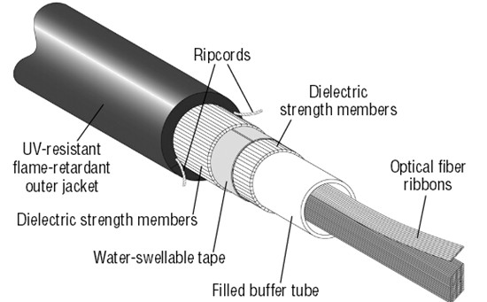
MTP cassettes and cable assemblies take their name from the MTP MPO connector, designed and introduced as a performance version of MPO connectors. MTP fiber systems are truly an innovative group of products. Each MTP connector contains 12 fibers or 6 duplex channels in a connector that is smaller than most duplex connections in use today. A 72 fiber trunk cable can be terminated with six MTP connectors and MTP connectors are manufactured specifically for multifiber loose tube or ribbon cable.

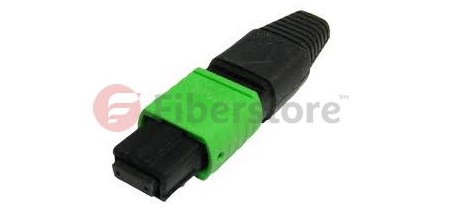
MTP connectors allow high-density connections between network equipment in telecommunication rooms. They use a simple push-pull latching mechanism for easy and intuitive insertion and removal. The ends of MTP brand connectors may be polished flat or at an 8° angle. An MTP brand connector is about the same size as a SC connector however it can accommodate 12 fibers, which provides up to 12 times the density, thereby requiring much less card and rack space.

MTP Cable

A standard MTP cassette has one port in the back with a MTP coupler awaiting connection of an MTP cable assembly that has 12 fibers in the connector. The MTP cable plugs into the back and through the adaptor. The cable connects to another MTP assembly inside the cassette that “fans out” to 12 SC or LC connections. One MTP cable can connect up 12 different ports. From there you simply plug in your patch cables.

APPLICATIONS

* Suitable for high-density switch to patching and distribution in Data Center Applications (based on 72 fiber MTP ferrule)
* Used in optical transmitters and receivers, MTP brand connectors offer up to 36 times the density of standard connectors, providing significant space and cost savings.
* Compact design addresses high fiber count applications, with small and lightweight cables ideal for use with installation space limitations.
* MTP brand cable trunks offer flexibility in changing the connector style in the patch panels. New cassettes can be installed with the new connector style on the cross-connect side of the patch panel without having to change the connector on the cable trunk.
* The MTP brand connector is the standard for delivery of 40G (in its 12 fiber version) and 100G (in either a duplexed 12 fiber cable or 24 fiber ferruled cable) using QSFP transceivers.

Multi-fiber technology will eventually replace the standards for fiber optics as we know it. Even now people are tearing out their existing infrastructure and placing MTP cassettes in their patch panels to route data for thousands of network electronics. MTP cassettes, cables, connectors and adapters are essential to backbone infrastructure. The high fiber count in one connector creates endless possibilities. Imagine a 1U rack mount patch panel that can supply data to run an entire 288-port switch. With today’s increasing demand for higher through-put, ST, SC, MTRJ, LC, FC, etc, will all be a thing of the past.

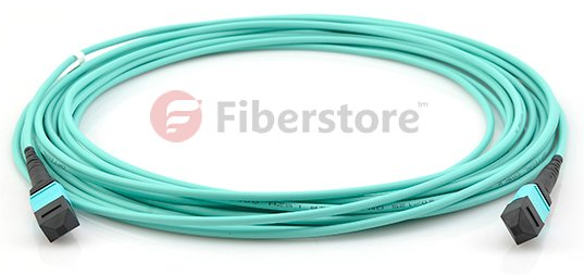
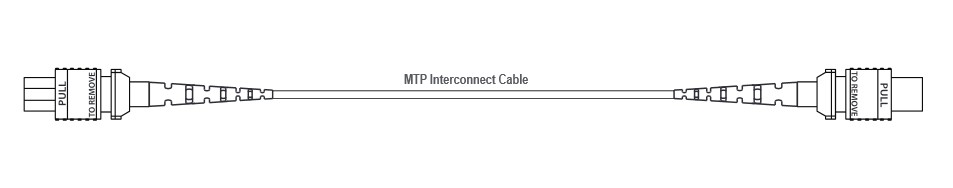
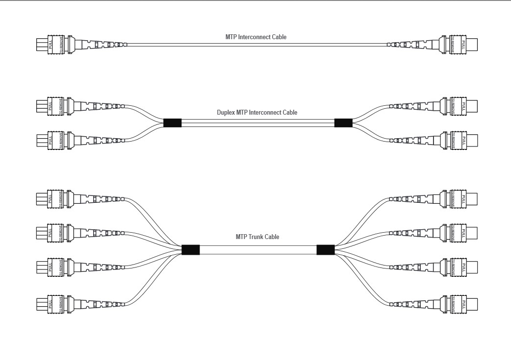
MTP Fiber Optic Cables are multi-fiber patch cords suitable for high-density back plane and PCB solutions. MTP patch cords offer up to 36 times the density (based on a 72 fiber ferrule) of traditional patch cords, providing significant space and cost savings. There are several configurations for MTP brand cable assemblies. The most popular is a MTP connector to MTP connector patch or trunk cable that connects an MTP brand cassette to another MTP brand cassette. If an MTP adapter panel is installed in a patch panel, then an MTP cable to MTP brand can be used as well.

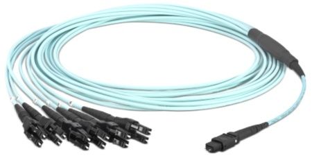
Another configuration is MTP connectors to LC or SC fiber connector. These can be used in different applications for both back end and front end adapter panels, for instance, plug one MTP connector into the back and plug an MTP cable to LC cable into the front and have the 12 LC connections go to other equipment. If there is an MTP cassette that needs to be lit up by using a 12-fiber LC adapter panel, plug each of the 12 LC connections in the LC adapter panel. The MTP side then plugs into the back of the cassette. Increase the transfer speed with 10 Gig 50 Micron multimode cable or increase the distance the signal can travel using singlemode. Cables may be constructed of ribbon fiber, small form factor loose tube assembly cable, or subgrouped trunking cable. The options are only limited by the application.

MTP/MPO Cassettes are specially designed to reduce installation time and cost for an optical network infrastructure in the premises environment. MTP/MPO Cassettes provide secure transition between MTP/MPO and SC, LC, ST, or FC connectors. They are used to interconnect MTP/MPO backbones with LC/SC/ST/FC patching. Fiberstore MTP cassettes come in a variety of connector styles and modes. From Multimode to Singlemode, from SC to LC, MTP brand solutions can be the solution to save space, time, and energy.

MTP Trunk Cable

By plugging an MTP brand cable into the back, 12 or 24 (with quad LC) connections are being lit up . For the 24-fiber application, either one 24-fiber MTP brand cable or two 12-fiber MTP brand cables can be used. The cassette can be snapped into any standard fiber optic patch panel including both rack mount and wall mount. A RAC-1X holds three of these cassettes which could potentially contain 72 active LC connections using only three (or six) MTP brand cables. Clean up the clutter and increase your possibilities using MTP brand cassettes.

We supply MPO/MTP fiber optic cables, such as MPO MTP trunk cable, MPO/MTP breakout cable. These are available in Female to female or a male to male and male to female configurations. The male version has MTP pins. These can be made with 12 fiber MTP connectors, 24 Fiber MTP connectors, 48 Fiber MTP connector variations. We use USConec MTP fiber optic connectors for all of our MTP and MPO terminations so that the highest performance is accomplished. Many additional options and combinations are available. All multi fiber optic cables are customizable.

24 Fiber Data Center Fiber Trunking and Interconnect Solution

Share

At the heart of every enterprise is a data center that manages information that drives the business. It’s a complex, everchanging infrastructure that must be able to adapt quickly. New technologies, platforms and media, as well as end user demands for exponentially growing bandwidth pose a relentless challenge to data center managers who must keep pace with this evolution. One key to successfully navigating these challenges is to implement a solid technology migration strategy.

How can you make the best use of technology to ensure your data center can support the next three generations of equipment and successfully take you to from 1 GbE to 10GbE. The following is the intrduction of 24 Fiber System Interconnect Solution.

The 10 Gigabit Interconnect Solution, like all of the planned migration designs, employs a 24-fiber cassette with a single MPO-type connector at each end. A trunk interfaces with the rear of a 24-fiber MPO cassette that breaks out the trunk fibers into twelve duplex LC connections at the front, supporting 24 fibers per cassette. This cassette resides in a time-proven chassis which provides cable management and protection for both the MPO at the rear and LC cords at the front. Fiber enclosures are stackable and available in 1, 2, and 4 RU versions and support up to 36 duplex LCs (72 fibers) per rack unit. They can be populated all at once, or added to or upgraded a cassette at a time in the future. The Fiber enclosure also supports high density 10 Gigabit cassettes, as well as 40 and 100 GbE versions, allowing an upgrade path by changing the cassette at the front and using existing and additional 24-fiber trunks at the rear. The following is we need in the 10 Gigabit Interconnect Solution.

24 fiber trunk cables are used to connect 24 fiber 10G, 40G and 100G MPO cassettes. MPO fiber trunk cable provide the possibility to make cross-connections or inter-connections to the equipment. In case the MPO cable is connected with MPO couplers, one of the MPO connectors must have pins.

The 24 fiber MPO trunk cables are constructed from 7.5mm loose tube gel filled indoor/outdoor rated cable. The transition at each end to 3.8mm round MPO tails is protected with a free floating fiber over-molded fan-out. On both sides of the MPO connector, the tails are protected with a clear plastic protection sleeve. The sleeve is closed with a re-usable tie-wrap which can be used to strain relieve the MPO trunk to the panel or cabinet at the over-molded fan-out. For placing/pulling the trunks over longer lengths, a re-usable IP67 protection/pulling kit can be ordered separately.

trunk cable

FEATURES

Pre-terminated low loss MPO trunk cable
OM3 or OM4 bend insensitive fiber glass in an LSZH loose tube cable
Mated MPO performance for OM3 and OM4:
Attenuation ≤ 0.25 dB(max.) RL ≥ 28 dB(min)
MPO tail length 80 cm

Each product is individually tested to ensure that its performance meets or exceeds the required standard. The test results are supplied with each product.
Protection / pulling kit can be ordered separately.

The 24-fiber data center fiber trunking and interconnect solution is ideal for medium- to large-size data center customers and markets, from healthcare and finance to broadcasting and government—essentially anyone that foresees the need to update from 10- to 40/100-GbE in the future. With guaranteed support for all three applications, the ability to use all the fiber deployed, reduced cable congestion and better airflow, higher port densities in fiber panels and an easy migration scheme, the data center fiber trunking and interconnect solution with 24-fiber trunk cables offers lower future capital and operating expense.