Author Archives: Alice.Gui

What’s the Difference: OM3 vs OM4

Share

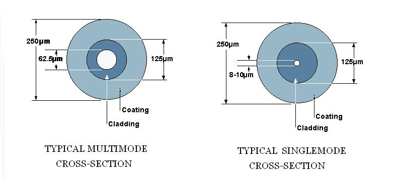
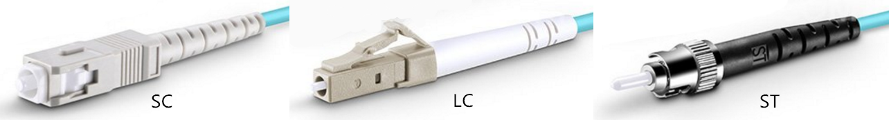
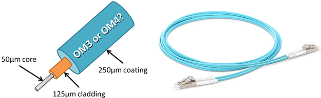
OM3 and OM4 are two common types multimode fiber used in local area networks, typically in backbone cabling between telecommunications rooms and in the data center between main networking and storage area network (SAN) switches. Both of these fiber types are considered laser-optimized 50/125 multimode fiber, meaning they both have a 50μm micron diameter core and a 125μm diameter cladding, which is a special coating that prevents light from escaping the core. Both fiber types use the same connectors, the same termination and the same transceivers—vertical-cavity surface emitting lasers (VCSELs) that emit infrared light a 850 nanometers(nm). OM3 is fully compatible with OM4. With so many similarities, and often manufactured with the same color aqua cable jacket and connectors, it can be difficult to tell these two fiber types apart. So, what’s the difference between OM3 vs OM4? Do these two types fiber refer to the same thing?

OM3 vs OM4

What’s the Difference: OM3 vs OM4

In fact, the difference between OM3 vs OM4 fiber is just in the construction of the fiber optic cable. The difference in the construction means that OM4 cable has better attenuation and can operate at higher bandwidth than OM3. What is the reason of this? For a fiber link to work, the light from the VCSEL transceiver much have enough power to reach the receiver at the other end. There are two performance values that can prevent this—optical attenuation and modal dispersion.

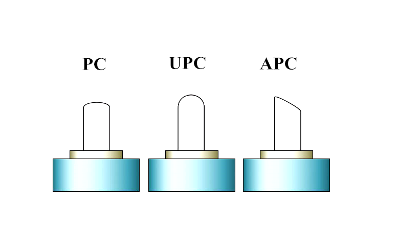
Attenuation is the reduction in power of the light signal as it is transmitted (dB). Attenuation is caused by losses in light through the passive components, such as cables, cable splices, and connectors. As mentioned above the connectors are the same so the performance difference in OM3 vs OM4  is in the loss (dB) in the cable. OM4 fiber causes lower losses due its construction. The maximum attenuation allowed by the standards is shown below. You can see that using OM4 will give you lower losses per meter of cable. The lower losses mean that you can have longer links or have more mated connectors in the link.

Maximum attenuation allowed at 850nm: OM3 <3.5 dB/Km; OM4 <3.0 dB/Km

Light is transmitted at different modes along the fiber. Due to the imperfections in the fiber, these modes arrive as slightly different times. As this difference increases you eventually get to a point where the information being transmitted cannot be decoded. This difference between the highest and lowest modes is known as the modal dispersion. The modal dispersion determines the modal bandwidth that the fiber can operate at and this is the difference between OM3 and OM4. The lower the modal dispersion, the higher the modal bandwidth and the greater the amount of information that can be transmitted. The modal bandwidth of OM3 and OM4 is shown below. The higher bandwidth available in OM4 means a smaller modal dispersion and thus allows the cable links to be longer or allows for higher losses through more mated connectors. This gives more options when looking at network design.

Minimum Fiber Cable Bandwidth at 850nm: OM3 2000 MHz·km; OM4 4700 MHz·km

Choose OM3 or OM4?

Since the attenuation of OM4 is lower than OM3 fiber and the modal bandwidth of OM4 is higher than OM3, the transmission distance of OM4 is longer than OM3. Details are shown in the table below. According to your network scale, to choose a more suitable cable type.

Fiber Type 100BASE-FX 1000BASE-SX 10GBASE-SR 40GBASE-SR4 100GBASE-SR4
OM3 2000 Meters 550 Meters 300 Meters 100 Meters 100 Meters
OM4 2000 Meters 550 Meters 400 Meters 150 Meters 150 Meters

Since OM4 performs better than OM3 cables, usually, OM4 cable is about twice as expensive as OM3 cable. This may be a big limited factor of OM4 cables’ application. However, if you choose to shop in Fiberstore, you may get much cheaper OM4 fiber nearly the same as the OM3 fiber. Price of different types OM3 and OM4 cables in Fiberstore is listed in the table below:

Fiber Type 3m Standard LC duplex 3m Armored LC duplex 3m HD LC duplex 3m Standard MTP
OM3 US$ 3.30 US$ 7.20 US$ 22.00 US$ 49.00
OM4 US$ 4.00 US$ 8.00 US$ 24.00 US$ 54.00

Either OM3 or OM4 cable can satisfy your unique cabling needs. Just choose the most suitable one for your network to cost less and achieve more.

Related Article: OM3 OR OM4 Cable Which One Do You Need?

Related Article: Multimode Fiber Types: OM1 vs OM2 vs OM3 vs OM4 vs OM5

Cat5e vs Cat6: Can Cat6 Use on Cat5e Patch Panel or Vice Versa?

Share

In the market, there exist both Cat5e patch panel and Cat6 patch panel. We know that Cat5e patch panels are meant to be used with Cat5e patch cable, and Cat6 patch panels are meant to be used with cable Cat6, but what’s the Cat5e vs Cat6 differences, and Cat5e patch panel vs Cat6 patch panel differences? Can I use Cat6 cable on Cat5e patch panels or can I use Cat5e cable on Cat6 patch panels? Answers will be provided in this blog.

Cat5e vs Cat6: Cat6 on Cat5e Patch Panel

Cat5e vs Cat6 Differences: Can I Use Cat6 on Cat5e Patch Panel?

There isn’t much practical difference in the patch panels themselves. There is a difference in the wire gauge specified between Cat5e/Cat5 vs Cat6 Ethernet cable. The Cat6 wire is thicker. Cat6 usually has 23AWG copper conductors compared to only 24 AWG in Cat5e cable. Another factor making Cat6 a larger wire than Cat5e is the fact that between each of the four pairs in a Cat6 cable there is a spline that will separate each pair from one another. Separating the pairs helps reduce cross-talk between the pairs and gives you a better signal. However, this spline also increases the diameter of the cable. Regardless of the size difference in Cat5e vs Cat6, the fact was that Cat6 cable is backward compatible with Cat5e. Yes, Cat6 is often times a larger cable, but this in no way affects its use with Cat5e patch panels. Feel free to use Cat5e patch panels if you already have them. You can always upgrade them later.

Cat5e vs Cat6: Can I Use Cat5e on Cat6 Patch Panel?

In addition to using Cat6 on Cat5e patch panel, we may also across some situations where we want to use Cat5e on a Cat6 patch panel. According to the passage above, we know that Cat6 cable is thicker than Cat5e, so if I use Cat5e on a Cat6 patch panel, will it be too loose? Although Cat6 individual twisted pairs insulation is usually thicker than Cat5e, this is usually never a problem with termination, only with how many cables you can stuff through a piece of conduit. So, will a Cat5e cable be “looser” terminated on a Cat6 jack, slightly yes, but electrically it will still make contact and work fine. But you should mind that your cabling channel will default to the lowest Catx component. Even though the patch panel says Cat6, with Cat5e cables you should only expect Cat5e performance on those jacks.

Conclusion

When punching down Cat5e wire on a Cat6, the Cat5e wire is enough smaller that it is possible to get what looks like a good punch, but the insulation on the wire is not actually penetrated or is only partially penetrated by the vampire jaw of the punch block. When punching down Cat6 wire on a Cat5e panel, the larger wire can end up bending or even breaking the vampire jaws on the punch down block. In both cases, using care and testing each connection, you can usually make it work. If you’re just doing one panel at home you are probably OK. Although it can both work well, we don’t recommend to do this. Use the Cat5e on Cat5e patch panel and Cat6 on Cat6 patch panel will get the best performance. FS.COM provide both high-density Cat5e patch panels for Fast Ethernet applications and Cat6 patch panels for 1-Gigabit Ethernet applications. Easy to management and conserves data centers rack space. For more information, please visit www.fs.com.

Related Articles:
How to Select the Suitable Copper Patch Panel?
Home Ethernet Wiring Guide: How to Get a Wired Home Network?
Quick View of Ethernet Cables Cat5, Cat5e And Cat6

GLC-T vs GLC-TE vs SFP-GE-T: Which One to Choose?

Share

GLC-T, GLC-TE and SFP-GE-T are three Cisco 1000BASE-T SFP types. All these three models SFPs can operate on standard Category 5 unshielded twisted-pair copper cabling of link lengths up to 100 m (328 ft) and support 10/100/1000 auto negotiation and Auto MDI/MDIX. So, what’s the difference between them? In this article, comparison between Cisco GLC-T vs GLC-TE vs SFP-GE-T will be provided.

GLC-T vs GLC-TE vs SFP-GE-T on Cisco switch

Specifications for GLC-T, GLC-TE and SFP-GE-T

By access to Cisco’s relative information, specifications for Cisco GLC-T, GLC-TE and SFP-GE-T are concluded in the table below:

SFP Models Description Operating Temperature Range
Cisco GLC-T 1000BASE-T SFP Copper RJ-45 100m Transceiver COM
Cisco GLC-TE 1000BASE-T SFP Copper RJ-45 100m Transceiver EXT
Cisco SFP-GE-T 1000BASE-T SFP Copper RJ-45 100m Transceiver NEBS 3 ESD EXT

From the table above, we can see that the difference between GLC-T and GLC-TE is the operating temperature range. Operating temperature range for GLC-T and GLC-TE is respectively commercial temperature range (COM) and Extended temperature range (EXT). The difference between SFP-GE-T and GLC-TE is that the SFP-GE-T has the function of NEBS 3 ESD. Then what does that mean? Let’s read the following passages.

Explanation for SFP Operating Temperature Range: COM, EXT and IND

Operating temperature range:

  • Commercial temperature range (COM): 0 to 70°C (32 to 158°F)
  • Extended temperature range (EXT): -5 to 85°C (23 to 185°F)
  • Industrial temperature range (IND): -40 to 85°C (-40 to 185°F)
  • Storage temperature range: -40 to 85°C (-40 to 185°F)
What Does NEBS 3 ESD Mean?  

NEBS is short for Network Equipment Building System and is a set of standards for building networking equipment which can withstand a variety of environmental stresses. NEBS has three levels: Level 1, Level 2, and Level 3. Level 1 refers to cases where minimum compatibility with the environment is needed. Level 2 applies for limited operability of the product. Finally, NEBS Level 3 (NEBS 3 ESD) certification guarantees the maximum operability of the equipment. It also certifies that the equipment will perform well in harsh environmental conditions and will not interfere with other electronic devices around. NEBS Level 3 certified networking equipment is vital in mission-critical applications. SFP-GE-T with 1000BASE-T NEBS 3 ESD, that is to say, compared to GLC-T or GLC-TE it can take greater stresses with less likelihood of failure, and are therefore a bit more trustworthy in truly mission-critical applications.

Which One Should I Use: GLC-T vs GLC-TE vs SFP-GE-T

In terms of Cisco original GLC-T vs GLC-TE vs SFP-GE-T transceivers, GLC-T and SFP-GE-T will be End-of-Sale June 1, 2017 and replaced by the GLC-TE. So then you can only buy GLC-TE transceivers from Cisco. If you’re dealing directly with a company like a telecom who specifically requires NEBS compliance, they’ll let you know and you should choose SFP-GE-T. But for most of the networks, GLC-T and GLC-TE transceivers are all you’d need for Gigabit Ethernet, and they cost less as well. Fiberstore (FS.COM) provides all these three SFP modules. We are manufactured to the exact same standards as Cisco’s own brand, and come with true lifetime warranties. Every SFP module in Fiberstore was tested to ensure 100% compatibility, but only cost a small fraction of name-brand alternatives.

Related Article: Compatible SFP for Cisco 2960 Series Switches

Related Article: A Quick Overview of Cisco 1000BASE-T GLC-T SFP Copper Module

Full CWDM Mux Demux and CWDM SFP Transceivers Solutions

Share

CWDM systems have channels at wavelengths spaced 20 nanometers (nm) apart, compared with 0.4 nm spacing for DWDM. This allows the use of low-cost, uncooled lasers for CWDM. In a typical CWDM system, laser emissions occur on full eighteen channels at eighteen defined wavelengths: 1610 nm, 1590 nm, 1570 nm, 1550 nm, 1530 nm, 1510 nm, 1490 nm, 1470 nm, 1450 nm, 1430 nm, 1410 nm, 1390 nm, 1370 nm, 1350 nm, 1330 nm, 1310 nm, 1290 nm, 1270 nm. Besides, for CWDM systems an industry standard color coding scheme is used. The latches of the CWDM SFP transceivers match the colored port indicators on the passive units therefore guaranteeing simple setup. Following color codes and wavelength are valid for CWDM.

cwdm-channels

Full CWDM Channels (18 Channels) Mux Demux Solution

The WDM system uses a multiplexer at the transmitter to combine several wavelengths together, each one carry different signal with bite-rate up to 10G and a demultiplexer at the receiver to split them apart. Both mux and demux are passive, requiring no power supply. The 18 Channels CWDM mux demux covers all channels of 1270nm to 1610nm in 20nm increments. Without replacing any infrastructure, it totally support data rates up to 180 Gbps by being completely protocol transparent. The main fields of applications are the use in SDH (STM-1, STM-4, STM-16, STM- 64), IP (Fast Ethernet, Gigabit Ethernet, 10 Gigabit) ATM and storage (1G, 2G, 4G, 8G, 10G Fibre Channel) networks. Connectors, located on the front of the CWDM mux demux modules, are labeled and use the same color-coding that is used to indicate the wavelength of the individual CWDM SFP transceivers (shown in the figure below).

cwdm-mux-demux

When fiber availability is limited, CWDM mux demux could increase the bandwidth on the existing fiber infrastructure. By using 18ch CWDM mux demux mentioned above and the CWDM SFP transceivers, up to 180 Gbps could be supported on a fiber pair.

18-channels-cwdm-mux-demux

Full CWDM SFP Transceivers Solution

CWDM SFP transceiver is based on the SFP form factor which is a MSA standard build. The max speed of this product is 1.25G and they are also available as 2.5G and of course the popular CWDM 10G SFP transceivers. The CWDM SFP transceiver has a specific laser which emits a “color” defined in the CWDM ITU grid. The CWDM ITU grid is defined from 1270 to 1610nm and has steps of 20nm. So the available wavelength is 1270nm, 1290nm, 1310nm, 1330nm, 1350nm, 1370nm, 1390nm, 1410nm, 1430nm, 1450nm, 1470nm, 1490nm, 1510nm, 1530nm, 1550nm, 1570nm, 1590nm and C. Besides, our CWDM SFP transceivers are similarly color-coded as the CWDM mux demux to help you match the right link connection (shown in the figure below).

CWDM SFP

We can make the CWDM SFP transceivers compatible with every brand (Cisco, HP, H3C, Juniper, Huawei, Brocade, Arista). A lot of brands have vendor locking and only with the proper coding. Fiberstore is specialized in this rebranding or recoding. We have many different switches and routers in our test lab to test the coding. We also use different Optical Spectrum Analyzers to ensure the CWDM SFP transceiver is emitting the right color and has the correct power budget. The CWDM SFP transceiver is used in combination with passive CWDM mux demux, and we can provide you a complete solution and advice on which equipment fits best in your project. Please give us your project details and we will provide the most efficient and economical solution.

1270nm SFP 1290nm SFP 1310nm SFP 1330nm SFP 1350nm SFP 1370nm SFP
1390nm SFP 1410nm SFP 1430nm SFP 1450nm SFP 1470nm SFP 1490nm SFP
1510nm SFP 1530nm SFP 1550nm SFP 1570nm SFP 1590nm SFP 1610nm SFP

How to Choose Right Category 5e Cable for Your Network?

Share

Category 5e Cable (Cat 5 enhanced), also know as Cat5e, is currently the most commonly used Ethernet cable in new installations. It’s designed to greatly reduce crosstalk, which means the Cat5e is better at keeping signals on different circuits or channels from interfering with each other. A step above Cat 5, it can handle 1000 Mbps speeds (gigabit Ethernet) at 100 MHz wit a maximum cable length of 328 feet (100 meters). How to choose right Category 5e Cable for your network? This article may give you the answer.

Category 5e Cable

Straight-Through or Crossover Category 5e Cable?

RJ-45 conductor Cat 5e cable contains 4 pairs of wires each consists of a solid colored wire and a strip of the same color. There are two wiring standards for RJ-45 wiring: T-568A and T-568B. The two wiring standards are used to create a cross-over cable (T-568A on one end, and T-568B on the other end), or a straight-through cable (T-568B or T-568A on both ends). To create a straight-through Cat 5e, you’ll have to use either T- 568A or T-568B on both ends of the cable. To create a cross-over Cat 5e cable, you’ll wire T-568A on one end and T- 568B on the other end of the cable.

straight-through-or-crossover-cat5e-cable

The straight-through Cat 5e cables are used when connecting Data Terminating Equipment (DTE) to Data Communications Equipment (DCE), such as computers and routers to modems (gateways) or hubs (Ethernet Switches). The crossover Cat 5e cables are used when connecting DTE to DTE, or DCE to DCE equipment, such as computer to computer, computer to router or gateway to hub connections. The DTE equipment terminates the signal, while DCE equipment do not.

Unshielded(UTP) or Shielded(STP) Category 5e Cable?

Shielded twisted cables (STP) reduce electrical noise and electromagnetic radiation. In other words, they help to keep the signal steady, and reduce interference with other devices. This is done with a shield that may be composed of copper tape, a layer of conducting polymer or a braid, and is covered with a jacket. Unshielded twisted cables (UTP) by definition do not have shielding serving them to reduce interference. They are designed to cancel electromagnetic interference with the way the pairs are twisted inside the cable.

unshieldedutp-or-shieldedstp-cat5e-cable

If you’re in any situation where you want to make sure that you get the most speed and efficiency out of your network, you’ll probably want to use shielded Cat5e cable. It’s hard to know when and where you’ll run into enough EMI to cause a problem, but if you use shielded Cat 5e in the first place you won’t have to worry about tearing the cable from the wall to replace it if you do run into that problem. Due to the design and nature of unshielded Cat 5e, it is most suitable for office LANS and similar network cabling systems. Unshielded Cat 5e are lightweight, thin and flexible. They are also versatile and inexpensive. When properly installed, a well-designed unshielded Cat 5e cable will be easier to both install and maintain than a shielded one.

Length and Color Options of Category 5e Cable

When choosing Cat 5e cable for your network, you also need to consider length and color. Cat 5e Ethernet cables come in standard lengths such as 1, 3, 5, 7, and 10 meter. Longer lengths are available, and you can also have custom cable lengths made. The distance between your various network devices and your network switch or router will determine the length you need. Cat5e cables come in all sorts of colors. This decision can be based purely on your individual tastes and preference. Blue is perhaps the most common, but you might also consider white, gray, or some other color that doesn’t clash with your walls and carpet. Pictures below shows ten colors of Cat 5e cable provided in Fiberstore.

cat-5e-color

Conclusion

Cat 5e cable supports up to 100 MHz and speeds up to 1 Gbps over 100 meters of cable. Cat 5e crossover patch cable is usually used to connect two same of type of devices. Besides, snagless boot prevents unwanted cable snags during installation and provides extra strain relief.

snagless-booted-cat5e-cable

The table below listed several most popular Cat 5e cables sold in Fiberstore for your choice.

FS P.N. Description
22831 3m Cat 5e Purple Snagless Booted Unshielded(UTP) PVC Ethernet Network Patch Cable
22842 20m Cat 5e Blue Snagless Booted Unshielded(UTP) LSZH Ethernet Network Patch Cable
13826 3m Cat 5e Green Non-booted Unshielded(UTP) PVC Ethernet Network Patch Cable
22775 1m Cat 5e Purple Snagless Booted Unshielded(UTP) PVC Ethernet Network Patch Cable
22835 2m Cat 5e Blue Snagless Booted Unshielded(UTP) LSZH Ethernet Network Patch Cable

Related Articles:

Ethernet Cable Types – Cat5e, Cat6, Cat6a, and Cat7

Quick View of Ethernet Cables Cat5, Cat5e And Cat6

Patch Cable vs. Crossover Cable: What Is the Difference?

Common Mistakes in Fiber Optic Network Installation

Share

When install a fiber optic network, people may make some common mistakes, which were usually overlooked. In this article, I will list the most common ones. Hope to give you some guidance for your optical network installation.

1. Single Strand Fiber Device Must Be Used in Pairs

You will never buy two left shoes, but people often make a similar mistake when they’re working with Single Strand Fiber (SSF). Single strand fiber technology allows for the use of two independent wavelengths, such as 1310 and 1550 nm, on the same piece of cable. The most common single strand fiber device is Bi-Directional (BiDi) transceiver. Two BiDi transceiver must be matched correctly. One unit must be a 1310nm-TX/1550nm-RX transceiver (transmitting at 1310 nm, receiving at 1550 nm) and the other must be a 1550nm-TX/1310nm-RX transceiver (transmitting at 1550 nm, receiving at 1310 nm). The 1550nm-TX/1310nm-RX transceiver is more expensive than the 1310nm-TX/1550nm-RX transceiver, due to the cost of their more powerful lasers. So network engineers may hope to save money by installing a pair of 1310nm-TX/1550nm-RX transceivers. But, like mismatched shoes, it doesn’t work.

single-strand-fiber

2. Don’t Use Single-Mode Fiber over Multimode Fiber

Some people may want to make use of legacy cabling or equipment from an older fiber installation to save cost. But keep in mind that single-mode and multimode fiber are usually incompatible. Multimode fiber uses cable with a relatively large core size, typically 62.5 microns (om2, om3 and om4), and 50 microns (om1) still used in some installations. The larger core size simplifies connections and allows for the use of less powerful, less expensive light sources.  But the light therefore tends to bounce around inside the core, which increases the modal dispersion. That limits multimode’s useful range to about 2 km. Single-mode fiber combines powerful lasers and cabling with a narrow core size of 9/125 microns to keep the light focused.  It has a range of up to 120 km, but it is also more expensive. If you tried to use single-mode fiber over a multimode fiber run.  The core size of the fiber cable would be far too large.  You’d get dropped packets and CRC errors.

single-mode-multimode-fiber

3. Understand All kinds of Fiber connectors First

Fiber optic transceivers use a variety of connectors, so make clear their differences before you begin ordering products for a fiber installation is necessary. SC (stick and click) is a square connector. ST (stick and twist) is a round, bayonet-type. LC, or the “Lucent Connector”, was developed by Lucent Technologies to address complaints that ST and SC were too bulky and too easy to dislodge. LC connectors look like a compact version of the SC connector. SFP (small form‐factor pluggable) transceivers usually use LC connector.  Less common connectors include MT-RJ and E2000.

st-lc-sc

4.Connector Links and Splice Times Also Affect 

Although single-mode fiber suffers from less signal loss per km than multimode, all fiber performance is affected by connectors and splices. The signal loss at a single connector or splice may seem insignificant. But as connectors and splices become more numerous signal loss will steadily increase. Typical loss factors would include 0.75 dB per connector, 1 dB per splice, 0.4 dB attenuation per km for single-mode fiber and 3.5 dB attenuation per km for multimode fiber.  Add a 3 dB margin for safety. The more splices and connectors you have in a segment, the greater the loss on the line.

5. Don’t Use APC connector with UPC Connector

Fiber connections may use Angle Polished Connectors (APC) or Ultra Polished Connectors (UPC), and they are not interchangeable. There are physical differences in the ferules at the end of the terminated fiber within the cable (shown in the figure below).  An APC ferrule end-face is polished at an 8° angle, while the UPC is polished at a 0° angle. If the angles are different, some of the light will fail to propagate, becoming connector or splice loss. UPC connectors are common in Ethernet network equipment like media converters, serial devices and fiber‐based switches. APC connectors are typical for FTTX and PON connections.  ISPs are increasingly using APC.

apc-upc-connector

6. Don’t Connect SFP to SFP+ Transceivers

Small Form Pluggable (SFP) transceivers are more expensive than fixed transceivers.  But they are hot swappable and their small form factor gives them additional flexibility. They’ll work with cages designed for any fiber type and their prices are steadily dropping.  So they have become very popular. Standard SFPs typically support speeds of 100 Mbps or 1 Gbps. XFP and SFP+ support 10 Gbps connections. SFP+ is smaller than XFP and allows for greater port density.  Though the size of SFP and SFP+ is the same, you can’t connect SFP+ to a device (SFP) that only supports 1 Gbps.

Related Article: Optical Module Maintenance Methods and Installation Tips

High Density Rack Mount Fiber Patch Panel for Fiber Adapter Panels & MTP Cassettes

Share

When you’re dealing with fiber optic patch cables in your network, whether your installation is small or large, simple or complex, your fiber patch cables have to terminate somewhere, so make sure you’ve got the right fiber patch panel solution designed specially to protect them. As we know, fiber patch panels are either for patching or splicing applications. For patching fiber patch panel, which can hold either fiber adapter panels (FAPs) or MTP cassettes. Usually, a standard 1RU rack mount enclosure can hold 3 LGX FAPs or cassettes, however, a high density 1RU rack mount fiber patch panel can hold 4 HD FAPs or cassettes, which efficiently optimize space utilization and save more cost in rack cable management.

fiber-enclosures

Fiberstore’s FHD series high density rack mount fiber patch panel, including 1RU (FHD-1UFCE), 2RU (FHD-2UFCE) and 4RU (FHD-4UFCE) types, are designed to hold both FAPs and cassettes and can easily mount in EIA 19-inch racks or cabinets, which provide a comprehensive line of fiber distribution enclosures that provide a high density flexible and modular system for managing fiber terminations, connections, and patching in data center application to maximizing rack space utilization and minimizing floor space.

FHD-1UFCE—High Density 1RU Rack Mount Fiber Patch Panel

HD FAPs is an unloaded 1RU rack mount fiber patch panel that can support either 4 FHD fiber adapter panels or 4 FHD MTP modular cassettes, up to 96 fibers. Inside the fiber patch panel, you can install either slack spools or splice trays for patching applications or splicing applications, which provides a complete system solution for connectivity. As shown in the figure below, its size is 44.4mm(H)x483mm(W)x457.8mm(D). Besides the FHD-1UFCE, we also provide pre-loaded 4 FHD fiber adapter panels fiber patch panel.

High Density 1RU Rack Mount Fiber Enclosures

  • Related FHD Adapter Panel & FHD MTP Modular Cassette Size

Fiber Adapter Panels and MTP Cassettes

FHD-2UFCE—High Density 2RU Rack Mount Fiber Patch Panel 

FHD-2UFCE is an unloaded 2RU rack mount fiber patch panel that can support either 8 FHD fiber adapter panels or 8 FHD MTP modular cassettes, up to 192 fibers. Inside the fiber patch panel, you can also install either slack spools or splice trays for patching applications or splicing applications, which provides higher patch field density in fewer rack units saving valuable space. As shown in the figure below, its size is 88.4mm(H)x447mm(W)x414mm(D).

High Density 2RU Rack Mount Fiber Enclosures

FHD-4UFCE—High Density 4RU Rack Mount Fiber Patch Panel

FHD-4UFCE is an unloaded 4RU rack mount fiber patch panel that can support either 12 FHD fiber adapter panels or 12 FHD MTP modular cassettes, up to 228 fibers. Splice tray, cable management loops and slack spools accessories of FHD-4UFCE are simple, which assures flexibility and ease of network deployment and moves, adds, and changes. As shown in the figure below, its size is 177mm(H)x447mm(W)x414mm(D).

High Density 4RU Rack Mount Fiber Enclosures

No matter where your cabling is, or what function you need your fiber patch panel to deliver, FS.COM has the ideal fiber patch panel solution. Our fiber patch panels are available in any configuration and feature industry-leading port density. Both rack mount and wall mount fiber patch panel for single-mode and multimode applications are available. All fiber patch panels are highly adaptable and easy-to-configure design, holding FAP Adapter Panels or MTP Cassette with superior cable management, port identification, fiber accessibility and security.

Can I Use SFP Transceiver in SFP+ Slot?

Share

A common confusion about SFP and SFP+ compatibility is that if I can use the SFP module in SFP+ slot. When I connect the SFP transceiver to SFP+ transceiver, can SFP+ negotiate down to 1G? Or is it possible to use SFP+ module in the SFP port on my switch? Can SFP+ copper twinax cable can negotiate down to 1G to support SFP? Can 1G and 10G can exist in the same link? All these questions usually create a giant headache for many engineers. After looking up many relevant documentation, now I will conclusion the answers in this article.

SFP Can be Plugged into SFP+ Ports in Most Situations
I’m not sure about the specific switch model, but as a general rule of thumb, SFPs will work in SFP+ slot, but SFP+ optics do not work in SFP slots. It’s just a power availability thing. When you plug the SFP module in SFP+ port, the speed of this port is 1G not the 10G. And sometimes this port will lock the speed at 1G until you reload the switch or do some fancy set of commands. Besides, the SFP+ port usually can never support speed under 1G. That is to say, we can’t plug the 100BASE SFP in the SFP+ port. In fact, for this question, it may depend greatly on the switch models – sometimes SFPs are supported in SFP+ ports, and sometimes not. For example, almost all SFP+ ports of Cisco switch can support SFPs and many SFP+ ports of Brocade switch only support SFP+. Though it’s feasible often, it’s safer to ask your switch vendor for some information.

SFP module in SFP+ port

SFP+ Can’t Auto-negotiate Down to 1G to Support with SFP Module
To my knowledge, unlike copper SFPs which are available in 10/100/1000 auto-negotiation, optics such as SFP and SFP+ do not support auto negotiation at all. In fact, Most (95+%) SFPs and SFP+s will only run at the rated speed, no more, no less. Besides, there is no such thing as a SFP+ that does 1G on one side (towards the fiber) and then does 10G on another side (towards the unit). Though we can use SFP in SFP+ ports in many cases, that doesn’t mean a SFP+ plugged into the SFP+ slot can support 1G. In a fiber link, if we plug a SFP in the SFP+ port on one side (1G), and then plug a SFP+ in the SFP+ port on the another side (10G), this may not work! You just can’t have 10 GbE at one end and 1 GbE at the other. For this question, if you use SFP+ copper, it also can’t negotiate down to 1G.

When use SFP and SFP+ modules in your network, make sure the speed of both ends of the fiber link is the same. SFP modules may can be used in SFP+ slot, but a SFP can never be connected to a SFP+ module. For their different speeds, transmission distance and wavelength. 10 SFP+ only can use for 10G SFP+ port, and can never auto-negotiate to 1G.

Related Article: Can I Use the QSFP+ Optics on QSFP28 Port?

Related Article: SFP Module: What’s It and How to Choose It?

Related Article: Understanding Video SFP Transceivers

Compatible SFPs for Ubiquiti EdgeSwitch and UniFi switch

Share

The Ubiquiti EdgeSwitch targets the Broadband / ISP / Carrier market, which offers an extensive suite of advanced layer-2 switching features and protocols, and also provides layer-3 routing capability. The UniFi switch targets the Enterprise / SMB market, which is designed for a wider IT audience, and therefore, tend to be simpler, and easier to use. Both these two types Ubiquiti switchs are supported for SFP fiber connectivity and widely used among people. However, which SFPs can I use with my EdgeSwitch or UniFi switch? This article may give the answer on ubiquiti SFP compatibility.

Which Ubiquiti EdgeSwitch Should I Use?

The EdgeSwitch offers the forwarding capacity to simultaneously process traffic on all ports at line rate without any packet loss. The EdgeSwitch provides total, non-blocking throughput. Among 8-Port model up to 10 Gbps, 16-Port model up to 18 Gbps, 24-Port model up to 26 Gbps and 48-Port model up to 70 Gbps. The following table lists the comparison between EdgeSwitch modules, according to your specific need to choose the right one.

Model Total Non-Blocking Throughput Gigabit RJ45 Ports SFP+ Ports SFP Ports Max. Power Consumption
ES- 8- 150W 10 Gbps 8 N/A 2 150W
ES- 16- 150W 18 Gbps 16 N/A 2 150W
ES- 24- 250W 26 Gbps 24 N/A 2 250W
ES- 24- 500W 26 Gbps 24 N/A 2 500W
ES- 48- 500W 70 Gbps 48 2 2 500W
ES- 48- 750W 70 Gbps 48 2 2 750W
ES- 24- LITE 26 Gbps 24 N/A 2 25W
ES- 48- LITE 70 Gbps 48 2 2 56W
ES- 12F 16 Gbps 4 N/A 12 56W
ES- 16- XG 124 Gbps 4 12 N/A 56W
EdgeMAX – Which SFPs are compatible with EdgeSwitch?

The ubnt edgeswitch provides fiber connectivity options for your growing networks. The 8, 16, and 24-port models include two SFP ports, providing up to 1 Gbps uplinks. For high-capacity uplinks, the 48-port models include two SFP and two SFP+ ports, providing uplinks of up to 10 Gbps. Take the ES‑8‑150W for example, it has 8 Gigabit RJ45 ports and 2 Gigabit SFP ports for 10G applications (shown in the figure below). For SFP ports, we should use SFP modules and fiber patch cable.

edgeswitch
According to an article titled “Which SFPs are compatible with the EdgeSwitch?”published in Ubiquiti Help Center, the following SFP transceivers are compatible with EdgeSwitch (only listed can be found in Fiberstore here).

SFP Model Description
Cisco GLC-SX-MM 1000BASE-SX SFP 850nm 550m Transceiver
Cisco GLC-SX-MMD 1000BASE-SX SFP 850nm 550m DOM Transceiver
HP J4858C 1000BASE-SX SFP 850nm 550m DOM Transceiver
HP J4858A 1000BASE-SX SFP 850nm 550m DOM Transceiver
Cisco GLC-LH-SM 1000BASE-LX/LH SFP 1310nm 10km Transceiver
HP J4859B 1000BASE-LX SFP 1310nm 10km DOM Transceiver
HP J4859C 1000BASE-LX SFP 1310nm 10km DOM Transceiver
Cisco GLC-T 1000BASE-T SFP Copper RJ-45 100m Transceive
Cisco SFP-H10GB-CU1M 1m 10G SFP+ Passive Direct Attach Copper Twinax Cable
Brocade 10G-SFPP-TWX-0101 1m 10G SFP+ Passive Direct Attach Copper Twinax Cable
Which Ubiquiti UniFi Switch Should I Use?

The UniFi POE switch offers the forwarding capacity to simultaneously process traffic on all ports at line rate without any packet loss. For its total, non-blocking throughput, the 24port model supports up to 26 Gbps, while the 48-port model supports up to 70 Gbps. The following table lists the comparison between UniFi switch modules, according to your specific need to choose the right one.

Model Total Non-Blocking Throughput Gigabit RJ45 Ports SFP+ Ports SFP Ports Max. Power Consumption
US- 8- 150W 10 Gbps 8 N/A 2 150W
US- 16- 150W 18 Gbps 16 N/A 2 150W
US- 24- 250W 26 Gbps 24 N/A 2 250W
US- 24- 500W 26 Gbps 24 N/A 2 500W
US- 48- 500W 70 Gbps 48 2 2 500W
US- 48- 750W 70 Gbps 48 2 2 750W
UniFi – Which SFPs are compatible with UniFi Switch?

Each model includes two SFP ports for uplinks of up to 1 Gbps. The 48port model adds two SFP+ ports for high-capacity uplinks of up to 10 Gbps, so you can directly connect to a highperformance storage server or deploy a longdistance uplink to another switch. Take the US- 8- 150W for example, it has 8 Gigabit RJ45 ports and 2 Gigabit SFP ports for 10G applications (shown in the figure below). For SFP ports, we should use SFP modules and fiber patch cable.

us-8-150w
According to an article titled “Which SFPs can I use with UniFi switch?”published in Ubiquiti Help Center, the following SFP transceivers are compatible with EdgeSwitch. Since among some SFP module types are the same as the EdgeSwitch, I only list the different SFPs here.

SFP Model Description
Fiberstore SFP-1G85-5M

Now: SFP1G-SX-85

1000BASE-SX SFP 850nm 550m DOM Transceiver
Cisco SFP-10G-SR 10GBASE-SR SFP+ 850nm 300m DOM Transceiver
Fiberstore SFP-10G85-3M

Now:
SFP-10GSR-85

10GBASE-SR SFP+ 850nm 300m DOM IND Transceive
Ubiquiti SFP Compatibility: Ubiquiti Compatible SFPs in Fiberstore

Fiberstore (FS.COM) provides a series of Ubiquiti compatible SFP transceivers that can be used with EdgeSwitch and UniFi switch. In Ubiquiti Networks Community SFP modules compatibility section, some people tested Fiberstore SFP modules in their EdgeSwitch. As shown in the figure below, SFP1G-SX-85, SFP1G-SX-31 and SFP-10GSR-85 SFPs are working.

sfp-modules-compatibility

Related Article: 3rd Party Optical Transceivers vs OEM Switch Warranty

What Is The Difference: SFP vs SFP+

Share

As we know, a SFP module just looks the same as the SFP+ module. And most switches can both support SFP module and SFP+ module. So, do these two modules really refer to the same one? What’s the difference between SFP vs SFP+?

SFP vs SFP+

SFP vs SFP+: SFP Definition
SFP stands for Small Form-factor Pluggable. It is a hot-pluggable transceiver that plugs into the SFP port of a network switch and supports SONET, Gigabit Ethernet, Fibre Channel, and other communications standards. SFP specifications are based on IEEE802.3 and SFF-8472. They are capable of supporting speeds up to 4.25 Gbps. Due to its smaller size, SFP replaces the formerly common gigabit interface converter (GBIC). Therefore SFP is also called Mini-GBIC. By choosing different SFP module, the same electrical port on the switch can connect to different fiber types (multimode or single-mode) and different wavelengths.

SFP module Cisco

SFP vs SFP+: SFP+ Definition
Since SFP supports only up to 4.25 Gbps, SFP+ that supports data rates up to 16 Gbps was later introduced. In fact, SFP+ is an enhanced version of the SFP. The SFP+ specifications are based on SFF-8431. In today’s most applications, SFP+ module usually supports 8 Gbit/s Fibre Channel, 10 Gigabit Ethernet and Optical Transport Network standard OTU2. In comparison to earlier 10 Gigabit Ethernet XENPAK or XFP modules, SFP+ module is smaller and becomes the most popular 10 Gigabit Ethernet module in the market.

SFP+ module Cisco

SFP vs SFP+
Review the SFP and SFP+ definition mentioned above, we can know that the main difference between SFP and SFP+ is the data rate. And due to different data rate, the applications and transmission distance is also different.

Ethernet Application

SFP (1Gbps) SFP+ (10Gbps)
1000BASE-SX SFP 850nm 550m

1000BASE-LX/LH SFP 1310nm 20km

1000BASE-EX SFP 1310nm 40km

1000BASE-ZX SFP 1550nm 80km

10GBASE-SR SFP+ 850nm 300m

10GBASE-LRM SFP+ 1310nm 220m

10GBASE-LR SFP+ 1310nm 10km

10GBASE-ER SFP+ 1550nm 40km

10GBASE-ZR SFP+ 1550nm 100km

Fiber Channel Application

SFP (2G, 4G) SFP+ (8G)
2.125Gbps:

2G Fibre Channel SFP 1310nm 2km/15km/20km/40km

2G Fibre Channel SFP 1510nm 80km

4.25Gbps:

4G Fibre Channel SFP 850nm 150m

4G Fibre Channel SFP 1310nm 5km/10km/15km/20km

8.5Gbps:

8G Fibre Channel SFP+ 850nm 150m

8G Fibre Channel SFP+ 1310mn 10km/20km/40km

8G Fibre Channel SFP+ 1510nm 80km

SONET/SDH Application

SFP (155Mbps, 622Mbps, 2.5Gbps) SFP+ (10G)
155Mbps:

OC-3/STM-1 1310nm 2km/15km/40km

OC-3/STM-1 1510nm 80km

622Mbps:

OC-12/STM-4 1310nm 500m/2km/15km/40km

OC-12/STM-4 1510nm 80km

2.5Gbps:

OC-48/STM-16 1310nm 2km/15km/40km

OC-48/STM-16 1510nm 80km

OC-192/STM-64 850nm 300m

OC-192/STM-64 1310nm 2km/10km/20km/40km

OC-192/STM-64 1510nm 80km

As we’ve explained the difference of SFP vs SFP+. Usually, SFP module plugs into SFP port of the switch and SFP+ module plugs into SFP+ port of the switch. But, sometimes SFP module can also be plugged into SFP+ port. Which SFP or SFP+ module should you choose all depends on your switch types. Fiberstore is a reliable SFP transceiver module manufactures, all SFP module and SFP+ module types are available in FS.COM. Besides, SFP+ cable is also provided. What’s more, the price of SFP module and SFP+ module is lower than many other manufactures. SFP test is strict in FS.COM. Matching fiber patch cable is also available.

Related Article: Compatible SFPs for Ubiquiti EdgeSwitch and UniFi switch

Related Article: SFP Module: What’s It and How to Choose It?

Related Article: Understanding Video SFP Transceivers