Category Archives: Cat5/Cat6/Cat7 Network Cable

Everything You Should Know About Cat7 Patch Cable

Share

Network Cable increasingly welcomed by the people. However, the rapid development of network applications increasing demand for bandwidth. As technology continues to progress, here comes a higher level of Cat7 patch cable to meet most commercial applications.

Cat7 Patch Cable Definition

Cat7 patch cable is referred to as Category 7 patch cable, Cat7 network cabling is used as a cabling infrastructure for 1000BASE-T (Gigabit Ethernet, or GbE) and 10GBASE-T (10-Gigabit Ethernet, or 10 GbE) networks.  The Cat7 standard provides performance of up to 600 MHz and can be used up to a maximum length of 100 meters.

Cat7 patch cable

Category 7 cable is able to achieve higher performance than preceding Ethernet standards such as Cat5, Cat5e and Cat6 by requiring each of its twisted wire pairs to be fully shielded.  This is known as Screen Shielded Twisted Pair (SSTP) or Screened Foiled Twisted Pair (SFTP) wiring, and it almost completely eliminates alien crosstalk while significantly improving noise resistance.

The Cat7 standard was published in 2002 by the International Organization for Standardization (ISO) and is also known as Class F cabling.  While more expensive than Cat 5e and Cat 6 cabling, Cat 7 cabling does have a 15-year lifecycle (compared to estimated 10-year lifecycles for Cat5e and Cat6), which helps improve its overall return on investment (ROI).

Cat 7 cable was developed with strict specifications on crosstalk and EMI protection. Cat 7 cable features four individually shielded pairs as well as an overall cable shield to protect the signals from crosstalk and EMI. Cat7 cable provides a copper solution for 10-Gigabit Ethernet at 100 meters.

Category 7 and fiber connectorCat7 cable is commonly terminated using a GG45 connector, which is a connector that it backwards compatible with the 8p8c RJ45 connectors used on Cat6 or Cat5e cable. The GG45 connector has four additional conductors that provide support for frequencies of up to 600MHz. The higher frequencies allow Cat7 patch cable to support 10-Gigabit Ethernet. Cat7 cable may also be terminated using TERA connectors, which were developed by Siemon™. The TERA connector has a unique footprint and is not compatible with a standard 8p8c (RJ45) connector. The TERA connector is also capable of supporting frequencies of up to 600MHz. The ability to support the higher frequencies allows Cat7 patch cable to carry more data. This allows Cat 7 patch cable to support Ethernet applications up to 10-Gigabit Ethernet.

What is the application for a data center?

Cat7 cabling will be used for backbone connections between servers within a data center. This provides a high-speed  interconnect used for data transfer within the network.

Does this replace fiber?
This provides an alternative to using fiber optic cabling within the data center. Cat7 cabling will provide similar performance to some fiber solutions. The cost of equipment that supports copper cabling is typically less than equipment that supports fiber cabling. Another advantage is that the copper cabling is not as fragile as fiber cabling.

What’s the practical performance difference with Cat5e/6?
Cat7 patch cable is designed to support much higher frequency signals than Cat5e and Cat6.This allows Cat7 cabling to carry a larger amount of information. Cat7 cable is also able to better protect the signals traveling over the cable. The shielding as well as the tighter twists of the pairs in Cat7 cable lessens the effects of crosstalk and EMI.

Is Cat 7 widely used?
Currently, Cat7 Patch Cable is not widely adopted. Cat5e and Cat6 solutions sufficiently support the bandwidth requirements of today’s data centers, networks, and end users. Using Cat7 for a connection to a desktop would be unnecessary because the bandwidth would not be utilized. It may also be an unnecessary expense for many data center applications for the same reason. However, as technology advances and requirements increase, Cat7 cable will become more relevant in the data center and desktop connections.

FS.COM provides cheap fiber optic cable as well, which has high quality and low price! Come and buy your need fiber optic cable.

Related Articles:
Ethernet Cable Types – Cat5e, Cat6, Cat6a, and Cat7
Difference of Straight Through and Crossover Cable
Patch Cable vs. Crossover Cable: What Is the Difference?
Quick View of Ethernet Cables Cat5, Cat5e And Cat6

Why Choose Shielded Cable for Cabling System?

Share

Shielded VS. Unshielded Cabling

In copper structured cabling system at all levels, there are two main network cable technical types: Shielded and Unshielded cabling systems. Both types have been in existence since the earliest cabling standards were defined. Shielded cabling using shielded cable became popular from the outset in countries like Germany, Austria, Switzerland and France, while U/UTP was quickly adopted in the rest of the world. Although both systems work fine at 1 Gigabit Ethernet data rates, shielded systems can demonstrate superior performance at higher data rates such as 10G due to their ability to reliably support higher frequency transmission.

Cable structure shielded cable vs unshielded cable

What Is the Function of a Shielded Cable?

F/UTP Shielded Cable

F/UTP cable shielding structure: Four pairs of wires in the data cable have a layer of aluminum foil shielded, this layer of shielding (also called screening) protects against EMI/FRI and crosstalk.

S/FTP Shielded Cable

In S/FTP structure, in addition to the braided foil shield, the four twisted pairs have a layer of aluminum foil shield respectively to protect the transmission signal and make sure they do not interfere with each other, making near-end crosstalk attenuation (NEXT) performance dramatically good. Better NEXT performance means higher SNR and better transmission quality and faster system output. S/FTP shielded cables’ excellent NEXT structural performance can not be compared by other cables (such as non-shielded U/UTP). Therefore, ISO11801 on the Cat7 cable (600MHz) and Cat7a  (1000MHz) only provides the S/FTP cable structure, U/UTP cannot meet.

10GBase-T Makes Data Cable Face New Problem: Alien Crosstalk

2006 Copper Gigabit Ethernet applications published the proposed new standard transport protocols 10GBASE-T. Compared to 1000Base-T, its transmission rate increased 10 times. 1000BASE-T copper cabling has requirements for parameters (Attenuation, NEXT, Return Loss, etc.). The bandwidth required to reach 1-100MHz with UTP Cat5e (Class D) cabling system. 10GBASE-T cabling channel requirements of all component parameters have to be up to 500MHz bandwidth, which requires copper to reach at least Cat6a (Class Ea) or higher level.

Along with the development of 10GBASE-T, external noise problems become more evident, resulting in a specification for external noise to be used to assess in the same bundle of cables, the interaction between different cables. This is what we call Alien Crosstalk. Alien Crosstalk will increase with the increase of frequency. Worse, 10GBASE-T confronted with external noise, will not be able to “adaptive” to lower the rate at which the network may be subsequently face paralysis. Therefore, to support 10GBASE-T cabling system application, the ability to resist alien crosstalk is vital.

Since 10GBASE-T high transmission frequencies and complex coding method is very sensitive to the external noise. Shielding system excellent coupling attenuation performance makes it naturally have to resist alien crosstalk. The unshielded system against alien crosstalk is usually only on the performance of 0dB. Shielding system in the design completely satisfies the application of 10G.

The Installation of 10GBase-T: U/UTP VS. FTP 80a

Unshielded System

As far as possible away from power cable during installation. Different applications (1Gb/s and 10Gb/s) in the same pipeline transmission will cause the external crosstalk.

Shielding System 

The advantages of using a shielding system can be technically proven by different complex parameters such as coupling attenuation, shielding efficiency and transfer impedance. But from a user’s point of view, what makes the most sense is the practical advantage of a shielded cable-based cabling solution in the ever-increasing world of high-speed network applications. The advantage of shielded cables over UTP cables is that they are aimed at deepening the effects of EMI caused by the widespread use of electronic devices. Moreover, an increase in the rate of network applications means that the network is more sensitive to EMI.

The Separation Distance Between the Data Cable and Power Cable

EN50174 standard defines the content of four different coupling attenuation value levels of data cable respectively from A (low coupling attenuation, worse) to D (high coupling attenuation, good).

Classification of information technology cables

Screened Unscreened Coaxial/twinaxial Segregation classification
Coupling attenuation at 30 Mhz to 100 Mhz TCL at 30 MHz to 100 MHz Screening attenuation at 30 MHz to 100 MHz
>= 80dB >= 70 -10xlg(f) dB >= 85dB d
>= 55dB >= 60 -10xlg(f) dB >= 55 dB c
>= 40 dB >= 50 -10xlg(f)dB >= 40 dB b
< 40 dB <50 -10xlg(f) dB < 40 dB a

Installers need to know which cable separated levels to determine the choice of the data requirements of the standard cable with power cable between the minimum separation distance. Data cable coupling attenuation higher the value and power cables minimum separation distance between the smaller. Please refer to the following three examples, screenshots from Nexans Toolkit.

U/UTP

Example 1: U/UTP (Class B – Coupling Attenuation >/= 40dB) -> 225mm

F/UTP

Example 2: F/UTP (Class C – Coupling Attenuation >/= 55dB)-> 114mm

S/FTP

Example 3: S/FTP (Class D – Coupling Attenuation >/= 80dB)-> 24mm

Relative to the shielded cable, the unshielded (U/UTP) separation distance between cable and power cable is further. In the implementation of the project, if need the data cable and power cable isolation far distance, we need a bigger size pipe/bridge, or even additional bridge, doing this will no doubt have higher cost, sometimes limited to the bridge installation space. To make matters worse, these additional requirements are often neglected or ignored, making network system the key point of interference.

Grounding

For shielded, unshielded systems and fiber optic cable, they all need to implement protective grounding. Because of the need to consider personal and equipment safety, therefore no matter adopt what kind of cabling system, the metal part of the system must be grounded. For the shielding system, also need to implement the functional ground.

Conclusion

Shielding system relative to the unshielded system has been greatly improved EMC performance. For Gigabit Ethernet applications, shielding against external interference effects is essential, and shielded cabling system had to meet the standards in the design of anti-alien crosstalk (A-XT) requirements, can effectively prevent the cable from the adjacent between the external crosstalk. Shielded cabling system with shielded cable adopted, properly grounded at both ends of the case, is superior to unshielded system in resisting external interference.

Related Articles:
Ethernet Cable Types – Cat5e, Cat6, Cat6a, and Cat7
Difference of Straight Through and Crossover Cable
Patch Cable vs.Crossover Cable: What Is the Difference?
Quick View of Ethernet Cables Cat5, Cat5e And Cat6

Three Types of Cable Connectors Used in Cabling Installation Techniques

Share

There are three types cable connectors in a basic cabling installation techniques: twisted-pair connectors,coaxial cable connectors and fiber-optic connectors. Generally cable connectors have a male component and a female component, except in the case of hermaphroditic connectors such as the IBM data connector. Usually jacks and plugs are symmetrically shaped, but sometimes they are keyed. This means that they have a unique, asymmetric shape or some system of pins, tabs, and slots that ensure that the plug can be inserted only one way in the jack.
Twisted-Pair Cable Connectors

Many people in the cabling business use twisted-pair connectors more than any other type of connector. The connectors include the modular RJ types of jacks and plugs and the hermaphroditic connector employed by IBM that is used with shielded twisted-pair cabling. Twisted-Pair Cable Connectors are used with patch panels, punchdown blocks, and wall plates. Twisted-Pair Cable connector is called an IDC, or insulation displacement connector.
Most unshielded twisted-pair (UTP) and screened twisted-pair (ScTP) cable installations use patch panels and, consequently, 110-style termination blocks. The 110 Blocks (shown in Figure1) contains rows of specially designed slots in which the cables are terminated using a punch-down tool. When terminating 66-blocks, 110-blocks, and often, wall plates, both UTP and ScTP connectors use IDC technology to establish contact with the copper conductors. You don’t strip the wire insulation off the conductor as you would with a screw-down connection. Instead, you force the conductor either between facing blades or onto points that pierce the plastic insulation and make contact with the conductor.

Both UTP and ScTP cables use modular jacks and plugs. For decades, modular jacks have been commonplace in the home for telephone wiring.
Modular connectors come in four-, six-, and eight-position configurations. The number of positions defines the width of the connector. However, often only some of the positions have metal contacts installed. Make sure that the connectors you purchase are properly populated with contacts for your application.
Common Modular-Jack Designations and Their Configuration

Coaxial Cable Connectors
Unless you have operated a 10Base-2 or 10Base-5 Ethernet network, you are probably familiar only with the coaxial connectors you have in your home for use with televisions and video equipment. Actually, a number of different types of coaxial connectors exist.
>>F-Series Coaxial Connectors
The coax connectors used with video equipment are referred to as F-series connectors.The F-connector consists of a ferrule that fits over the outer jacket of the cable and is crimped in place. The center conductor is allowed to project from the connector and forms the business end of the plug. A threaded collar on the plug screws down on the jack, forming a solid connection. F-connectors are used primarily in residential installations for RG-58, RG-59, and RG-6 coaxial cables to provide CATV, security-camera, and other video services.

F-connectors are commonly available in one-piece and two-piece designs. In the two-piece design, the ferrule that fits over the cable jacket is a separate sleeve that you slide on before you insert the collar portion on the cable. Experience has shown us that the single-piece design is superior. Fewer parts usually means less fumbling, and the final crimped connection is both more aesthetically pleasing and more durable. However, the usability and aesthetics are largely a function of the design and brand of the two-piece product. Some two-piece designs are very
well received by the CATV industry.
>>N-Series Coaxial Connectors
The N-connector is very similar to the F-connector but has the addition of a pin that fits over the center conductor; The pin is suitable for insertion in the jack and must be used if the center conductor is stranded instead of solid. The assembly is attached to the cable by crimping it in place. A screw-on collar ensures a reliable connection with the jack. The N-type connector is used with RG-8, RJ-11U, and thicknet cables for data and video backbone applications.

>>The BNC Connector
When coaxial cable distributes data in commercial environments, the BNC connector is often used. BNC stands for Bayonet Neill-Concelman, which describes both the method of securing the connection and its inventors. Many other expansions of this acronym exist, including British Naval Connector, Bayonet Nut Coupling, Bayonet Navy Connector, and so forth. Used with RG-6, RG-58A/U thinnet, RG-59, and RG-62 coax, the BNC utilizes a center pin, as in the N-connector, to accommodate the stranded center conductors usually found in data coax.

The BNC connector comes as a crimp-on or a design that screws onto the coax jacket. As with the F-connector, the screw-on type is not considered reliable and should not be used. The rigid pin that goes over the center conductor may require crimping or soldering in place. The rest of the connector assembly is applied much like an F-connector, using a crimping die made specifically for a BNC connector.

Fiber-Optic Cable Connectors

Fiber-optic connections use different terminology than copper based connectors. The male end of the connection in a fiber-optic system is termed the connector, in contrast to the plug in a copperbased system. The female end of the connection is termed the receptacle or adapter, in contrast to the jack in a copper-based system.
To transmit data up to 10Gbps, two fibers are typically required: one to send and the other to receive. For 40Gbps and 100Gbps over multimode, as many as 24 fibers will be required. Fiber optic connectors fall into one of three categories based on how the fiber is terminated:
•Simplex connectors terminate only a single fiber in the connector assembly.
•Duplex connectors terminate two fibers in the connector assembly.
•Array connectors terminate more than two fibers (typically 12 or 24 fibers) in the connector assembly.

The disadvantage of simplex connectors is that you have to keep careful track of polarity. In other words, you must always make sure that the connector on the “send” fiber is always connected to the “send” receptacle (or adapter) and that the “receive” connector is always connected to the “receive” receptacle (or adapter). The real issue is when normal working folk need to move furniture around and disconnect from the receptacle in their work area and then get their connectors mixed up. Experience has shown us that the connectors are not always color coded or labeled properly. Getting them reversed means, at the least, that link of the network won’t work.

Array and duplex connectors and adapters take care of this issue. Once terminated, color coding and keying ensures that the connector can be inserted only one way in the adapter and will always achieve correct polarity.

Figure2: Some common Fiber Connector

>>The SFF Connector
As transmission rates increase and networks require the cramming in of a greater number of connections, the industry has developed small-form-factor (SFF) connectors and adapter systems for fiber-optic cables. The SC, ST, and FC Fiber Connector shown in Table 10.5 all take up more physical space than their RJ-45 counterparts on the copper side. This makes multimedia receptacle faceplates a little crowded and means that you get fewer terminations (lower density) in closets and equipment rooms than you can get with copper in the same space. The goal for the designers of the SFF connector was to create an optical-fiber connector with the same or lower crosssectional footprint as an RJ-45-style connector in order to increase the number of connections per area (higher density). The LC, the VF-45, and the MT-RJ SFF fiber-optic connectors were initially developed to support the increase in density of fiber connections. The LC Fiber Connector is gaining greater use and is regarded by many optical-fiber professionals.

Cabling Design and Thinking

Share

Introduction

As all we known: cabling of building local area network (LAN) at the end of the 100m cabling, community area last 2km integrated network cabling computer data center room, such as several internal cabling. Cabling in different locations, in accordance with their purpose and corresponding transmission index calculating the length of the cabling to allow laying. No matter what position cabling used, all belong to the city telecommunications network extension and an important part. Only in depth understanding of urban development trends of telecommunication networks, in order to accurately grasp how to design integrated cabling; also only be taken with the city development strategy telecommunication network synchronization and with suitable, cabling can really play the overall effectiveness of the network and obtain win-win enconomic effects. Here only to the development of telecommunication networks, cabling should be synchronized with the development, as well as the latest developments in cabling issues such as study and discussion.

The development trend of telecommunication network

In traditional telecommunications networks based voice communication, a small amount of digital data network (DDN), Frame Relay (FR) point to point, such as low rate of data communication, a voice path begins only within the bandwidth of 64kbps. In the early 1990s, China’s foreign experience with the introduction of Ethernet Cable Wiring and network communication technology, and accordingly developed our standards, and actively promote the application of the telecommunications network to get great propress. In just 10 years time, network communication technology from 10 megabytes, 100 megabytes, Gigabit to 10 Gigabit-class development, or even 10 Gigabit-class network will soon put into large-scale application.

The development of the telecommunication network is omni-directional, methods of communication include: wired, wireless, satellite, etc.; Communication contents include: telephone, television, data, etc..

a. The rapid development of the passive optical network (PON)

Currently, the passive optical network (PON) is rapidly developing country, for example: EPON (Ethernet Passive Optical Network), GPON (Gigabit Passive Optical Network), GEPON (Gigabit Ethernet Passive Optical Network), APON (ATM Passive Optical Network), BPON (Broadband Passive Optical Network) and other network applications, structured cabling will have a direct impact. Now illustrate EPON/GPON networking mode:

EPON/GPON is mainly composed of OLT (Optical Line Terminal), ODN (Optical Distribution Network) and ONU (Optical Network Unit) and other components. EPON / GPON networking shown in Figure 1:

 EPON / GPON networking

The network characteristics of EPON/GPON:

* On the OLT and ONU in addition to optical interface, combined with GE (Gigabit Ethernet), FE (Fiber optic Ethernet), RF (Radio Frequency), E1 (2.048Mbps) interfaces, can be applied to various network applications.

* EPON can provide uplink and downlink symmetrical rate 1.25Gbps.

* GPON can provides uplink 155Mbps, 622Mbps, 1.24Gbps or 2.48Gbps; Downlink 1.24Gbps or 2.48Gbps.

* Public IP network signal WDM CWDM DWDM, the uplink of 1490nm and downlink of 1310nm signal through the central office OLT integrated transceivers were injected into the same optical fiber, through the optical distribution network ODN spending 32.64 points or 128 optical link to the corresponding ONU. If necessary, can also be injected CATV signals using the third wavelength of 1550nm central office OLT transceiver integrated in the corresponding ONU than the client integrated transceivers separated by the RF interface of the user received a cable distribution network.

* EPON/GPON network support tree, star, bus, hybird and redundant topology etc..

* EPON is based on the standard Ethernet technology and IEEEP802.3ah, in the case of transport 1.25Gbps data stream, the optical line terminal (OLT) and the optical network terminal (ONU) between a transmission distance up to about 20km.

* GPON is based on the ITU-T standard G984.1-G984.5 version, is preferred in Europe and North America, FTTH technology, is being used worldwide. GPON generic framing protocol that provides a multi-protocol transmission efficiency can provide an open interface, with 2.48Gbps rate symmetric and asymmetric transmission capacity, OLT/ONU transmission distance up between 37km.

b. FTTH or FTTB/N

As EPON/GPON technology matures, the price of Optical Fiber Cable are more and more cheap. Fiber optic cable extends to the floor, community nodes, and even to the family increasingly likely. As telecom companies certainly want to consider the relationship between input and output in the short term cost recovery and profit is the ultimate goal.

The advantages of FTTH solutions:

1. Provide greater bandwidth capacity, suitable for high speed network applications.

2. Is not affected by the outside electromagnetic interference, anti-interference performance is good, high quality communications.

3. Silica fiber material production inexhaustible.

4. The price of fiber optic cable has lower than copper (but photoelectric conversion equipment price is still relatively high, therefore, the overall cost is higher).

The disadvantages of FTTH solutions:

1. Same scale projects, the initial investment is higher.

2. New fiber optic cable and more, longer construction period (relative to the FTTB/N solution).

3. Slow return on investment.

110 Punch Down Block Wiring System

Share

Punch down block, also referred to as a cross-connect block, terminating block, or a connecting block, is a device that connects one group of wires to another group of wires through a system of metal pegs that the wires are attached to, often used in telecommunications closets that support LAN(Local Area Network). Punch down blocks are the predecessors to patch panels and were commonly used to support low-bandwidth Ethernet and token-ring networks.

There are two styles of punch down blocks available for telephony, the 66 block and the 110 block, these blocks are used to connect station cabling to the trunk cabling that goes from an IDF to the MDF.

110 Punch Down Block

A 110 blocks is a updated version of punch down block, is the core part of the connection management system, used to connect wiring for telephone systems, data network wiring, and other low-voltage wiring applications. 110 type wiring block is flame retardant, injection-molded plastic to do the basic devices and the termination cabling system is connecting on it.

The 110 block is designed for 22 through 26 gauge solid wire. This is the termination used on Cat 5e Patch Panels, cat 6 patch panel and RJ-45 jacks. They are also formed into block type terminations the size of small 66 blocks. The 110 block is designed for 500 MHz (1 gb/s) or greater bandwidth. 110 blocks are acceptable for use with AES/EBU digital audio at sample rates greater than 268 KHz as well as gigabit networks and analog audio.

The specifications of 110 Connecting Blocks are as follows: 25 pairs 110 type wiring block, 50 pairs 110 type wiring block, 110 pairs 110 type wiring block, 300 pairs 110 type wiring block. The distribution frame package of 110 type wiring blocks should also include 4 or 5 blocks, connection block, blank labels and tags folder and the base. 110 type wiring block system uses easy quick-fit plug-hop loops which can be simply rearranged, so it provides a convenient cross-connect to non-professional and technical personnel management system.

110 Punch Down Tool

A Punch Down Tools is used to force solid wire into metal slots on the 110 block. Present residences typically have phone lines entering the house to a sole 110 block, and then it is spread by on-premises wiring to outlet boxes all over the house in a star topology.

Both styles of punch block use a punch down tool to terminate the wires to the block. To terminate a wire, you place it into the terminal and then push it down to make contact with the punch down tool. The punch down tool fits around a 66 block terminal or into a 110 block terminal. One side of the blade is sharp to cut the wire off flush, this is normally marked on the tool with the word cut. Be sure to have this side oriented to cut off the loose end of the wire and not the end going to the other block. Hide extra cable behind the block in case you ever have to reterminate a pair so that you don’t have to reterminate the entire cable.

Whatever the dimensions of the punch down tools are, usage is the same. Many tools have a dual blade that can be flipped depending on which style of block is in use.

How To Purchase Twisted Pair Cable

Share

In its simplest form, twisted pair cable consists of two insulated strands of copper wire twisted around each other. There are two types of twisted-pair cable: unshielded twisted-pair (UTP) and shielded twisted-pair (STP) cable. A number of twisted-pair wires are often grouped together and enclosed in a protective sheath to form a cable. The total number of pairs in a cable varies. The twisting cancels out electrical noise from adjacent pairs and from other sources such as motors, relays, and transformers.

Category 5e or Category 6 Twisted Pair Cable

Currently there is a great deal of confusion among Ethernet cable buyers concerning whether to purchase Cat5e, or to use Cat6. Most of this confusion comes from a misunderstanding by the buyer that buying Cat6 cable will give them an “all gigabit” network. This is not the case. Unless every single component in the network is gigabit rated, then you will never have a gigabit network, because your network will always run at the speed of your slowest device.

Cat5e cable of good quality can run near or at gigabit speeds, it just cannot be “certified” for this use. By comparison, Cat6 is designed especially for gigabit use, and is certified to operate at said speed. It becomes a matter of whether or not you want to pay all that extra money, for little or no noticeable improvement in the performance of you network.

In most cases, it makes more sense to go with Cat5e. It is for this reason that most of your new installations in the private sector are going with Cat5e. It is more economical, performs well, and is readily available in many colors. Many IT professionals when asked about why they specified Cat6 for a specific job, often responded stated that they “wanted the best they could get.” This is the line of thought behind many purchases of cable.

The average consumer often times is not aware that there is no real benefit to them to use Cat6, so they let someone talk them in to buying it. FS.COM is committed to helping people make good decisions about cable purchases and we are always standing by to help you.

Fs twisted pair cable.jpg

How to Buy Twisted Pair Cable

Following are some advice you can take when choose a twisted pair cable for your network.

See Packing and Printing Quality

Carefully check the cable box to see whether packing is in good conditions. The packaging of fake cable is usually very poor, so the quality of the external packaging can determine the user’s first feeling. However, good quality cables are usually perfectly packaged. And many manufacturers still paste anti-fake label on the product packaging.

See Identifications on Cable’s Outer Layer

Twisted pair cable insulation outer layer shall be printed with the words such as manufacturers, place of origin, performance standards, product categories (Cat5e Ca6t, etc.) and cable length identification.

See Twisting Density

In order to reduce signal interference, each line pairs of the twisted pair cable are twisted in a counterclockwise direction to each other and the different line pairs of the same twisted pair cable also has different twisting density. If the twisting density does not meet the technical requirements, serious near-end crosstalk may appear due to the mismatch of the cable resistance, which will shorten transmission distance and reduce the transmission rate. Don’t choose twisted pair cables whose twisting density is incompetent.

See Cable Colors

After peeling the outer layer of twisted pair cable, you can see each pair of wires in a twisted-pair cable is one of four colors: orange, green, blue, or brown. The two wires that make up each pair are complementary. It should be noted that these colors are not dyed on the cable. Don’t choose cables whose color is not clear.

See Flame Retardants Cases

In order to avoid cable’s burning and damage caused by high temperature or fire, the outer layer of the twisted pair cable should have a very good tensile property and flame retardant property. The outer layer of a good twisted pair cable may be gradually melted and misshapen, but won’t burn itself.

Touch the Cable’s Outer Layer

In most cases, we can make an initial judgment by touching the outer layer of twisted pair cable. In order to save cost, bad cable usually uses terrible wire materials. So when we touch it, we may feel sticky and coarsened. However, a good twisted pair cable may feel smooth. Besides, considering that the cable may need to be curved, good cables usually have excellent extensibility. Therefore, good cables may feel full.

Conclusion

Taking the future applications into consideration, we should install the most advanced cabling products, because the cable is often difficult to re-install and replace. Then, you should use cat6 cables instead of cat 5e cable. Though cat 6 cable is a little expensive than cat 5e cable, in order to reduce cost for network upgrade in the future, cat 6 cables are still worth considering.

Related Articles:
Ethernet Cable Types – Cat5e, Cat6, Cat6a, and Cat7
Difference of Straight Through and Crossover Cable
Patch Cable vs. Crossover Cable: What Is the Difference?
Quick View of Ethernet Cables Cat5, Cat5e And Cat6

The Campus Cabling System Solutions

Share
Introduction
With the spread of computer applications, along with the rapid development of network technology, the campus network has become an essential school information infrastructure. The implementation of the campus network, for schools to adapt to new developments and make fuller use of existing teaching resources for teching, management has provided a guarantee. Construction of intelligent building network as the physical basis. Using a variety of transmission media of the communication management device and the terminal connected. Its performance can affect the normal operation of the network and the length of life. Therefore, the design of a scientific and rational, optimized campus cabling system is to further play a variety of network equipment functions, the information and communication technologies to achieve the school a good development, improve the level of application management key.
The Campus Cabling System Overview
According to GB/T 50314 “Intelligent Building Design Standards” about the demarcation of ten categories of building regulations, school buildings, including ordinary full-time colleges and universities, high schools and senior vocational schools, junior and primary schools, nurseries and kindergartens school buildings, etc. Different levels of the school, its size, environment, personnel are different, so the campus cabling system requirements will be different.
The Campus Cabling System Features
In China, a full time ordinary institutions of higher learning, the campus area (not including campuses district), in general, nearly acres, some even a few acres. Distribution of number of buildings on campus and many species has a teaching building, comprehensive building, laboratory buildings, art building (including the campus theater, dance halls on campus, campus cultural centers), libraries, teachers’ apartments, student apartments, gymnasium, conference centers, schools’ hospitals, canteens and so on. Their application also includes teaching, testing, physical, network, accommodation, living, health care and other aspects. For colleges and universities this area, building scattered places different functions in the design of cabling, to be able to meet all of these different buildings, different application requirements, we need the entire cabling system to conduct a comprehensive in depth design considerations.

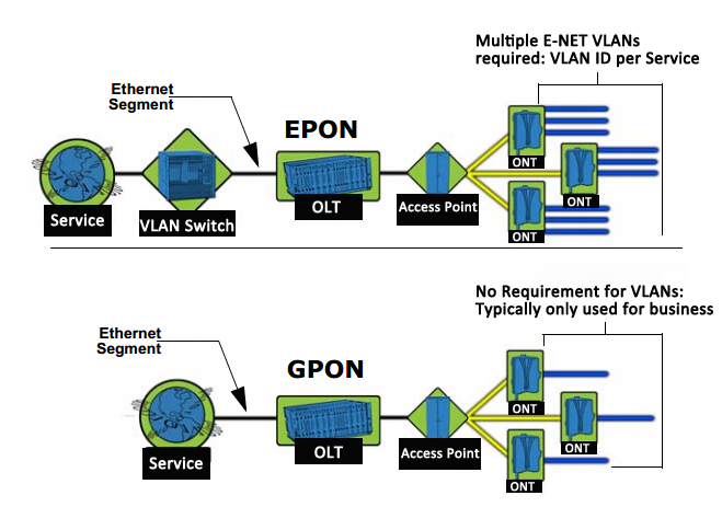
Figure 1: Campus network design

On campus cabling system, according to the classification of schools located in differnet, differnet mission, teaching different functions, as well as regional and other characteristics of different regions, each school has a different more or less cabling place. However, there are several points which can be used as colleges campus cabling system to explore the commonalities, but also can be used as a variety of colleges and universities can learn from campus cabling system solutions.
1. Campus Cabling diversity
a. Building diversity
We also mentioned earlier, in the campus, especially college a wide variety of buildings, each building its building types and architectural features may vary. Some twenty or thirty or more layers of tall buildings (such as the school’s main building, complex building, etc.), while others are one, two dwarf room (such as canteens, etc.); Some large bay, less information building (such as school gymnasium, etc.); While others are small spaces, intensive information construction (such as multimedia classrooms or computer training room, etc.). For such floor height varies, of various sizes, the number of different information points, we have to make different plans. For high rise buildings, for the convenience and savings trunk cable laying wires, equipment room locationi will need to be carefully considered, such as computer room location is set to the middle of the building. And you do not need low building special consideration. For information point-intensive construction, telecommunications room on each floor of its location also needs attention. Because if you set reasonable, we can save a lot of horizontal cable; What’s more, if too much information points in the same layer, also need to consider setting up multiple telecommunications rooms. For large bays place, not only to consider the distribution of information points, but also consider wheter there is the level of information points length over 90 meters, if there are more than 90 meters of the situation, we need to consider the use of fiber optic cable or increase between telecommunications solutions. Also, in some campus gymnasium, auditorium and other places, also need to consider whether to set CP boxes and other issues.
b. Application of diversity
In colleges and universities, the diversity of buildings, each building determines the variety of applications. Such as teachers’ apartments, student dormitories, school comprehensive building, administration building, a variety of different teaching building, laboratory building used for research, data storage and computing centers. Applications and their information needs are very different. So many applications need not buildings and places, they must be designed according to different requirements. Teachers apartments, student dormitories according to ordinary residential buildings can be cabling design; househole classroom or every student dormitory apartment, basically meet a data point, a voice can be. Comprehensive building, administration building can be carried out according to the way commercial office planning and design; In addition to meet the demand of each office’s basic data, voice, consider increasing the internal campus network information in a specific department, such as education private network information point requirements. A variety of conferentce rooms, reception and other areas, need to consider adding wireless AP points. Data storage and computing centers can be designed according to the data center, to meet a variety of information throughout the campus switching, aggregation and storage. The experimental and research laboratory building as an important place, which may have strong radiation, corrosive material existence, there may exist high temperature, humidity, shock and vibration environments, there may be the most dangerous biological virus. Therefore, their application and requirements may be much more than we usually say ten categories of construction areas, so for special programs. To take into account not only the electromagnetic interference, environmental impact, but also consider the potential life safety issues. Therefore, these sites suggest using the whole screen or fiber class industrial grade high flame retardant wiring products, such as using fire-retardant grade reach CMP / OFNP grade, industrial grade reaches IP67 cabling products.
2. High-speed transmission of information
High speed transmission of information for campus cabling system is already a pressing task. A variety of multimedia transmission, video transmission and other large flow of data communication more and more. For school on the high speed network transmission channel is essential. Including multimedia educational system, remote network education system, digital libraries, data centers and other places, is information is very concentrated, at least to ensure Gigabit to the desktop, Gigabit backbone. Under the condition of the budget allows, it is best able to do Gigabit to the desktop, 40G/100G as the backbone for future development needs. For classroom apartment or student residence, it should try to make Gigabit to the desktop requirements. Because who knows, in the next 5-10 years, or longer period of time, how fast development of the Internet? telematics what would happen to the great changes? Campus Network what will change? So in product planning, to do not only meet the existing information and communication needs, but also to do with a certain forward looking.
3. Stability and security of information
In the campus network, the reliability and security of information transmission is very important, because it not only directly related to the use of campus communications network, but also to the entire campus of internal and external education system problems. Which may affect the security of network communications to the national education system. Instability in the event of information or information leaks, not only caused the affected education, and may bring significant social problems. Such as school entrance examination system due to system instability problems, or important information or test data within the education sector was stolen during transmission and so on. So campus intranet for information requirement is in any case have to ensure that the information transmitted high reliability, high security. In the planning and design of the campus cabling must be to choose a good quality cabling products, but also in fiber optic cabling system to avoid interference or disclosure of information. Achieve stable performance, reliable transmission of information security.
The Campus Cabling System Considerations
1. Disaster preparedness
Disaster prevention, for any cabling system is need, and also is necessary. On campus cabling system, pay attention to disaster prevention and many, such as earthquakes, lightning, flood, fire, etc. Around the school to the actual situation may have different, but in the integrated wiring system, the following two disasters have a very important relationship.
a. Lightning Stroke
Campus cabling system is different from general cabling system is one of the local architecture is numerous, wide distribution. Each building and interconnection of information between, or the information architecture and data center interconnection, must pass a variety of outdoor communication cables, so the campus backbone cable corresponding increase, which gives the outdoor cabling lightning protection challenges. Because once a root trunk cable struck by lightning, and the grounding system in case of a problem or did not do, when hundreds of thousands of volts high voltage transient will pass along the cables between devices, resulting in equipment damage, data lost, resulting in significant losses. So into the line of good grounding system and surge protection is very important. Of course, if you want to achieve more secure, avoid outdoor cables in danger of being struck by lightning can also be used outdoors in all non-metallic reinforcing Outdoor Fiber Cable.
b. Fire Disaster
In addition to natural disasters, the current fire casualties and property loss is caused by the most serious disasters. On campus, most of the buildings are crowded places. In addition to selecting a variety of fire related materials and good fire prevention measures, cabling system cables fire retardant also has become essential. Because as the demand for information transmission, communications cable in the building has more than the number of number of strong electric cables trend, but the communication cable fire retardant has not been given due attention.
In addition, for campus cabling system, others, such as the computer room of the need to guard against seismic reinforcement, cables rat bite, etc., also need to pay attention.
2. Management 
For school cabling systems, too much applications, and wide distribution of information points, application and needs vary, which brought the system management and maintenance of a great test. The traditional label drawing and handwriting management, or use the computer for documentation and preservation of the way, for such a large cabling systems, it has become beyond their grasp. In particular, to achieve a change to the information point and preservation of records in a timely manner, it is very difficult. Therefore, within the scope of the budget allows, it is recommended universities such as large scale cabling system uses intelligent infrastructure management system to improve cabling system maintenance and management, and enhance network security.
3. Intelligent Building digitized

In campus intelligent cabling, in addition to our previously mentioned, but also includes the campus radio systems, fire alarm systems, electronic fence system, monitoring system, LED large screen display systems, etc. These systems are in the transition to digital. Because of a digital campus will be teaching, research, management, technical services, services life and campus information collection, processing, integration, storage, transmission and application, so that the use of digital resources are fully optimized. By implementing from the environment (including equipment, classrooms, etc.), resources (such as books, handouts, courseware, etc.) to the application (including teaching, learning, management, service, office, etc.) all digitized, in the traditional campus built on a digital space to improve the operating efficiency of the traditional campus, expanding the traditional campus business functions, and ultimately the overall educational process information, so as to improve the management level and efficiency. Therefore, the campus all variety of intelligent system based on transmission channel will also jumped to Gigabit, and even Gigabit network requirements. In the design and planning, and perhaps to consider the application of digitization. In which the product can be selected copper Cat6a Cable, cat 6a, cat 7 products, fiber optic cable in OM3 Cable and other fiber optic products. However, for fire alarm systems, campus broadcasting system, and its products should be chosen to meet the high flame retardant properties, if possible, it is best to choose a high fire retardant cables. Because it does not lead to a fire occurs due to the rapid combustion of the cable causes the system to malfunction.

Figure 2: 305m Bulk Cat6 550MHz Cable UTP

Conclusion
Campus cabling system though complex, but as long as we grasp the core features of cabling system, clear the standard cabling system the basic requirements, specifically the various buildings, the application of the various systems and functions. It is not difficult to design and planning. Even the school have dozens, hundreds buildings, even if there are many school of information and communication applications, the final analysis are inseparable from the basic principles of cabling. Therefore, cabling system in the school, in order to maximize long as we grasp little less to more of the principles from the point to the line, from a line to a plane unfold. You will find, and then a big projects, the final show in front of us or our common and often do a single type of building cabling system, just follow their individual needs and applications for planning and design, you can complete set of perfect school cabling system.

Modern 110 Connecting Blocks For Data Networking

Share

110 wiring block are one type of punch blocks used to connect sets of wires in a structured cabling system. The “110″ designation is also used to describe a type of insulation-displacement connector used to terminate twisted pair cables which uses a similar punch-down tool as the older 66 block. People are preffered to 110 blocks rather than 66 blocks in high-speed networks because they introduce less crosstalk and allow much higher density terminations, and meet higher bandwidth specifications. Many 110 blocks are certified for use in Category 5 and Category 6 wiring systems, even Category 6a. The 110 block provides an interconnection between patch panels and work area outlets.

Modern homes usually have phone service entering the house to a single 110 block, when it is distributed by on-premises wiring to outlet boxes throughout the home in series or star topology. At the outlet box, cables are punched down to standard RJ-11 sockets, which fit in special faceplates. The 110 block is often used at both ends of Category 5 cable runs through buildings. In switch rooms, 110 blocks are often built into the back of patch panels to terminate cable runs. At the other end, 110 connections may be used with keystone modules that are attached wall plates. In patch panels, the 110 blocks are built directly onto the back where they are terminated. Category 6 – 110 wiring blocks are designed to support Category 6 cabling applications as specified in TIA/EIA-568-B.2-1 with unique spacing that provides superior NEXT performance.

What is the difference between a “110 block” and a “66 block”?

Both 66 and 110 blocks are insulation displacement connection (IDC) devices, which are key to reliable data connections. 66-clip blocks have been the standard for voice connections for many years. 110 blocks are newer and are preferable for computer work, for one thing, they make it easier to preserve the twist in each pair right up to the point of connection.

1. Although 66-clip blocks historically have been used for data, they are not an acceptable connection for Category 5 or higher cabling. The 110-type connection, on the other hand, offers: higher density (more wiring in a smaller space) and better control (less movement of the wires at the connection). Since more and more homes and businesses call for both voice and data connections, it is easy to see why it makes sense to install 110-type devices in most situations. Most cat5e keystone jack also use type 110 terminals for connecting to the wire.

2. The 110 block is a back-to-back connection whereas the 66 block is a side-by-side connection. The 110 block is a smaller unit featuring a two-piece construction of a wire block and a connecting block. Wires are fed into the block from the front, as opposed to the side entry on the 66 block. This helps to reduce the space requirements of the 110 block and reduce overall cost. The 110 block’s construction also provides a quiet front, meaning there is insulation both above and around the contacts. Since the quiet front is lacking on the 66 blocks, a cover is often recommended.

3. 110 blocks have a far superior labeling system that not only snaps into place but is erasable. This is particularly important for post-installation testing and maintenance procedures.

Wiring block enables you to quickly organize and interconnect phone lines and communication cable, preserve the twists in each pair right up to the connection point. Plus, most networking cable equipment also use 110 type terminals for cable connections.

Overview The Ethernet Technology

Share

The term Ethernet in basic terms is cables linked to a network which in-turn send data packets across several networks. Ethernet works by linking computers and other devices through cables. One end of these cables is connected to the computer, and the other is to a connector. These Fiber Connectors could be Repeaters, Hubs or fiber switch.

In the present, the Ethernet technology is available in many versions. The earliest ones are the 10BASE5 (the very first standard), 10BROAD36 (the first standard that allowed long-distance connections), 10BASE2 (also known as the Cheapernet) and 1BASE5 (said to be a failure but started the following developments in Ethernet technology).

The more modernized generation of the technology came with different speed performances. The 10 megabit Ethernet was the first to step out of the previous 1Mbit/second rating. And then the Fast Ethernet, which upholds the rate of 100Mbit per second, dethroned the previous by executing ten times higher.

And then the Gigabit Ethernet was born, priding itself with an even more edgy speed of 1 gigabyte per second data transmission. The Gigabit Ethernet soon opened doors for the 10 Gigabit Ethernet, the variant that surpassed its already-powerful precedent. And today, the public is only waiting for newer versions 40 and 100 Gigabit to be released.

Some Ethernet knowledge you must know. The 10 Mbps protocol continues to be most widely used for most networks, and commonly regarded as ‘Standard Ethernet’ as well as 10BASE-T. Many networks are currently making use of something known as the ‘Fast Ethernet’ which uses a 100 Mbps protocol and is known as 100BASE-T. Finally you will find the 1000 Mbps protocol which is referred to as the ‘Gigabit Ethernet’. Most LAN systems at present use a Fast Ethernet for the main system, and every one of the computer workstations will use particular 100BASE-T or 10BASE-T ethernet card which the LAN facilitates.

The Ethernet is classified making use of international standards, explicitly IEEE 802.3. It makes it possible for the connection of fiber optic cables, up to 1024 coaxial nodes and the twisted-pair cable and the most often used is the Category 5 cable.

The Ethernet functions in such a way that signals are transmitted serially from the primary location to all locations within the network. The Ethernet will make use of a CSMA/CD Carrier Sense Multiple Access/Collision Detection. This implies that all locations will hear all transmissions but is only to listen to the ones that have been meant for it.

Depending on the size your network you are able to select Standard, Fast or GigaByte Ethernet setups. Obviously, the bigger the network the higher the Ethernet setup you need to utilize. If you use the Standard Network but have hundreds of workstations on the network, it may not be able to handle all the transmissions and can have too many collisions which will decelerate everything. Want to have some products to support your Ethernet, like serial to ethernet, ethernet card,ethernet Media Converter and so on. FiberStore maybe can help you.

Many newer versions of Ethernet are updated often as the necessity for more performance primarily based services becomes imperative. The wants of organisations differ and thus does the dimensions of the network. The value for putting in place an Ethernet network depends upon the quantity of computers that is to be connected on the network. The computers therefore connected through the Ethernet network can share a common operating system, security measures and unique identification certificates. It uses special routers, switch or modems for this according to the need or necessity. It wants minimal hardware and that is principally Ethernet cables to connect. It will be used for both wired and wireless interfaces. Even for personal use one will founded the Ethernet affiliation to attach a pair of-three computers among the same home network. Thus it is extremely helpful to form a standard communication network within an area. Knowing what ethernet communications are will be terribly helpful to all technocrats and even the laymen as everyone is using computers at home and within the office.