What is Core Layer?
The Core Layer in networking serves as the backbone of a hierarchical network design, forming a critical component within the three-layer model alongside the Access and Distribution layers. Situated at the center of network architecture, the Core Layer is designed for high-speed, high-capacity packet switching, ensuring swift and efficient transport of data across the entire network.
Unlike the Distribution Layer, the Core Layer typically focuses on rapid data transfer without applying extensive processing or policy-based decision-making. Its primary objective is to facilitate seamless and fast communication between different parts of the network.
Duty of Core Switches
In the enterprise hierarchical network design, the core layer switch is the topside one, which is relied on by the other access and distribution layers. It aggregates all the traffic flows from distribution layer devices and access layer devices, and sometimes core switches need to deal with external traffic from other egresses devices. So it is important for core switches to send large amounts of packets as much as possible. The core layer always consists of high-speed switches and routers optimized for performance and availability.
Located at the core layer of enterprise networking, a core layer switch functions as a backbone switch for LAN access and centralizes multiple aggregation devices to the core. In these three layers, core switches require most highly in the switch performance. They are usually the most powerful, in terms of forwarding large amounts of data quickly. For most of the cases, core switches manage high-speed connections, such as 10G Ethernet, 40G Ethernet or 100G Ethernet. To ensure high-speed traffic transfer, core switches should not perform any packet manipulation such as Inter-Vlan routing, Access Lists, etc., which are performed by distribution devices.
Note: In small networks, it is often the case to implement a collapsed core layer, combining the core layer and the distribution layer into one as well as the switches. More information about the collapsed core is available in How to Choose the Right Distribution Switch?
Factors to Consider When Choosing Core Switches for Enterprises
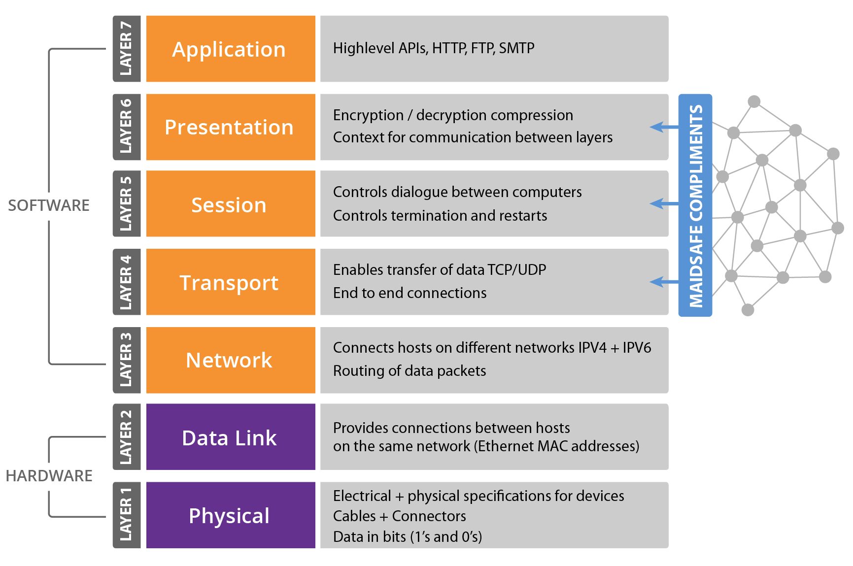
Simply put, core layer switches are generally layer 3 switches with high performance, availability, reliability, and scalability. Except for considering the basic specifications like port speed and port types, the following factors should be considered when choosing core switches for an enterprise network design.
Performance
The packet forwarding rate and switching capacity matter a lot to the core switch in enterprise networking. Compared with the access layer switches and distribution switches, core switches must provide the highest forwarding rate and switching capacity as much as possible. The concrete forwarding rate largely depends on the number of devices in the network, the core switches can be selected from the bottom to the top based on the distribution layer devices.
For instance, network designers can determine the necessary forwarding rate of core switches by checking and examining the various traffic flow from the access and distribution layers, then identify one or more appropriate core switches for the network.
Redundancy
Core switches pay more attention to redundancy compared with other switches. Since the core layer switches carry much higher workloads than the access switches and distribution switches, they are generally hotter than the switches in the other two layers, the cooling system should be taken into consideration. As often the case, core layer switches are generally equipped with redundant cooling systems to help the switches cooling down while they are running.
The redundant power supply is another feature that should be considered. Imagine that the switches lose power when the networking is running, the whole network would shut down when you are going to perform a hardware replacement. With redundant power supplies, when one supply fails, the other one will instantly start running, ensuring the whole network unaffected by the maintenance.
FS provides switches with hot-swappable fans and power supply modules for better redundancy.
Reliability
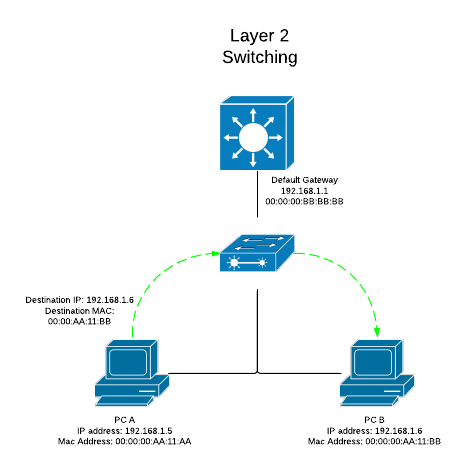
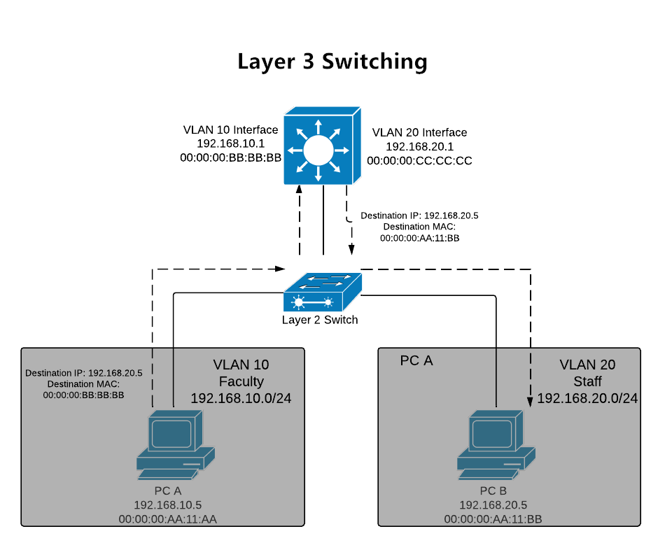
Typically core switches are layer 3 switches, performing both switching and routing functions. Connectivity between a distribution and core switches is accomplished using layer 3 links. Core switches should perform advanced DDoS protection using layer 3 protocols to increase security and reliability. Link aggregation is needed in core switches, ensuring distribution switches delivering network traffic to the core layer as efficiently as possible.
Moreover, fault tolerance is an issue to consider. If a failure occurs in the core layer switches, every user would be affected. Configurations such as access lists and packet filtering should be avoided in case that network traffic would slow down. Fault-tolerant protocols such as VRRP and HSRP is also available to group the devices into a virtual one and ensure the communication reliability in case one physical switch breaks down. What’s more, when there are more than one core switches in some enterprise networks, the core switches need to support functions such as MLAG to ensure the operation of the whole link if a core switch fails.
QoS Capability
QoS is an essential service that can be desired for certain types of network traffic. In today’s enterprises, with the growing amount of data traffic, more and more voice and video data are required. What if network congestion occurs in the enterprise core? The QoS service will make sense.
With the QoS capability, core switches are able to provide different bandwidth to different applications according to their various characteristics. Compared with the traffic that is not so sensitive about time such as E-mail, critical traffic sensitive to time should receive higher QoS guarantees so that more important traffic can pass first, with the high forwarding of data and low package loss guaranteed.
As you can see from the contents above, there are many factors that determine what enterprise core switches are most suitable for your network environment. In addition, you may need a few conversations with the switch vendors and know what specific features and services they can provide so as to make a wise choice.
Related Articles: