Author Archives: Chloe Wang

What Is Network Edge?

Share

The concept of the network edge has gained prominence with the rise of edge computing, which involves processing data closer to the source of data generation rather than relying solely on centralized cloud servers. This approach can reduce latency, improve efficiency, and enhance the overall performance of applications and services. In this article, we’ll introduce what the network edge is, explore how it differs from edge computing, and describe the benefits that network edge brings to enterprise data environments.

What is Network Edge?

At its essence, the network edge represents the outer periphery of a network. It’s the gateway where end-user devices, local networks, and peripheral devices connect to the broader infrastructure, such as the internet. It’s the point at which a user or device accesses the network or the point where data leaves the network to reach its destination. the network edge is the boundary between a local network and the broader network infrastructure, and it plays a crucial role in data transmission and connectivity, especially in the context of emerging technologies like edge computing.

What is Edge Computing and How Does It Differ from Network Edge?

The terms “network edge” and “edge computing” are related concepts, but they refer to different aspects of the technology landscape.

What is Edge Computing?

Edge computing is a distributed computing paradigm that involves processing data near the source of data generation rather than relying on a centralized cloud-based system. In traditional computing architectures, data is typically sent to a centralized data center or cloud for processing and analysis. However, with edge computing, the processing is performed closer to the “edge” of the network, where the data is generated. Edge computing complements traditional cloud computing by extending computational capabilities to the edge of the network, offering a more distributed and responsive infrastructure.


” Also Check – What Is Edge Computing?


What is the Difference Between Edge Computing and Network Edge?

While the network edge and edge computing share a proximity in their focus on the periphery of the network, they address distinct aspects of the technological landscape. The network edge is primarily concerned with connectivity and access, and it doesn’t specifically imply data processing or computation. Edge computing often leverages the network edge to achieve distributed computing, low-latency processing and efficient utilization of resources for tasks such as data analysis, decision-making, and real-time response.
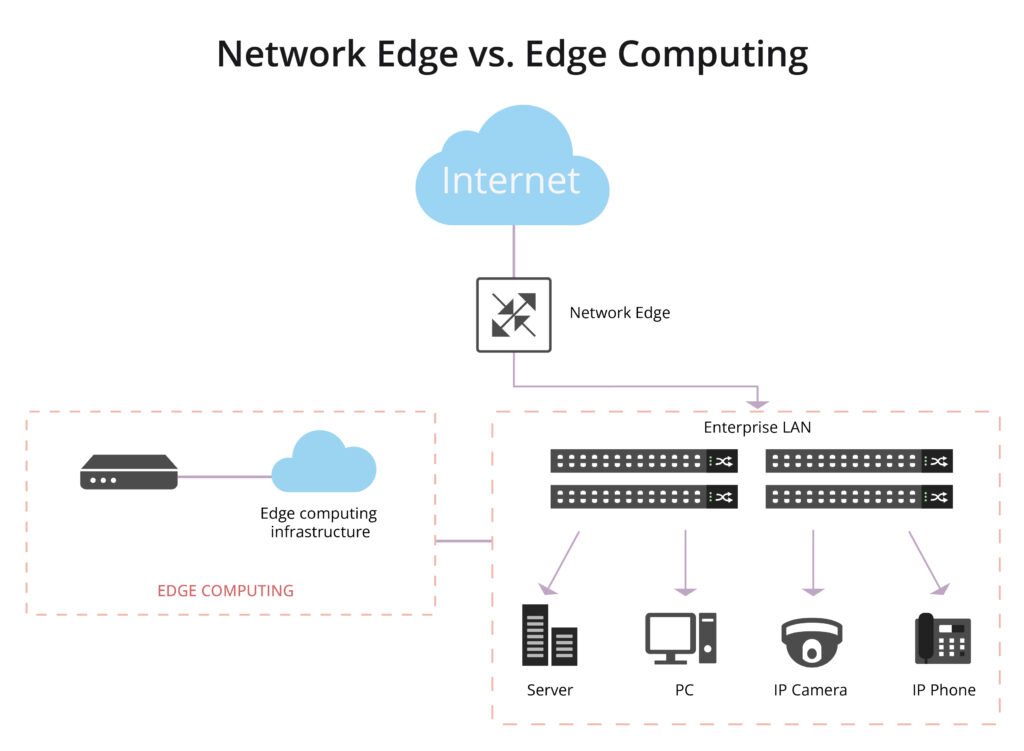
Network Edge vs. Edge Computing

Network Edge vs. Network Core: What’s the Difference?

Another common source of confusion is discerning the difference between the network edge and the network core.

What is Network Core?

The network core, also known as the backbone network, is the central part of a telecommunications network that provides the primary pathway for data traffic. It serves as the main infrastructure for transmitting data between different network segments, such as from one city to another or between major data centers. The network core is responsible for long-distance, high-capacity data transport, ensuring that information can flow efficiently across the entire network.

What is the Difference between the Network Edge and the Network Core?

The network edge is where end-users and local networks connect to the broader infrastructure, and edge computing involves processing data closer to the source, the network core is the backbone that facilitates the long-distance transmission of data between different edges, locations, or network segments. It is a critical component in the architecture of large-scale telecommunications and internet systems.

Advantages of Network Edge in Enterprise Data Environments

Let’s turn our attention to the practical implications of edge networking in enterprise data environments.

Efficient IoT Deployments

In the realm of the Internet of Things (IoT), where devices generate copious amounts of data, edge networking shines. It optimizes the processing of IoT data locally, reducing the load on central servers and improving overall efficiency.

Improved Application Performance

Edge networking enhances the performance of applications by processing data closer to the point of use. This results in faster application response times, contributing to improved user satisfaction and productivity.

Enhanced Reliability

Edge networks are designed for resilience. Even if connectivity to the central cloud is lost, local processing and communication at the edge can continue to operate independently, ensuring continuous availability of critical services.

Reduced Network Costs

Local processing in edge networks diminishes the need for transmitting large volumes of data over the network. This not only optimizes bandwidth usage but also contributes to cost savings in network infrastructure.

Privacy and Security

Some sensitive data can be processed locally at the edge, addressing privacy and security concerns by minimizing the transmission of sensitive information over the network. Improved data privacy and security compliance, especially in industries with stringent regulations.

In this era of digital transformation, the network edge stands as a gateway to a more connected, efficient, and responsive future.


Related Articles:

How Does Edge Switch Make an Importance in Edge Network?

Best Gigabit Switches to Set up Your Home Network

Share

If you expect to provide your devices with a wired internet connection that is faster and more stable but your router only has a few Ethernet ports, you should get the best gigabit switch for your home network. When you use one of the best network switches, you can add more ports to your network, allowing you to connect more devices than you could with the router’s few built-in ports. You can compare and choose from the best gigabit switches for your home network in this article.

Key Features of the Gigabit Switch

Gigabit switch, called the 1G switch, helps increase home network speeds, typically supporting copper speeds of 10/100/1000 Mbps and fiber optic speeds of 1000 Mbps. The following are some features of gigabit switches:

  • Gigabit switches have varying numbers of ports, from 2 to 50 or more.
  • From the point of view of port design, there are two types, namely gigabit Ethernet switch and fiber gigabit switch. Ethernet switches can transmit data quickly, while SFP fiber switches can transmit longer distances.
  • Gigabit switches are also classified as managed or unmanaged switches, which means that the former can operate in automatic mode, while the latter must be programmed manually.
  • Most desktop switches feature a simple plug-and-play design, making them easy to operate.
  • Gigabit switches can implement half-duplex and full-duplex modes in terms of traffic in single-mode and multi-mode network environments.
  • These switches will have many LED indicators that indicate various parameters such as port type, status, link, activity, etc.

”Also Check- Gigabit Switch

What You Can Expect From Your Home Network

Influenced by several years of COVID-19, people are more and more working from home, so we pay more and more attention to home networks. Today, with the rapid development of high-speed communications, the demand for home networks is even stronger, because even if residents do not work at home, they still want to share high-speed networks at home.The requirements for Gigabit Ethernet in the home network usually have the following points:

  • Increased efficiency in media sharing
  • Fluency of office network
  • Supports HD video calling and conferencing
  • Unlimited upload and download speed

A Better Gigabit Switch For Your Home Network

Here are several aspects to consider when choosing a Gigabit switch. You can determine the type of switch you need based on the characteristics of the switch and your personal requirements.

Number of ports

Checking the number of ports it comes with is one of the most important things you can do to help you choose a great gigabit switch for your home network. You don’t want to buy a device that doesn’t solve this problem because one of the reasons you’re spending money on an Ethernet switch is to get more ports for your devices.The switches provide a variety of port configurations, ranging from 5 to 28, making it simple to select the model that best suits your requirements. For example, FS S3900-48T6S-R has 48 RJ45 ports, built-in dual redundant power supply and dual fans, with higher ease of use, highly secure business operation, sustainability and borderless network experience.


”Also Check- FS S3900-48T6S-R Switch

FS Switch

PoE vs Non-PoE Switches

Gigabit Power over Ethernet (PoE) gigabit switches connect devices to data and DC power. These are very useful for connecting powered network equipment to the network, as only one cable is required to connect to the equipment. You can effectively avoid home network failures by using a managed PoE switch to remotely restart connected devices by turning off and on the Ethernet port’s power.A gigabit non-PoE switch that only provides network connectivity but does not supply DC power to connected devices. When there are a lot of non-powered network devices, like PCs and laptops, on the network, these switches are a good choice.

Managed vs Non-managed Switches

Managed gigabit switches are more secure and can either separate portions of your network into their own virtual local area networks (VLANs) or monitor traffic for troubleshooting purposes. If you decide to use this type of switch, you should also check that your switch is compatible with VLANs. For instance, a setup that does not use a bridge and uses Amazon’s eero mesh routers renders VLANs useless.Unmanaged network switches are what we recommend for most users if you only need wired internet access to a few devices. This does not imply that the switch lacks features; unmanaged switches frequently possess a wide range of sophisticated capabilities, such as loop detection and traffic prioritization QoS.

Fan vs Fanless Switches

The active cooling system used by the built-in fan switch is a type of cooling technology that uses an external device to improve heat transfer. During convection, an active cooling system means that the rate of fluid flow increases, significantly increasing the rate at which heat is removed.A fanless switch operates quietly because it does not have a fan built in. Utilizing a heat spreader or heat sink to maximize the radiation and convection heat transfer modes, the passive cooling system achieves a high level of natural convection and heat dissipation.

Conclusion

Gigabit switches are the most widely used and can save energy in home networks. It is wise to choose a managed or unmanaged Gigabit switch with copper and fiber port modules as it makes it easy to expand the network in the future or even add devices in the short term. FS offers a wide range of Gigabit Ethernet switches with RJ45 and SFP ports compatible with a wide range of devices and copper and fiber optic networks, most of which also support PoE.

Related article:

Home Ethernet Wiring Guide: How to Get a Wired Home Network?

How to Choose the Best 10 Gigabit Switch for Home?

FAQs About FS 400G Transceivers

Share

FS 400G transceivers offer customers a wide variety of super high-density 400 Gigabit Ethernet connectivity options for data centers, enterprise networks, and service provider applications. Here is a list of FAQs about our new generation of 400G transceiver modules.

Q: What 400G transceivers are available from FS?

A: FS supports a full range of 400G optical transceivers in both OSFP and QSFP-DD form factors, 400G AOCs and DACs, and 400G breakout cables. The tables below summarize the 400G connectivity options FS supports.

CategoryProductMax Cable DistanceConnectorMediaPower Consumption
400G Transceivers400G QSFP-DD SR870m@OM3/100m@OM4MTP/MPO-16 (APC)MMF≤10W
400G QSFP-DD DR4500mMTP/MPO-12 (APC)SMF≤10W
400G QSFP-DD XDR42kmMTP/MPO-12SMF≤12W
400G QSFP-DD FR42kmDuplex LCSMF≤12W
400G QSFP-DD LR410kmDuplex LCSMF≤12W
400G QSFP-DD PLR410kmMTP/MPO-12SMF≤10W
400G QSFP-DD LR810kmDuplex LCSMF≤14W
400G QSFP-DD ER840kmDuplex LCSMF≤14W
400G OSFP SR8100mMTP/MPO-16MMF≤12W
400G OSFP DR4500mMTP/MPO-12 (APC)SMF≤10W
400G Cables400G QSFP-DD DAC/AOC100mQSFP-DD/≤11W
400G Breakout DAC/AOC30mQSFP-DD to 2x QSFP56, QSFP-DD to 4x QSFP56, QSFP-DD to 4x QSFP28, QSFP-DD to 8x SFP56/≤11W

Q: What are the benefits that FS 400G transceivers can offer?

A: FS 400G transceivers help cloud operators, service providers, and enterprises to achieve higher bandwidth at lower cost and power per gigabit. Key benefits of FS 400G transceivers include:

  • With both OSFP and QSFP-DD form factors to meet your diverse needs of ramping up to 400G transmission.
  • SiPh-based technology used on some FS 400G transceivers for lower power & cost and higher density.
  • Compliant with QSFP-DD MSA and IEEE 802.3bs, and tested in host devices for proven interoperability, superior performance, quality, and reliability.
  • Compatible with mainstream brands such as Cisco, Juniper, Arista, Dell, Mellanox, etc.
  • Simplify your network by reducing the number of optical fiber links, connectors and patch panels by a factor of 4.

Q: What are the application scenarios of FS 400G transceivers?

A: 400G QSFP-DD transceiver modules are the backbone of high-performance 400G networks. FS 400G transceivers can be used in various scenarios. Generally speaking, it depends on the connection distance you want to cover. For example, you can use 400G DAC and AOC cables for short-reach connections between ToR switch and server. For 2km to 10km data center interconnection connections, QSFP-DD FR4 or LR4 modules are better high-quality and economical choices.

Q: What quality certifications do you have for your 400G transceivers?

A: FS 400G transceivers accord with a range of certifications for optical transceivers including ISO 9001:2015, RoHS, REACH, CB, RCM, FCC, and Russian TR CU certificate (EAC Certificate). Rest assured that our products will meet essential quality and safety requirements.

Q: Are FS 400G transceivers compatible with Cisco or Juniper brands?

A: Many of our 400G transceiver modules are compatible with Cisco, Juniper, Arista, Dell, Mellanox, etc. You can always ask for a compatibility test before the purchase to check whether our transceiver is compatible with your devices. If you’re deploying a larger network or upgrading your current data center architecture, compatible transceiver modules may come in handy as they can be immediately installed without compatibility problems and fit right into your data center infrastructure.

Q: Can I plug FS OSFP module into a 400G QSFP-DD port, or FS QSFP-DD module into an OSFP port?

A: No. OSFP and QSFP-DD are two physically distinct form factors. If you have an OSFP system, then FS 400G OSFP modules must be used. If you have a QSFP-DD system, then FS 400G QSFP-DD modules must be used.

Q: Can FS 100G QSFP module be plugged into a 400G QSFP-DD port?

A: Yes. A 40/100GQSFP transceiver module can be inserted into a QSFP-DD port as QSFP-DD is backward compatible with QSFP, QSFP+, and QSFP28 transceiver modules. When using a QSFP module in a 400G QSFP-DD port, the QSFP-DD port must be configured for a data rate of 100G.

Q: What should I do if I don’t know which transceiver module is the right one for me?

A: Our dedicated customer support offers 24/7 technical assistance. If you have any questions about our transceiver modules, such as how to select the right 400G optical transceiver for your switches, how to choose between different form factors, what to do when typical technical glitches occur, or how to place an order, don’t hesitate to contact our tech support.

Q: Can I return the product or get a refund?

A: FS wants you to be thrilled with our 400G transceiver modules. However, if you need to return an item or ask to get a refund, we’re here to help. For all 400G transceiver modules, DAC & AOC cables, and breakout cables, you have 30 calendar days to return an item from the date you received it, which means the request must be submitted within the return/exchange window. Refunds will be processed after FS receives and inspects the returned items.

Q: How long is the warranty period for FS 400G transceivers?

A: We offer you a warranty period of five years for the purchase of 400G transceiver modules, DAC & AOC cables, and breakout cables. The warranty covers only defects arising under normal use and does not include malfunctions or failures resulting from misuse, abuse, neglect, alteration, problems with electrical power, usage not in accordance with product instructions, acts of nature, or improper installation or improper operation or repairs made by anyone other than FS or an FS authorized service provider. Please check FS Products Warranty for detailed info.

If you have any questions about FS 400G transceiver modules, you can always Contact Us for assistance.

Article Source

https://community.fs.com/news/faqs-about-fs-400g-transceivers.html

Related Articles

FAQs on 400G Transceivers and Cables

How Many 400G Transceiver Types Are in the Market?

Basics about 400G DAC and 400G AOC

Share

Data centers, enterprises, and high-performance computing environments require flexible and well-defined 50G, 100G, 200G, and 400G direct attach cables for interconnection within a rack or between adjacent racks. With the development of 400G technology, 400G direct attach cables for short-distance DCI (Data Center Interconnect) have been mass-produced and put into market, which includes 400G DAC and 400G AOC.

Main Types of 400G DAC & AOC in the Market

Either 400G DAC or 400G AOC comes with two main form factors: QSFP-DD and OSFP, both of which can carry 8x50Gb/s PAM4 electrical lanes. Besides, there are also 400G breakout DAC/AOCs, with one 400G connector at one end, and several same connectors whose total rate is 400G at the other end. The table below shows the main types of 400G DAC /AOC and the 400G breakout DAC/AOCs in the market.

CatagoryNameProduct DescriptionReachApplication
400G QSFP-DD DACQSFP-DD to QSFP-DD DACwith each 400G QSFP-DD using 8x 50G PAM4 electrical lanesno more than 3m400G network direct connection
400G QSFP-DD Breakout DACQSFP-DD to 2x 200G QSFP56 DACwith each 200G QSFP56 using 4x 50G PAM4 electrical lanesno more than 3m400G to 200G network connection
QSFP-DD to 4x 100G QSFPs DACwith each 100G QSFPs using 2x 50G PAM4 electrical lanesno more than 3m400G to 100G network connection
QSFP-DD to 8x 50G SFP56 DACwith each 50G SFP56 using 1x 50G PAM4 electrical laneno more than 3m400G to 50G network connection
400G QSFP-DD AOCQSFP-DD to QSFP-DD AOCwith each 400G QSFP-DD using 8x 50G PAM4 electrical lanes70m (OM3) or 100m (OM4)400G network direct connection
400G QSFP-DD Breakout AOCQSFP-DD to 2x 200G QSFP56 AOCwith each 200G QSFP56 using 4X 50G PAM4 electrical lane70m (OM3) or 100m (OM4)400G to 200G network connection
QSFP-DD to 8x 50G SFP56 AOCwith each 50G SFP56 using 1x 50G PAM4 electrical lane70m (OM3) or 100m (OM4)400G to 50G network connection
400G OSFP DACOSFP to OSFP DACwith each 400G OSFP using 8x 50G PAM4 electrical lanesno more than 3m400G network direct connection
400G OSFP Breakout DACOSFP to 2x 200G QSFP56 DACwith each 200G QSFP56 using 4x 50G PAM4 electrical lanesno more than 3m400G to 200G network connection
OSFP to 4x100G QSFPs DACwith each 100G QSFPs using 2x 50G PAM4 electrical lanesno more than 3m400G to 100G network connection
OSFP to 8x 50G SFP56 DACwith each 50G SFP56 using 1x 50G PAM4 electrical laneno more than 3m400G to 50G network connection
400G OSFP AOCOSFP to OSFP AOCwith each 400G OSFP using 8x 50G PAM4 electrical lanes70m (OM3) or 100m (OM4)400G network direct connection

Differences Between 400G DAC and 400G AOC

According to the table, we know that the main differences between 400G DAC and 400G AOC are transmission distance and the available types on the market. At present, 400G DAC can provide more breakout cables and better satisfy your different connection requirements. Apart from that, 400G DAC and AOC differ from each other in the following aspects.

  • Weight and volume – With fiber optic cable as transmission media, 400G AOC has about half the volume and only a quarter the weight of 400G copper DAC. Also, its cable bending radius is smaller than 400G DAC.
  • Interference-resistance – Since 400G AOC with fiber optic cable doesn’t conduct electrical currents, it is resistant to interference from electromagnetic, lightning, or radio signals during data transmission. While 400G DAC with copper cable is vulnerable to power lines, lightning, and signal-scrambling.
  • Price – On today’s 400GbE cable market, the price of the 400G AOC is often higher than that of 400G DAC, of course, with the same level. If both of them can meet your needs, you can choose a 400G DAC to save costs.

Further Consideration about 400G DAC and 400G AOC

Both 400G DAC and AOC are cost-effective solutions for short-distance transmission. When it comes to the transmission over 100m, 400G optical transceivers combined with the matched fiber optic cables are a suitable solution. In today’s market, 400G QSFP-DD/OSFP transceivers are continuously being pushed to the market and gradually realize mass production. So, what are 400G QSFP-DD/OSFP transceiver types and what fiber optic cables could be used with these 400G optical modules? Continue reading to find the answers in the two articles: 400G OSFP Transceiver Types Overview400G QSFP-DD Transceiver Types Overview.

FAQ about 400G DAC/AOC

Q: Why does 400G DAC/AOC adopt PAM4 modulation?

A: PAM4 is a more efficient modulation technology that can effectively improve the bandwidth utilization efficiency. With same Baud rate, PAM4 signal can transmit twice faster than the traditional NRZ signal. Also, the transmission costs are greatly reduced.

Q: What’s the key technology of 400G DAC/AOC?

A: The core technologies of 400G DAC/AOC are PAM4 and DSP. Since PAM4 is more sensitive to noise than NRZ especially in 400G AOC, DSP is introduced to make up for the disadvantage of PAM4. As a high-speed digital processing chip, DSP not only owns the function of recovering signal provided by the traditional CDR but also can make dispersion compensation and remove noise, nonlinear disturbance as well as other interferences.

FS 400G DAC Cables
Article Source

https://community.fs.com/blog/400g-direct-attach-cables-dac-and-aoc-overview.html

Related Articles

https://community.fs.com/blog/400g-transceiver-dac-or-aoc-how-to-choose.html

https://community.fs.com/news/fs-400g-cabling-solutions-dac-aoc-and-fiber-cabling.html

PAM4 in 400G Ethernet application and solutions

Share

400G PAM4 (4 Pulse Amplitude Modulation) is the modulation technology that fits for high-speed signal interconnection in the next-generation data center, paving the way to 400G Ethernet in data centers. What is 400G PAM4? Why is it chosen to be applied to 400G Ethernet? Find answers here.

What Is PAM4 for 400G Ethernet?

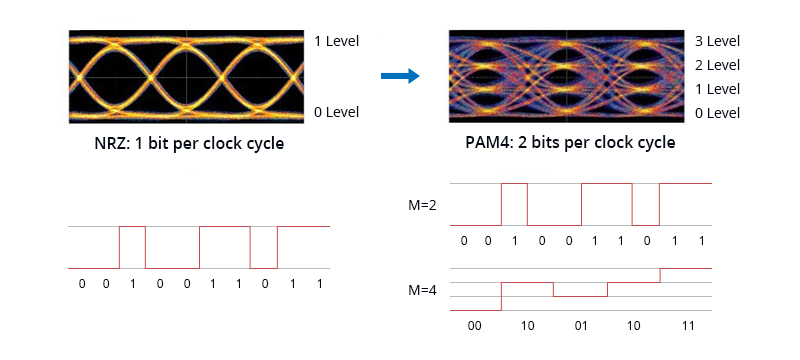
Pulse Amplitude Modulation 4-level (PAM4) is a technology that uses four different signal levels for signal transmission and each symbol period represents 2 bits of logic information (0, 1, 2, 3). By transmitting two bits in one symbol slot, PAM4 halves the signal bandwidth. Therefore, it is feasible to increase bandwidth by using advanced modulation PAM4 technology to increase the data rate without having to configure the data center with more fibers. 400 Gbps Ethernet can be realized with four lanes of PAM4 (8× 50 Gbps). This effectively doubles a network’s data rate, enabling 400G PAM4 for short-haul and long-haul transmission.

Why Does 400G Ethernet Need to Use PAM4 Technology?

In terms of supporting 400G Ethernet speed, the transmission rate of NRZ 25Gbps single channel has reached its limit, which cannot be adapted to the development of current high-density data centers. When discussing the 400GE IEEE 802.3bs standard, it was proposed to replace NRZ with PAM4 technology. So why is 400G PAM4 technology a viable alternative to NRZ?

Benefits of 400G PAM4

PAM4 modulation replaces 400G Ethernet using 16×25G baud rate NRZ and provides a path from 100G Ethernet using 4×25G baud rate to 400G Ethernet through 8×25G baud rate architecture. It is called 400G Ethernet The link adopts the 8×50G bit rate solution, reducing not only the fiber cost but also the link loss. For hyper-scale data centers, it’s time for them to transition from the previous 100G or Gigabit networks to 400G PAM4 Ethernet for faster transmission efficiency..

Compared to the NRZ signal, PAM4 has some better advantages. PAM4 carries 2 bits per symbol and transmits twice the NRZ information per symbol period. Hence, PAM4 doubles the bit rate for a given baud, thereby bringing higher efficiency to 400G transmission with greatly reduced signal loss. This key benefit of PAM4 allows existing channels and interconnects to be used at higher bit rates without doubling the baud rate and increasing channel loss..

PAM4 vs NRZ

Some information about the specific differences between PAM4 and NRZ. NRZ signaling uses two signal levels in which positive voltage defines bit 1 and the zero voltage defines bit 0. 1 bit signal is transmitted during a clock cycle.

PAM4 vs NRZ

Figure: PAM4 vs NRZ

Double Bit Rate – PAM4 doubles the bit rate for a given baud rate over NRZ. Thus, a 28 Gbaud PAM4 signal can deliver the same bit rate as a 56 Gbaud NRZ signal.

Less Signal Loss – PAM4 should let you develop 56 Gbps data lanes with less signal loss than would occur by simply doubling the NRZ (sometimes called NRZ-PAM2) bit rate. Exotic PCB materials can compensate for the deficiencies, but at a cost few are willing to pay.

400G PAM4 Transceivers: Multi-mode vs Singlemode

The 400G QSFP-DD transceivers modulation method uses PAM4 technology, including multi-mode and single-mode. In addition, the electrical port side of the 400G optical module supports 8x50G PAM4 modulation, and the optical port side supports both 8x50G PAM4 and 4x100G PAM4 modulation.

Both 400G SR8 and 400G SR4.2 multimode optical modules support 8x50G PAM4. 400G SR8 optical modules can use MPO-16 connectors or MPO-24 connectors to connect 8 pairs of fibers. The 400G SR4.2 modules use MPO-12 connectors, and the wavelengths are bidirectional and multiplexed.

According to the above mentioned, in the single-mode 400G optical module, the electrical port side is modulated with 4x100G PAM4, and a group of the optical port side is modulated with 8x50G PAM4. There are three common 8x50G PAM4 400G optical modules: FR8, LR8, and 2xFR4. 400G FR8 and 400G LR8 are the earliest available 400G single-mode interfaces, 8 wavelengths are multiplexed into one fiber, and duplex LC light is used at the same time. interface. The 2xFR4 400G optical module uses 8 lasers but is divided into two groups of 4 wavelengths according to the 200G FR4 standard.

400G optical modules modulated by 4x100G PAM4 are the focus of the current market, including 400G DR4, 400G FR4, and LR4, and their line-side uses four channels of 100G PAM4. In the 400G DR4 optical module, the DSP converts the 8x50G PAM4 electrical signal into 4x100G PAM4 and then transmits it to the optical engine.

Transceiver Solution Based on 400G PAM4

PAM4 is a relatively low-cost solution for 400GbE and data centers that has been adopted by the transceiver industry, enabling high-speed data rates, moving toward 400G and beyond. FS 400G transceivers apply 4×100G PAM4 or 8×50G PAM4 technology, which have been standardized by the IEEE working group, including 400GBASE-SR8, DR4, LR8, ER8, XDR4, FR4, and LR4. The FS 400G transceivers use a pluggable double-density design to support transmission requirements of different distances. At the same time, they can perform signal conversion through PAM4, and use multiplexing technology to convert transmission channels to achieve reasonable distribution of data center fiber resources.

StandardTransceiver TypesLink DistanceMedia TypeLanesPower Consumption
IEEE P802.3cm400GBASE-SR8100mMMF8× 50G PAM4<10W
IEEE 802.3bs400GBASE-DR4500mSMF4× 100G PAM4<10W
400GBASE-LR810kmSMF8× 50G PAM4<14W
IEEE P802.3cn400GBASE-ER840kmSMF8× 50G PAM4<14W
100G Lambda MSA400GBASE-XDR42kmSMF8× 50G PAM4<12W
400GBASE-FR42kmSMF4× 100G PAM4<12W
400GBASE-LR410kmSMF4× 100G PAM4<12W

Conclusion

As the market moves to PAM4-based modulation, more and more chip makers and transceiver vendors are manufacturing new 400G products using PAM4, transferring 400G PAM4 from theory to practice. PAM4 400G based on 50G PAM4 or 100G PAM4 will certainly become the basic rate of the next-generation Ethernet and stand out with its high performance and potential.

Article Source

https://community.fs.com/blog/pam4-for-400g-ethernet-applications.html

Related Articles

https://community.fs.com/blog/nrz-vs-pam4-modulation-techniques.html

https://community.fs.com/blog/400g-ethernet-400g-transceiver.html

How Many 400G Transceiver Types Are in the Market?

Share

With the tremendous requirement for high bandwidth in 5G, loT and cloud data center, the focus of 400G Ethernet has been lasting for a couple of years. Vendors such as Cisco, Arista, and juniper are developing and testing technologies for 400G Ethernet networks. As the key hardware devices for interconnecting optical networks, there is no dispute that 400G transceiver will become the mainstream of the industry. Still curious about 400G transceivers? This paper will give you a comprehensive introduction to the different 400G transceiver types of different characteristics including applications, interface standards, and form factors.

Transceiver Application

According to the transceiver application, optical modules can be classified into two categories: client-side transceivers and line-side transceivers.

400G Ethernet Transceivers for Client Side Transmission

Client-side transceivers are used to interconnect between the metro networks and the optical backbone. The term “client side” refers to relatively short distances compared with the line side, generally from 50m to 10km and with only one transceiver connected to fiber thus no coherent optics is needed. There are various transceiver interfaces that have been standardized by IEEE and MSA. Most importantly, it has an agreed and standardized interface that is used for the network connection. PAM4 has been chosen by IEEE 802.3bs for 400GE client side transmission.

400G Coherent Transceivers for Line Side Transmission

Different from client side, line side reaches transmission distances of 80km or even longer using DWDM. Coherent technology is expected to implement 400G line side transmission. OIF has been working on standardizing the 400G coherent DWDM interface for DCI and other metro/access applications. The signal processing of coherent transport is much greater than that of short reach PAM4 data center transmission, which requires more DSPs and power than in client side transmission.

Interface Standard

The transceiver interfaces are defined by the interface standards. The following chart lists the common 400G Ethernet standards and the corresponding interfaces.

Interface standardInterfaceLink DistanceMedia TypeOptical Architecture
IEEE 802.3bs400GBASE-SR16100mMMF16× 25G NRZ 850nm
400GBASE-DR4500mSMF4× 100G PAM4 1300nm
400GBASE-FR82kmSMF8× 50G PAM4 WDM
400GBASE-LR810kmSMF8× 50G PAM4 WDM
IEEE P802.3cm400GBASE-SR8100mMMF8× 50G PAM4 850nm
400GBASE-SR4.2100mMMF8× 50G PAM4 BiDi 850/910nm
IEEE P802.3cn400GBASE-ER840kmSMF8× 50G PAM4 WDM
IEEE P802.3ct400GBASE-ZR80kmSMFCoherent DWDM
100G Lambda MSA400GBASE-FR42kmSMF4× 100G PAM4 CWDM
400GBASE-LR410kmSMF4× 100G PAM4 CWDM
CWDM8 MSA400G-CWDM8-22m to 2kmSMF8× 50G CWDM
400G-CWDM8-102m to 10kmSMF8× 50G CWDM

Note: 400GBASE-SR16 has not been released by any transceiver vendors. As 400GBASE-SR16 interface requires a high fiber count (32 fibers per duplex link), this standard is not expected to enter the 400G transceiver market.

400G Transceiver Form Factor

There are several mainstream 400G form factors,400G QSFP-DD, OSFP, CFP8, COBO, etc., some of which have been put in the market and some are still as a design.

  • CFP8 is the first generation 400G transceiver, with a relatively large physical size, offering the lowest port density.
  • COBO is named for Consortium for On-Board Optics, installed internally to the line-card equipment in a controlled environment, thus lacking flexibility.
  • OSFP stands for Octal Small Form Factor Pluggable, which is a new kind of pluggable form factor. There are some companies that have already sold 400G OSFP transceivers on the website.
  • 400G QSFP-DD transceivers are now one of the most popular optical modules in the market, which have been launched and manufactured by Finisar, Innolight, FS.COM, etc.QSFP-DD vs OSFP vs CFP8.jpg

The table below includes detailed comparisons of size, compatibility, power, etc. for the three main form factors: OSFP, QSFP-DD and CFP8.

OSFPQSFP-DDCFP8
Application ScenarioData center & telecomData centerTelecom
Size22.58mm× 107.8mm× 13mm18.35mm× 89.4mm× 8.5mm40mm× 102mm× 9.5mm
Max Power Consumption15W12W24W
Backward Compatibility with QSFP28Through adapterYesNo
Electrical signaling (Gbps)8× 50G8× 50G8× 50G
Switch Port Density (1RU)363616
Media TypeMMF & SMFMMF & SMFMMF & SMF
Hot PluggableYesYesYes
Thermal ManagementDirectIndirectIndirect
Support 800GYesNoNo

Among these three transceiver form factors, it is obvious CFP8 lacks density, unlike the other two 400G transceivers. OSFP modules have been designed with 800G in mind. The QSFP-DD form factor has the main advantages of its high density, small size, and back forward compatibility that it supports QSFP28 enabling easier migration to 400G Ethernet, which addresses the industry need for high speed and high-density networking. Therefore it is expected that QSFP-DD form factor will become the most appropriate form factor for the 400G Ethernet applications.

Summary

Apart from the above categories of 400G transceivers, fiber mode, wavelength, etc. are also the common characteristics that are used in optical transceiver classification, which are not further explained. The demand for high-speed data transmission is rocketing. As the transceiver market is pushed to shift, we can expect the 400G Ethernet deployment in the next-generation data centers and the popularity of 400G optical transceivers in the near future. Though both opportunities and challenges in the 400G transceiver test exist in the research stage, 400G Ethernet is still an inevitable trend.

Article Source

https://community.fs.com/blog/400g-ethernet-400g-transceiver.html

Related Articels

https://community.fs.com/blog/400g-qsfp-dd-transceiver-types-overview.html

https://community.fs.com/blog/400g-osfp-transceiver-types-overview.html

Things You Must Know: 200G vs. 400G Ethernet in Data Centers

Share

With the rise of high data rate applications such as 5G and cloud computing, 200G and 400G Ethernet are getting much attention in data centers. In most cases, 400G Ethernet is more competitive than 200G Ethernet with regards to the applications in data centers. In this post, we are about to reveal how 400G Ethernet outperforms 200G Ethernet in several aspects.

400G Ethernet vs 200G Ethernet: More Comprehensive Standardization

During the evolution of the IEEE protocol standard, the 200G standard was issued later than the 400G standard. The 400G standard was first proposed in 2013 by IEEE 802.3 Working Group and was approved in 2017 with IEEE 802.3bs 400G Ethernet standard. While the 200G standard was proposed and approved in 2015 and 2018 respectively. And the 200G single-mode specification is generally based on the 400G single-mode specification but halved the 400G one. With the fast upgrades of 400G technology and its products due to market needs, the 400G standard is more comprehensive and maturer than that of 200G.

Common Use of 100G Server Promotes More 400G Ethernet Applications

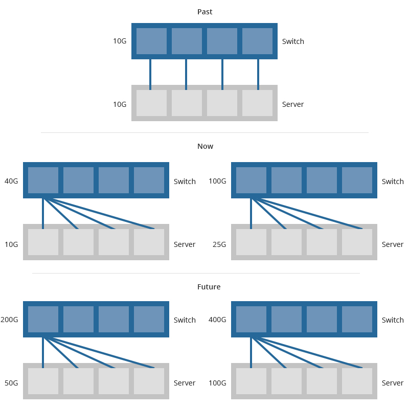
Network switch speed is always driven by server uplink speed. No matter in the past or at present, one-to-four structure is often used to connect switches and servers to increase the port density of switches. And this structure is likely to be adopted in the future as well. Then, how to choose between the 200G Ethernet and 400G Ethernet mainly depends on the server we use.

How to Connect Servers in Data Centers.jpg

According to Crehan research and forecast, the momentum of 100G servers surpassed that of 50G servers since 2020. That means, most network operators are likely to use 100G server connection rather than 50G. And 100G servers would become the mainstream according to the trends during 2020-2023. In other words, one could skip 200G and choose 400G directly with 100G server deployed.

50G vs 100G Server Adoption Rates.jpg

Optical Transceiver Market Drives 400G Ethernet

There are two main factors that push 400G Ethernet more popular than 200G Ethernet in the optical transceiver market. One is the module supply, another is the cost.

400G Optical Transceivers Gain More Market Supplies and Acceptance

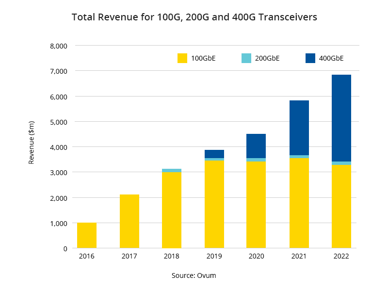
Normally, the early adoption of 400G is to support the rise of 200G long-haul for aggressive DCI network builds. It makes 400G possible in metro networks and supports 3x the distance for 200G wavelengths. WIth further development, 400G transceivers are more favorable among manufacturers. Many suppliers pay more attention to 400G Ethernet rather than 200G. For example, Senko’s new CS connector is specifically designed for 400G data center optimization. Actually, all things have reasons. Even if the total cost of 200G transceiver and 400G transceiver is the same, the cost and power consumption per bit of 400G transceiver is half of the 200G’s because of the doubled bandwidth of 400G. More importantly, the total revenue data among 100G, 200G and 400G shows that 400G is far beyond 200G in the whole market.

Total Revenue for 100G 200G and 400G Transceivers.jpg

According to shipment data of the top 8 suppliers gathered by Omdia, the 400G transceiver market is more prosperous than that of 200G. There are more options for users in 400G deployment. Although the top 8 suppliers all provide 200G and 400G transceivers, 200G transceivers only offer 100m SR4 and 2km FR4 while 400G transceivers could offer more options like SR8 100mDR4 500mFR4 2kmLR4 10km, and ER8 40km, etc. In addition, 400G products, such as 400G DAC and 400G DAC breakout cables and solutions are maturer and more perfect than 200G because of their earlier release.

Supplier SupportFinisarInnolightFITLumentumAccelinkSource PhotonicsAOIHisense
200G SR4      
200G FR4    
400G SR8
400G SR4.2     
400G DR4
400G FR4
400G ZR       

400G Optical Modules Support More Applications With Fewer Cost

Compared to 200G transceivers, 400G transceivers could support more applications including DCI and 200G applications. And they can double the traffic carrying capacity between applications than 100G/200G solutions. With 400G solutions, fewer transponders will be needed, resulting in less transportation and operating costs. This will make the 400G market more lively in return.

400G Ethernet Is more Suitable for Future Network Upgrades

The 200G optical modules will include two main form factors, namely QSFP-DD and CFP2. The 400G optical transceivers will mainly include QSFP-DD and OSFP packages. Since the OSFP is expected to offer a better path to 800G and higher transmission rates, 400G transceiver is more suitable and convenient for future network migration.

Conclusion

From the current analysis and evidence above, 400G Ethernet is more competitive than 200G Ethernet in Ethernet standardization, 100G server connection, optical transceiver market and future network upgrades. There is no need to hesitate between 200G Ethernet and 400G Ethernet. Choosing 400G Ethernet and products is a wise decision not only for the current but for the long-term future.

Article Source

https://community.fs.com/blog/200g-vs-400g-ethernet.html

Related Articles

https://community.fs.com/blog/optical-transceiver-market-200g-400g.html

https://community.fs.com/blog/400g-etherent-market.html

400ZR: Enable 400G for Next-Generation DCI

Share

To cope with large-scale cloud services and other growing data center storage and processing needs, the data center systems have become increasingly decentralized and difficult to manage. And applications like artificial intelligence (AI) urgently need low-latency, high-bandwidth network architectures to support the large number of machine-to-machine input/output (I/O) generated between servers. To ensure the basic performance of these applications, the maximum fiber propagation between these distributed data centers must be limited to about 100 km. Therefore, these data centers must be connected in distributed clusters. In order to ensure high-bandwidth and high-density data center interconnection at the same time, 400G ZR came into being. In this post, we will reveal what 400ZR is, how it works and the influences it brings about.

What Is 400ZR?

400ZR, or 400G ZR, is a standard that will enable the transmission of multiple 400GE payloads over Data Center Interconnect (DCI) links up to 80 km using dense wavelength division multiplexing (DWDM) and higher-order modulation. It aims to ensure an affordable and long-term implementation based on single-carrier 400G using dual-polarization 16 QAM (16-state quadrature amplitude modulation) at approximately 60 gigabaud (Gbaud). Developed by Optical Interconnect Forum (OIF), the 400ZR project is essential to facilitate the reduction of the cost and complexity of high-bandwidth data center interconnects and to promote interoperability among optical module manufacturers.

400G ZR

Figure 1: 400G ZR Transceiver in DCI Switch or Router

How Does 400ZR Work?

400G ZR proposes a technology-driven solution for high-capacity data transmission, which could be matched with the 400GE switch port. It uses a unique design of advanced coherent optical technology for small, pluggable form factor modules. Although the product form factor is not specified in the IA (implementation agreement), the companies or groups contributing to the 400ZR have defined this specification to fit the solution. These form factors defined separately by Multi-Source Agreement (MSA) bodies specify compact mechanical transceivers like QSFP-DD and OSFP, which are connectorized and pluggable into a compatible socket in a system platform. That is to say, the compatible 400ZR solutions that come to market will also be interoperable since the OIF and form factor MSAs are industry-wide organizations. And the interoperability of the 400ZR solutions offers the dual benefit of simplified supply chain management and deployment.

400ZR+ for Longer-reach Optical Transmission

Like other 400G transceivers, the pluggable coherent 400ZR solution can support 400G Ethernet interconnection and multi-vendor interoperability. However, it is not suitable for next-generation metro-regional networks that need transmission over 80 km with a line capacity of 400 Gb/s. Under such circumstances, 400ZR+, or 400G ZR+ is proposed. The 400ZR+ is expected to further enhance modularity by supporting multiple different channel capacities based on coverage requirements and compatibility with installed metro optical infrastructure. With 400ZR+, both the transmission distance and line capacity could be assured.

What Influences Will 400ZR Bring About?

Although 400ZR technology is still in its infancy, once it is rolled out, it will have a significant impact on many industries as the following three: hyper-scale data centers, distributed campuses & metropolitan areas and telecommunications providers.

400ZR Helps Cloud and Hyperscale Data Centers Adapt to the Growing Demand for Higher Bandwidth

The development of DCI and 400ZR could help cloud and hyper-scale data centers adapt to the growing demand for higher bandwidth on the network. They could deal with the exponential growth of applications such as cloud services, IoT devices, and streaming video. As time goes by, 400G ZR will contribute more to the ever-growing applications and users for the whole networking.

400ZR Will Support Interconnects in Distributed Data Centers

As is mentioned above, 400ZR technology will support the necessary high-bandwidth interconnects to connect distributed data centers. With this connection, distributed data centers can communicate with each other, share data, balance workloads, provide backup, and expand data center capacity when needed.

400ZR Allows Telecommunications Companies to Backhaul Residential Traffic

400G ZR standard will allow telecommunications companies to backhaul residential traffic. When running at 200 Gb/s using 64 Gbaud signalings and QPSK modulation, 400ZR can increase the range of high loss spans. For 5G networks, 400G ZR provides mobile backhaul by aggregating multiple 25 Gb/s streams. 400ZR helps promote emerging 5G applications and markets.

400ZR+/400ZR- Will Provide Greater Convenience Based on 400ZR

In addition to the interoperable 400G mode, the 400ZR transceiver is also expected to support other modes to increase the range of addressable applications. These modes are called 400ZR + and 400ZR-. “+” indicates that the power consumption of the module exceeds the 15W required by IA and some pluggable devices, enabling the module to use more powerful signal processing technology to transmit over distances of hundreds of kilometers. “-” indicates that the module supports low-speed modes, such as 300G, 200G, and 100G, which provide network operators with more flexibility.

Will 400ZR Stay Popular In the Next Few Years?

According to the data source below from LightCounting, 400ZR will lead the growth of optical module sales in 2021-2024. The figure below shows the shipment data of high-speed (100G and above) and low-speed (10G and below) DWDM modules sold on the market. It is clear that modules used in Cloud or DCI have an increasing tendency in 2021-2024. That means 400ZR will lead annual growth from 2021.

Source

In addition, with the first 100Gbps SerDes implementation in switching chips expected in 2021, the necessary data rate will move to 800 Gbps within the next 1-2 years for the optics interface. Since the OSFP form factor has been defined to allow an 8x 100GE interface without changing the definition of the transceiver. Similarly, in parallel, the coherent optics on the line side will transition to support 128GBaud 16QAM within a similar time frame, making it easy to migrate from the current 400ZR to the next-generation 800ZR. Therefore, 400ZR is crucial no matter in the current or the future network development.

Article Source

https://community.fs.com/blog/400zr-enable-400g-for-next-generation-dci.html

Related Articles:

https://community.fs.com/blog/400g-qsfp-dd-transceiver-types-overview.html

https://community.fs.com/blog/400g-osfp-transceiver-types-overview.html

Silicon Photonics: Next Revolution for 400G Data Center

Share
400G

With the explosion of 5G applications and cloud services, traditional technologies are facing fundamental limits of power consumption and transmission capacity, which drives the continual development of optical and silicon technology. Silicon photonics is an evolutionary technology enabling major improvements in density, performance and economics that is required to enable 400G data center applications and drives the next-generation optical communication networks. What is silicon photonics? How does it promote the revolution of 400G applications in data centers? Please keep reading the following contents to find out.

What Is Silicon Photonics Technology?

Silicon photonics (SiPh) is a material platform from which photonic integrated circuits (PICs) can be made. It uses silicon as the main fabrication element. PICs consume less power and generate less heat than conventional electronic circuits, offering the promise of energy-efficient bandwidth scaling.

It drives the miniaturization and integration of complex optical subsystems into silicon photonics chips, dramatically improving performance, footprint, and power efficiency.

Conventional Optics vs Silicon Photonics Optics

Here is a Technology Comparison Chart between Conventional Optics vs Silicon Photonics Optics, taking QSFPDD DR4 400G module and QDD DR4 400G Si for example:

The difference between a 400GBASE-DR4 QSFP-DD PAM4 optical transceiver module and a silicon photonic one just lies in: 400G silicon photonic chips — breaking the bottleneck of mega-scale data exchange, showing great advantages in low power consumption, small footprint, relatively low cost, easiness for large volume integration, etc.

Silicon photonic integrated circuits provide an ideal solution to realize the monolithic integration of photonic chips and electronic chips. Adopting silicon photonic design, a QDD-DR4-400G-Si module combines high-density & low-consumption, which largely reduces the cost of optical modules, thereby saving data center construction and operating expenses.

Why Adopt Silicon Photonics in Data Centers?

To Solve I/O Bottlenecks

The world’s growing data demand has caused bandwidths and computing power resources in data centers to be used up. Chips have to become faster when facing the growing demand for data consumption, which can process information faster than the signal can be transmitted in and out. That is to say, chips are becoming faster, but the optical signal (coming from the fiber) must still be converted to an electronic signal to communicate with the chip sitting on a board deep in the data center. And since the electrical signal still needs to travel some distance from the optical transceiver, where it was converted from light, to the processing and routing electronics — we’ve reached a point where the chip can process information faster than the electrical signal can get in and out of it.

To Reduce Power Consumption

Heating and power dissipation are enormous challenges for the computing industry. Power consumption will directly translate to heat. Power consumption causes heat, so what causes power dissipation? Mainly, data transmissions. It’s estimated that data centers have consumed 200TWh each year — more than the national energy consumption of some countries. Thus, some of the world’s largest Data Centers, including those of Amazon, Google, and Microsoft are located in Alaska and similar-climate countries due to the cold weather.

To Save Operation Budget

At present, a typical ultra-large data center has more than 100,000 servers and over 50,000 switches. The connection between them requires more than 1 million optical modules with around US$150 million-US$250 million, which accounts for 60% of the cost of the data center network, exceeding the sum of equipment such as switches, NICs, and cables. The high cost forces the industry to reduce the unit price of optical modules through technological upgrades. The introduction of fiber optic modules adopting Silicon Photonics technology is expected to solve this problem.

Silicon Photonics Applications in Communication

Silicon photonics has proven to be a compelling platform for enabling next-generation coherent optical communications and intra-data center interconnects. This technology can support a wide range of applications, from short-reach interconnects to long-haul communications, making a great contribution to next-generation networks.

  • 100G/400G Datacom: data centers and campus applications (to 10km)
  • Telecom: metro and long-haul applications (to 100 and 400 km)
  • Ultra short-reach optical interconnects and switches within routers, computers, HPC
  • Functional passive optical elements including AWGs, optical filters, couplers, and splitters
  • 400G transceiver products including embedded 400G optical modules400G DAC Breakout cables, transmitters/receivers, active optical cables (AOCs), as well as 400G DACs.

Now & Future of Silicon Photonics

Yole predicted that the silicon optical module market would grow from approximately US$455 million in 2018 to around US$4 billion in 2024 at a CAGR of 44.5%. According to Lightcounting, the overall data communication high-speed optical module market will reach US$6.5 billion by 2024, and silicon optical modules will account for 60% (3.3% in 20 years).

Intel, as one of the leading Silicon photonics companies, has a 60% market share in silicon photonic transceivers for datacom. Indeed, Intel has already shipped more than 3 million units of its 100G pluggable transceivers in just a few short years, and is continuing to expand its Silicon Photonics’ product offerings. And Cisco acquired Accacia for US$2.6 billion and Luxtera for US$660 million. Other companies like Inphi and NeoPhotonics are proposing silicon photonic transceivers with strong technologies.

Original Source: Silicon Photonics: Next Revolution for 400G Data Center

400G QSFP Transceiver Types and Fiber Connections

Share

400G QSFP has become one of the most popular form factors in the next-generation network. And different types of modules have appeared in the 400G optical transceiver market. What are 400G QSFP-DD transceiver types? What fiber cables could be used with these 400G optical modules? What about the answers to frequently asked questions about 400G QSFP? This post will illustrate them thoroughly.

400G QSFP Transceiver Types

400G QSFP transceivers are introduced respectively in the following table according to the two transmission types (over multimode fiber and single-mode fiber) they support.

Transmission TypeQSFP-DD Product DescriptionReachOptical ConnectorWavelengthOptical ModulationProtocol
Multimode fiber400G QSFP-DD SR8up to 100m over OM4 or OM5
up to 70m over OM3
MTP-16/MPO-16850nm50G PAM4IEEE P802.3cIEEE 802.3cd
Single-mode fiber400G QSFP-DD DR4up to 500m over parallel SMFMTP-12/MPO-121310nm100G PAM4IEEE 802.3bs
400G QSFP-DD XDR4/DR4+up to 2km over parallel SMFMTP-12/MPO-121310nm100G PAM4/
400G QSFP-DD FR4up to 2km over duplex SMFLCCWDM4 wavelength100G PAM4100Glambda MSA
400G QSFP-DD 2FR4up to 2km over duplex SMFCSCWDM4 wavelength50G PAM4IEEE 802.3bs
400G QSFP-DD LR4up to 10km over duplex SMFLCCWDM4 wavelength100G PAM4100Glambda MSA
400G QSFP-DD LR8up to 10km over duplex SMFLCCWDM4 wavelength50G PAM4IEEE 802.3bs
400G QSFP-DD ER8up to 40km over duplex SMFLC1310nm50G PAM4IEEE 802.3cn

Fiber Connections for 400G QSFP Transceivers

QSFP 400G SR8

  • A QSFP-DD SR8 can interop with another QSFP-DD SR8 over an MTP-16/MPO-16 cable. This is the most popular connection using an MTP-16/MPO-16 cable to connect two QSFP-DD SR8 transceivers directly.
  • 400G QSFP-DD SR8 breaks out to 2× 200G SR4.
  • QSFP-DD SR8 interops with 8× 50G SR over MPO-16 to 8× LC duplex fiber cables.

QSFP 400G DR4

  • QSFP-DD DR4 interops with QSFP-DD DR4 over an MPO-12 trunk cable.
    • 400G QSFP-DD DR4 interops with 4× 100G DR over MPO-12 to 4× LC duplex breakout cable.
    QSFP-DD DR4 to 4x 100G Breakout Connection

    QSFP 400G XDR4/DR4+

    • QSFP-DD XDR4/DR4+ interops with QSFP-DD XDR4/DR4+ over an MPO-12 trunk cable.
      • 400G QSFP-DD XDR4 interops with 4× 100G FR modules over an MPO-12 to 4× Duplex LC cable.

      QSFP 400G FR4

      QSFP-DD FR4 interops with QSFP-DD FR4 over a duplex LC cable.

      QSFP-DD FR4 Connection

      QSFP 400G 2FR4

      QSFP-DD 2FR4 interops with 2× 200G FR4 over 2× CS to 2× LC duplex cable.

      QSFP-DD 2FR4 Connection

      QSFP 400G LR4

      QSFP-DD LR4 interops with QSFP-DD LR4 over an LC duplex cable.

      QSFP-DD LR4 Connection

      QSFP 400G LR8

      QSFP-DD LR8 interops with QSFP-DD LR8 over an LC duplex cable.

      QSFP-DD LR8 Connection

      QSFP 400G ER8

      QSFP-DD ER8 interops with QSFP-DD ER8 over an LC duplex cable.

      QSFP-DD ER8 Connection

      400G QSFP Transceivers: Q&A

      Q: What does “SR8”, “DR4”, “XDR4”, “FR4”, “LR4”, and “LR8” mean in QSFP 400G modules?

      A: “SR” refers to short-range, and “8” implies there are 8 optical channels. “DR” refers to 500m reach using single-mode fiber, and “4” implies there are 4 optical channels. “XDR4” is short for “eXtended reach DR4”. And “LR” refers to 10km reach using single-mode fiber.

      Q: Can I plug a QSFP-DD transceiver module into an OSFP port?

      A: No. QSFP-DD and OSFP are totally different form factors. For more information about OSFP transceivers, you can refer to the 400G OSFP Transceiver Types Overview. You can use only one kind of form factor in the corresponding system. Eg, if you have a QSFP 400G system, QSFP-DD transceivers and cables must be used.

      Q: Can I plug a 100G QSFP28 module into a 400G QSFP port?

      A: Yes. A QSFP28 module can be inserted into a QSFP-DD port (without a mechanical adapter). When using a QSFP28 module in a QSFP-DD port, the QSFP-DD port must be configured for a data rate of 100G instead of 400G.

      Q: What other breakout options are possible apart from using the 400G QSFP-DD modules mentioned above?

      A: 400G QSFP-DD DACs & AOCs are possible for breakout 400G connections. See 400G Direct Attach Cables (DAC & AOC) Overview for more information about 400G DACs & AOCs.

      Article Source

      https://community.fs.com/blog/400g-qsfp-dd-transceiver-types-overview.html

      Related Articles

      https://community.fs.com/news/400g-qsfp-dd-solution-for-400g-data-center-interconnect.html

      https://community.fs.com/blog/400g-ethernet-400g-transceiver.html