Definition of armored fiber optic cable
Armored Fiber Optic Cable, just as the name implies, is that there is a layer of additional protective metal armoring of the fiber optic cable.
 Function
Armored fiber cable plays a very important role in long-distance line of fiber optic cable. A layer of metal armoring in the scarf-skin of fiber optic cable protects the fiber core from rodent, moist and erosion.
Classification
According to the place of use, there are indoor armored fiber optic cables and outdoor armored fiber optic cables.
Indoor armored fiber optic cable
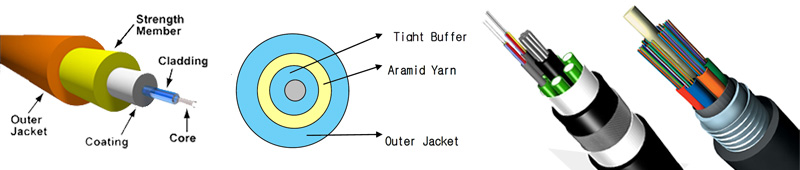
Indoor armored fiber optic cable is mainly used in interior, so it must be flexible and can be installed in the corner and some narrow places. Besides, indoor armored fiber optic cable experiences less temperature and mechanical stress, but they have to be fire retardant, emit a low level of smoke in case of burning. And indoor armored fiber cables must allow a small bend radius to make them be amendable to vertical installation and handle easily.
Indoor armored fiber optic cable can be divided into simplex armored fiber optic cable and duplex armored fiber optic cable. The main difference is that simplex armored fiber optic cable is the cable that not contains stainless steel wire woven layer, and duplex armored fiber optic cable is the cable that contains stainless steel hose and stainless steel wire woven which are of compressive property, resistance to deflection, rodent resistance, anti-torque and so on.
Outdoor armored fiber optic cable
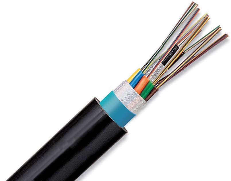
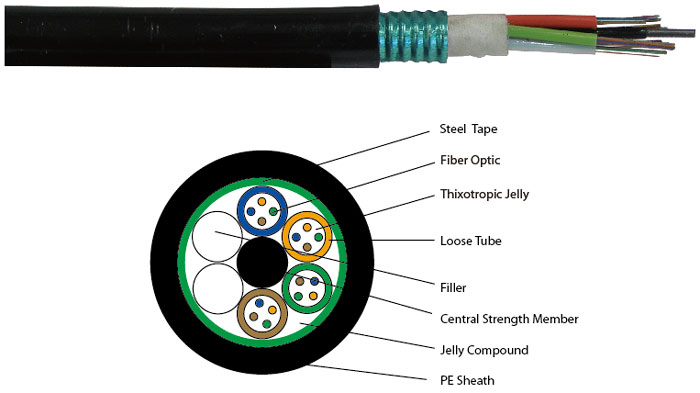
Outdoor armored fiber optic cables are made to protect the optical fiber to operate safely in complicated outdoor environment. Most armored outdoor fiber cables are loose buffer design, with the strengthen member in the middle of the whole cable, the loose tubes surround the central strength member.
Outdoor armored fiber optic cable can be divided into light armored fiber optic cable and heavy armored fiber optic cable. Light armored fiber optic cable is with steel tape and aluminium tape which can strengthen rodent protection. Heavy armored fiber optic cable is equipped with a circle of steel wire, and usually used in riverbed and seabed.
Installation
There are two installation methods of armored fiber optic cable. One is buried directly in the ground, and the other is aerial optical cable.
For direct burial fiber cable, armored fiber optic cable is in the position to resist external mechanical damage, prevent erosion and resist rodent. In addition, because of different soil and environment, the depth of burying under the ground is about between 0.8m-1.2m.
On the other hand, aerial optical cable is the optical cable that hanging on the pole. This kind of installation way of armored fiber optic cable can prevent fiber core from any kind of severe environment, such as typhoon, ice, and people or animals. Aerial armored optical cable mostly uses central loose tube armored fiber optic cable (GYXTW) and stranded loose tube armored fiber optic cable (GYTA). The features of GYXTW are that can contain up to 12 fiber cores, the loose tube is centrally situated with good excess length and minimizes the influence of lateral crush, and double wire as strength member provides excellent strain performance. GYTA is suitable for installation for long haul communication and LANs, especially suitable for the situation of high requirements of moisture resistance. GYTA is with compact structure; the cable jacket is made of strong Polyethylene. This armored fiber optic cable features the good mechanical and temperature performance. GYTA is also with high strength loose tube that is hydrolysis resistant and the optical cable filling materials ensure high reliability, its APL makes the cable crush resistant and moisture proof. The GYTA fiber optic cable is available from 2 cores to 144 cores.
 An Optical Power Meter usually knows as Fiber optical power meter is a device that used to measure the absolute optical signal and relate fiber optic loss. The term usually refers to a device for testing average power in fiber optic systems. Fiber optical power meter is a tool for telecommunication and CATV network.
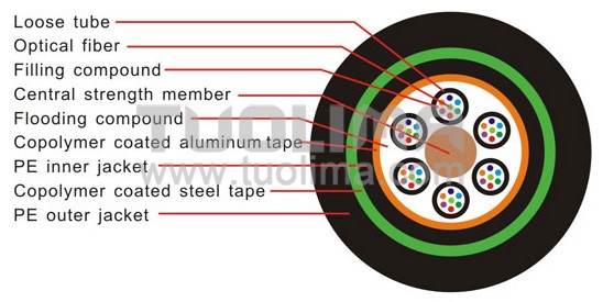


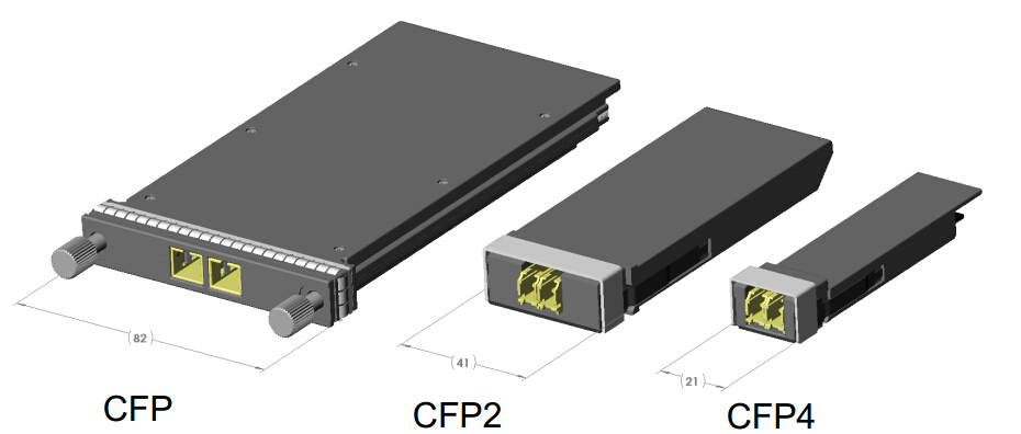
 CXP is targeted at the clustering and high-speed computing markets, so we usually called it high-density CXP. Technically, the CFP will work with multimode fiber for short-reach applications, but it is not really optimized in size for the multimode fiber market, most notably because the multimode fiber market requires high faceplate density. The CXP was created to satisfy the high-density requirements of the data center, targeting parallel interconnections for 12x QDR InfiniBand (120 Gbps), 100 GbE, and proprietary links between systems collocated in the same facility. The InfiniBand Trade Association is currently standardizing the CXP.


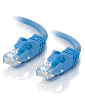 Cat6 Cables
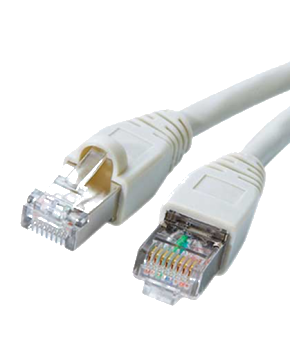 Cat6a Cables